GMDE GHESS 5.0_6.0KWH User guide
–GHESS 5.0_6.0KWH
GMDE 3-Phase Solar Battery Hybrid Storage System
Installation and Application Guide
Version 1.0

CONTENT
1. Unpacking and Packaging list ........................................................................................................3
2. System Overview...........................................................................................................................3
System Overview Diagram ................................................................................................3
System Specification..........................................................................................................4
2.1 Main System Components ..................................................................................................5
2.2 Internal Topology Illustration ..............................................................................................6
2.3 Output Connectors Illustration ...........................................................................................7
3. Installation.....................................................................................................................................7
3.1 Install the inverter ...............................................................................................................7
3.2 Install the battery packs ......................................................................................................8
3.3 External Line Connection ..................................................................................................11
4. System Operation........................................................................................................................13
4.1 System Start-Up.................................................................................................................13
4.2 System Interface................................................................................................................13
4.2.1 Main Operation Modes ..........................................................................................13
4.2.2 Operation Interface................................................................................................14
4.2.2 Change Operation Modes ......................................................................................15
4.3 System Turn-off .................................................................................................................17
5. Trouble Shooting .........................................................................................................................18
5.1 Fault Messages and Action List .........................................................................................18
5.2 Fault Acknowledgement....................................................................................................20
5.3 Technical Service ...............................................................................................................20
1. Unpacking and Packaging list
Before installation, please unpack the system packages and check if all the system components
are available according to list below. Or should any components listed below are damaged during
transport, please contact your seller or the supplier GMDE.
Packaging List
System Component
1.
Hybrid Inverter Powervortex 305KTL
1 PCS
2
GMDE 19”System Cabinet (with EMS unit, On/Off-grid switching box,
Battery Control Box 150V integrated, energy meter included )
1 PCS
3
Battery Module M15020
2 PCS
Document
4
User Manual
1 PCS
Table 1 Packaging List
2. System Overview
This manual describes the installation and operation of the GHESS series solar battery hybrid
energy storage system (HESS). The GHESS series hybrid energy storage system is designed and
developed by GMDE Technology Ltd. and can be widely used in residential applications. In which,
the GHESS 5.0_6.0kWh refers to a solar battery hybrid system with 5.0kW nominal AC output
power and 6.0kWh lithium-ion battery capacity. As the battery module adopted in this system is
150V20Ah cell, this system is battery capacity extendable with each step 3kWh (150V20Ah).
System Overview Diagram
Figure 1 is an overview diagram when installing the GHESS system and connecting it with Grid
and Load.

Figure 1 System Overview Diagram
System Specification
Table 2 is the brief spec of the GHESS 5.0_6.0kWh solar battery hybrid energy storage system.
MODEL
GHESS 5.0_6.0kWh
System parameters
Nominal/useable capacity[kWh]
6.0/4.80@80%DoD
Installation
All-in-one cabinet
Warranty [year]
5 years standard, battery 10 years extendable
PV side input
Max. input power [kW]
5.0
MPPT voltage range[V]
280-800
MPPT tracker
1
Battery side input
Operating voltage range[V]
150@[120, 500]
Max. charging power[kW]
4.0
Max. charging current [A]
18
Charging/discharging efficiency
96.5%/96.5%
AC output-on grid
Max. output power[kW]
5.0
Output voltage range[V]
3N~400, 324-436, 437-460(<10min.)
Certification
VDE-AR-N4105, IEC62109
AC output-off grid (Optional)
Rated voltage & frequency [V/Hz]
400±2%,50±2%
Output power [kW]
Rated power 2.5, instantaneous power 5.0
Power factor
[-0.7, +0.7]
Battery packs
The lithium iron phosphate battery pack
Nominal capacity [kWh]
6.0
Public Grid
M
Utility Meter
(Existed)
Meter
Load
Emergency
Load
PVMeter
AC GRID AC LOAD
Module/unit
150V/20Ah lithium-ion module*2 modules in parallel
Life cycle
80% DOD for 3000 life cycles
Visual interface
EMS
EMS
7 inch color touch screen
Interface communication
RS485/RS232/USB/Ethernet/Wifi
Table 2 GHESS 5.0_6.0kWh system specification
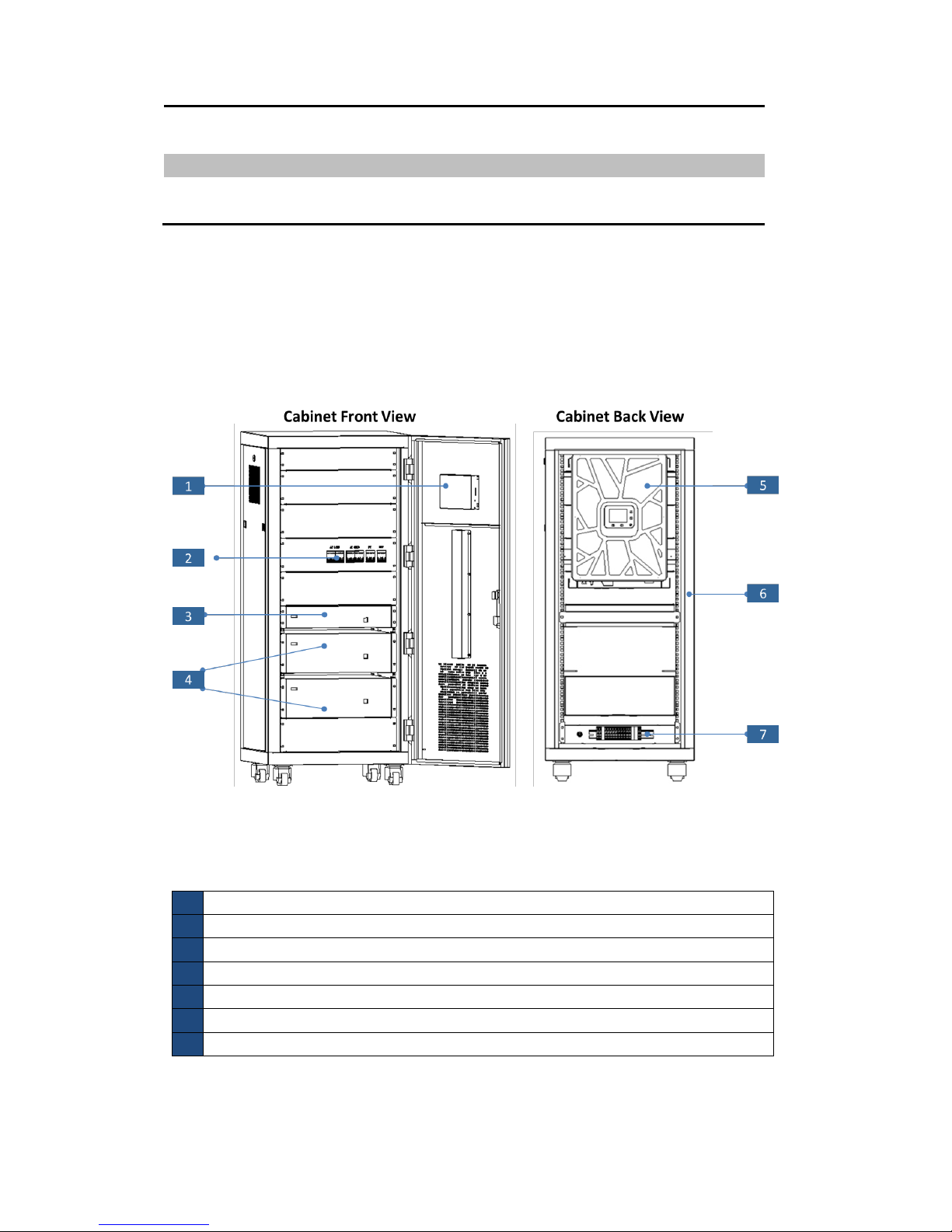
2.1 Main System Components
Viewing from outside, you’ll see the system is consisted of the main parts below:
Figure 2 Main System Components
Illustration:
1
Energy Management System(EMS) unit
2
System Circuit Breakers(AC GRID/ Emergency Load/PV/BAT)
3
Battery Control Box 150V
4
Battery Modules 150V20Ah
5
Hybrid Inverter 5kW
6
System Cabinet
7
Output Connectors
Table 3 System components list
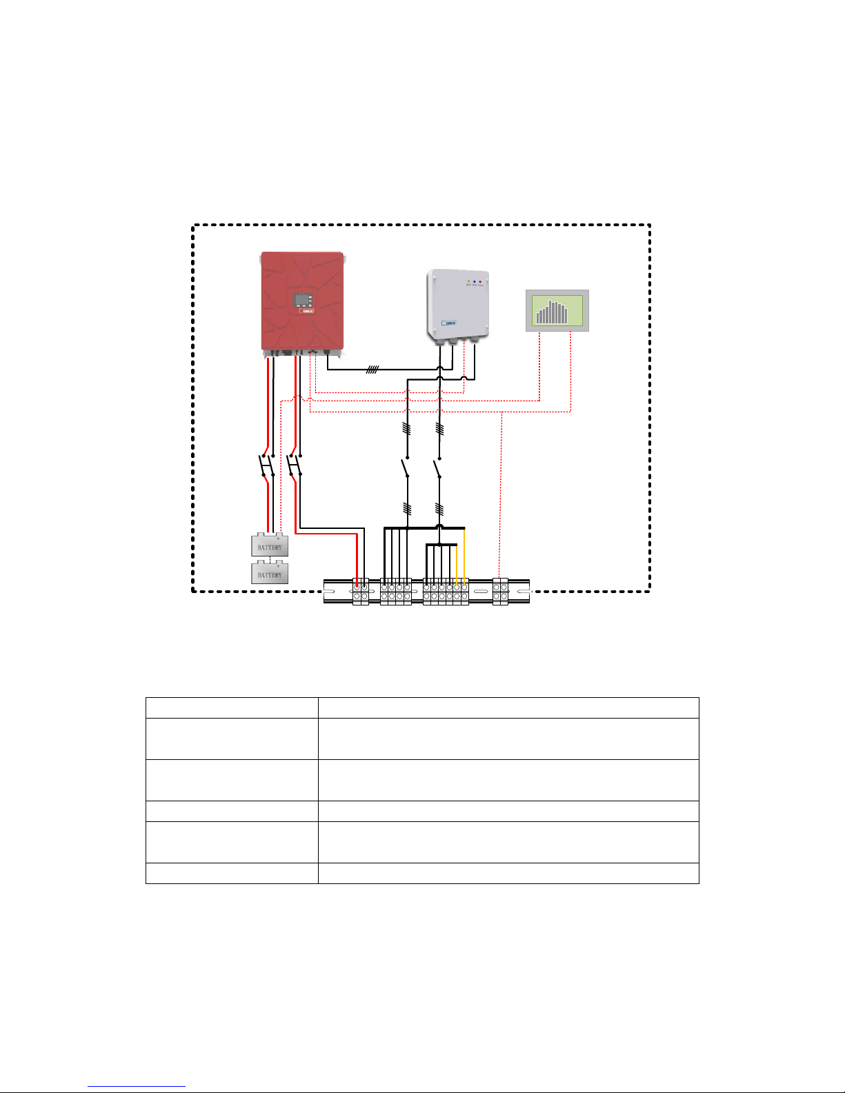
2.2 Internal Topology Illustration
Figure 3 is the internal electrical topology of the system. The main functional components
contained in this system are:
Figure 3 Internal system topology
Component
Function
Hybrid inverter
To transfer the DC current generated by PV panel into AC current
and to charge/discharge the battery packs
On/off-grid Auto-switching
box
To switch the system from grid-tied to off-grid operation mode
when grid failure happens
Energy Management System
To monitor and control the system operation
Battery packs (including
Battery Control Box)
To store the energy generated by PV panels or from the public
grid
Energy meter
AC data collection and transportation
Table 4 Main function components
PowerVortex 305
Hybrid Inverter
GMDE On/Off Grid Auto-
Switching Box
Energy Management
System
BAT+
BAT- PV+
PV-
RS485CAN
COM
RS485
PV Meter
AC GRID AC LOAD
+ - L1 L2 L3 N L1 L2 L3 N PE PE
PIN8
PIN7
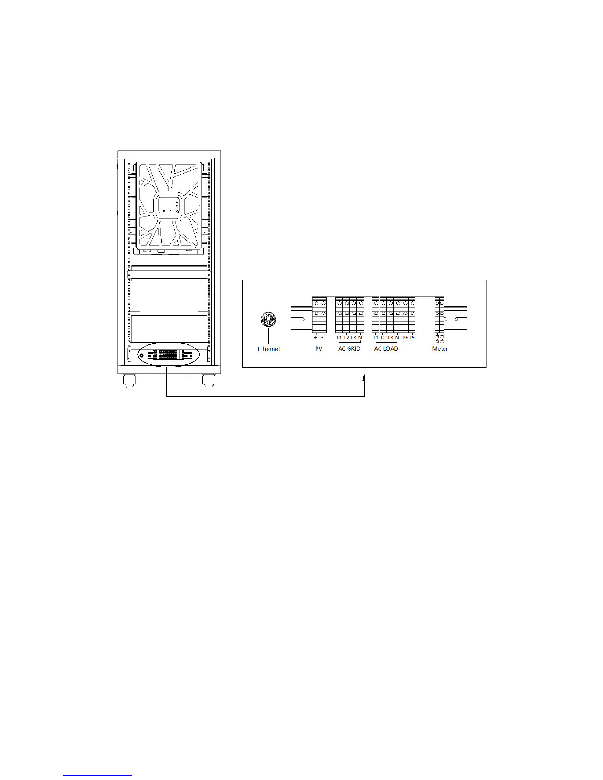
2.3 Output Connectors Illustration
Viewing from the back side of the cabinet, at the bottom of the cabinet, you can find the output
connectors, as shown in Figure 4.
Figure 4 Output connectors
3. Installation
The system is very easy to install. Insert the battery modules and hybrid inverter into the system
cabinet according to the following steps in Section 3.2 Install the battery packs and Section 3.1
Install the inverter; finish the output line connection according to Section 3.3 External Line
Connection; check and then the system installation is done.
3.1 Install the inverter
Please follow these steps to install the inverter into the system cabinet:
1) Align with wall bracket, move Powervortex 305KTL hybrid inverter in horizontal direction to
proper position;
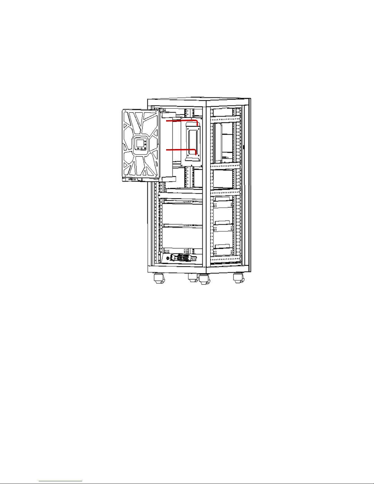
2) Make the hook on wall bracket insert into the hole on the back of Powervortex 305KTL hybrid
inverter;
3) Slowly lower the hybrid inverter , ensure the device hang on the hook of wall bracket;
4) Check if the hybrid inverter is properly fixed on the wall.
Figure 5 Inverter installation
3.2 Install the battery packs
5) Insert the battery modules into the system cabinet, as shown in Figure 6;
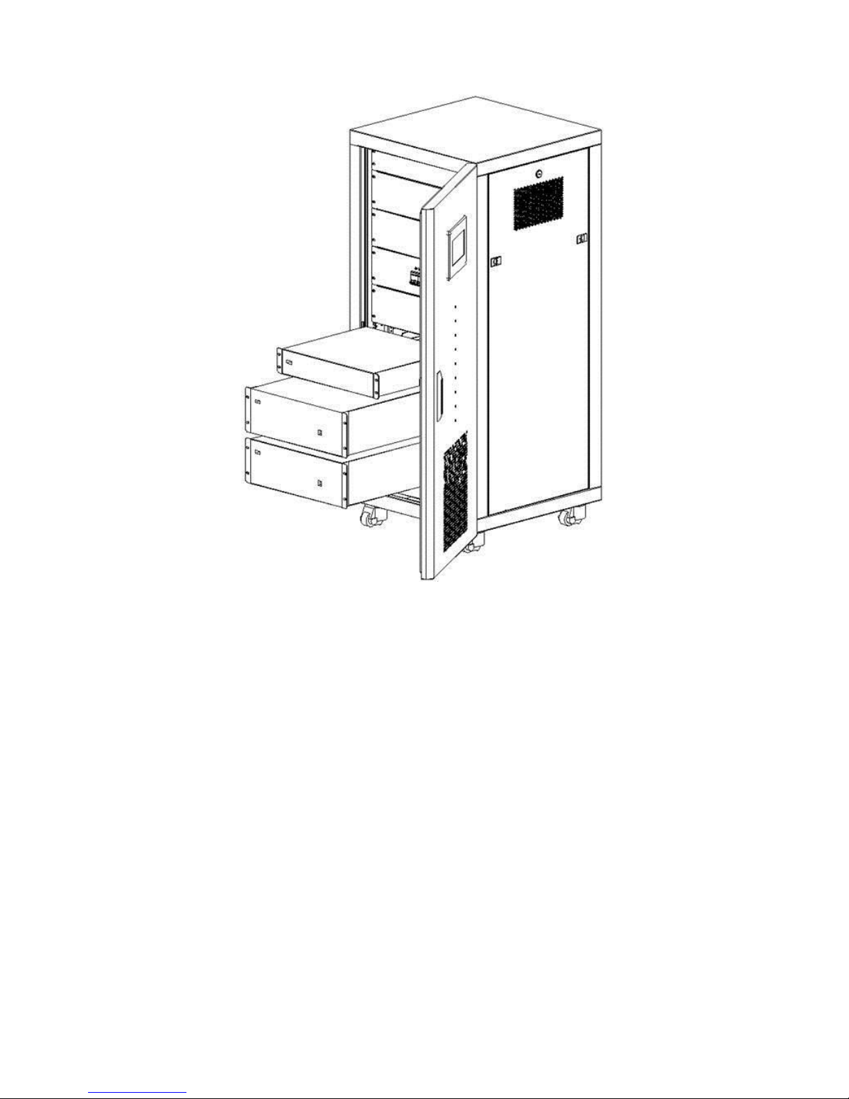
Figure 6 Battery installation
2) At the back side of the cabinet, connect the hybrid inverter, Battery Control Box and battery
modules with the lines as shown in Figure 7; the detailed DC line connection between inverter
and battery packs are illustrated in Figure 8. (The battery packs are connected in parallel, which
means the final battery pack equals to 150V/40Ah)
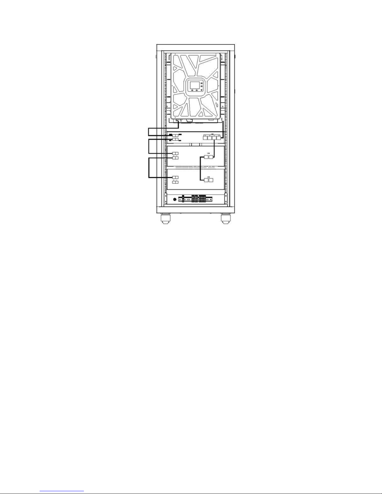
Figure 7 Battery line connection
Table of contents
Other GMDE Inverter manuals


