Darfon MIG300 User manual

INSTALLATION MANUAL
MIG300 MICRO INVERTER

2| Page ©2014 Darfon America Corp. Rev. 04
INSTALLATION MANUAL MIG300 MICRO INVERTER
TABLE OF CONTENTS
IMPORTANT SAFETY INSTRUCTIONS............................................3
Safety Instructions ............................................................3
Lightning Surge Suppression ..................................................4
FCC Compliance .............................................................4
PRE-INSTALLATION ...........................................................5
Parts and Tools.............................................................. 5
Compatibility and Capacity ................................................... 6
AC Trunk Cable ............................................................. 6
Grounding Options ...........................................................7
INSTALLING THE MICRO INVERTER .............................................8
Installing onto a PV Racking System ........................................... 8
POST-INSTALLATION ..........................................................11
Commissioning and Operating ................................................11
GFDI Fault ..................................................................11
Disconnecting a Micro Inverter ................................................11
MONITORING SYSTEM.........................................................13
PLC Box Overview ...........................................................13
Data Logger Overview .......................................................14
Installing the PLC Box and Data Logger ........................................15
Registering the PV System....................................................16
TROUBLESHOOTING .........................................................20
Troubleshooting the Micro Inverter ...........................................20
Troubleshooting the PLC Box .................................................21
Troubleshooting the Data Logger..............................................21
TECHNICAL SPECIFICATIONS .................................................22
MIG300 Micro Inverter ......................................................22
PLC Box ................................................................... 23
Data Logger ............................................................... 23
SAMPLE WIRING DIAGRAM....................................................24
INSTALLATION MAP TEMPLATE................................................25
NOTES......................................................................26

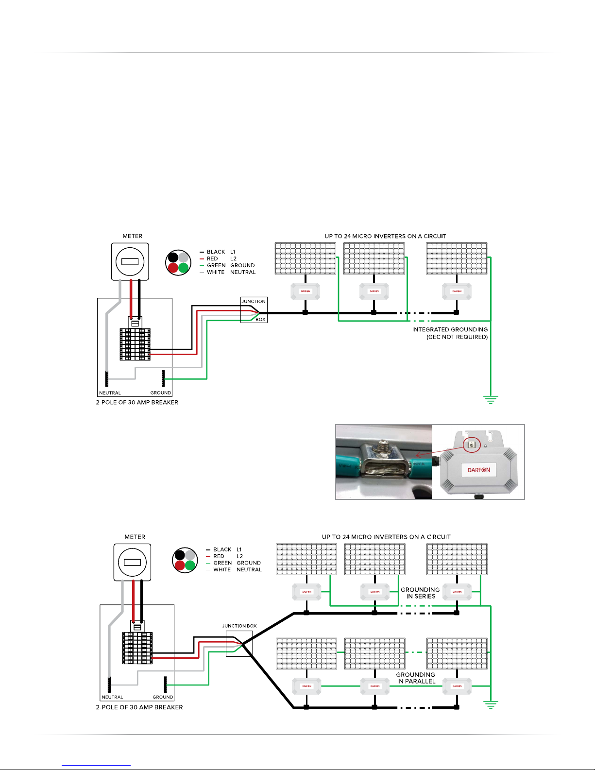
Rev. 04 ©2014 Darfon America Corp. 3| Page
MIG300 MICRO INVERTER INSTALLATION MANUAL
IMPORTANT SAFETY INSTRUCTIONS
PLEASE READ THESE INSTRUCTIONS BEFORE INSTALLING ANY DARFON PRODUCTS OR DEVICES &
KEEP FOR FUTURE REFERENCE.
This manual contains important instructions for the installation and maintenance of Darfon MIG300 micro
inverters. Before installing, please read these safety instructions carefully. Take special care to follow the
warnings indicated on the unit itself as well as the safety instructions listed below.
Safety Symbols
To reduce the risk of injury and to ensure the continued safe operation of this product, the following safety
instructions and warnings are marked in this manual.
WARNING
This indicates the risk of electric shock. The presence of high voltage
levels may constitute a risk of injury or death to users and/or installers.
CAUTION
This indicates important information where failure to comply may
result in safety hazards or cause damage to this product.
Safety Instructions
• Read all instructions and cautionary marks in the manual carefully before starting the installation.
• Do not attempt to repair this product; it does not contain user-serviceable parts. Repairs and internal
servicing should only be performed by Darfon authorized service personnel.
• Do not tamper with or open this product. Opening this product may result in electric shock.
• Perform all electrical installations in accordance with all applicable local electrical codes and the
National Electrical Code (NEC), ANSI/NFPA 70.
• Only qualified electrical personnel should perform the electrical installation and wiring of this product.
• Be aware that even without an external voltage source connected, the MIG300 micro inverter may
contain high voltages and there is a risk of electrical shock.
• Connect the Darfon micro inverter to the utility grid only after receiving prior approval from the
electrical utility company.
• The temperature of the heat sinks outside of the device can reach over 85°C in normal operation. To
reduce risk of burns, use caution when working with micro inverters.
• Do not disconnect the DC power source from the Darfon micro inverter without first disconnecting the
AC power source. Both AC and DC power sources must be disconnected before servicing. Be aware
that DC power/voltage is generated when the photovoltaic array is exposed to light.
• Switch o the circuit breakers before installation and wirings.
• For the safety of installation, remove all conductive jewelry or equipment during the installation or
service of the device parts, connector and/or wiring.
• Do not stand on a wet location while doing installation and wirings. Enclose the outer covering well
before switch on the circuit breakers.
• MIG300 inverters should be installed as instructed in this manual. Failure to comply with these
precautions or with specific warnings elsewhere in this manual violates safety standards of design,
manufacture, and intended use of the device. The manufacturer assumes no liability for the customer’s
failure to comply with these requirements.
• When a GFDI fault (Ground fault) occurs, the LED will flash alternating between orange and red. Please
refer to page 15 for more introductions.

4| Page ©2014 Darfon America Corp. Rev. 04
INSTALLATION MANUAL MIG300 MICRO INVERTER
Lightning Surge Suppression
Lightning does not actually need to strike the equipment or building where the PV system is installed to
cause damage. Often, a strike nearby will induce voltage spikes in the electrical grid that can damage
equipment. Darfon’s micro inverters have integral surge protection; however, if the surge has sucient
energy, the built-in protection in the device would be exceeded and the device could potentially be
damaged. It is recommended to install surge protection as part of any solar installation. We recommend the
following protection devices, which have been tested to ensure that they do not interfere with power line
communications.
Residential: Vendor: Citel, Part Number DS72RS-120 or DS73RS-120
Application: DS72RS-120 is applied when N-G is bound together, or DS73RS-120
were N-G is unbound.
Commercial: Vendor: Citel, Part Number SP-120
Application: Branch panel protection
See the vendor datasheet for DS70R (includes the DS72RS-120) or SP-120 at
http://www.citelprotection.com/english/citel_data_sheets/ac_protection/
FCC Compliance
This equipment has been tested and found to comply with the limits for a Class B digital device, pursuant
to part 15 of the FCC Rules. These limits are designed to provide reasonable protection against harmful
interference in a residential installation. This equipment generates, uses and can radiate radio frequency
energy and, if not installed and used in accordance with the instructions, may cause harmful interference
to radio communications. However, there is no guarantee that interference will not occur in a particular
installation. If this equipment does cause harmful interference to radio or television reception, which can be
determined by turning the equipment o and on, you are encouraged to try to correct the interference by
one or more of the following measures:
• Reorient or relocate the receiving antenna.
• Increase the separation between the equipment and the receiver.
• Connect the equipment into an outlet on a circuit dierent from that to which the receiver is
connected.
• Consult the dealer or an experienced radio/TV technician for help.
Changes or modifications not expressly approved by the party responsible for compliance may void the
user’s authority to operate the equipment.
Other Information
Product information is subject to change without notice. All trademarks are recognized as the property of
their respective owners.

Rev. 04 ©2014 Darfon America Corp. 5| Page
MIG300 MICRO INVERTER INSTALLATION MANUAL
PRE-INSTALLATION
Thank you for choosing Darfon’s MIG300 micro inverter as a key component to your solar power system.
Review and follow the instructions in this section before installing Darfon MIG300 micro inverters.
PV System Layout
The optimal PV array layout will need to be planned before installation. The layout/plan will aect the
wiring and cabling schemes and will need to be adjusted accordingly. The layout will also need to account
for the constraints of the distance between each PV module due to the connectors on the trunk cable and
the distance between the micro inverters and PLC box.
• The maximum cable distance from the PLC box to the farthest MIG300 is 50m (164’).
• It is ideal to tap power from the center of the circuit. So 2 segments of 12 modules for each circuit.
This maximizes the communication signal strength to the PLC box.
• The use of a RS485 specific cable is recommended, such as Belden 3105A; however, any twisted pair
cable can be used, such as CAT5, with some degradation of signal and distance.
Parts and Tools
This section provides a list of equipment and tools needed for installing and setting up the PV system.
Equipment for Micro Inverter Installation
- Sealing caps (for unused T-branch connectors)
- AC trunk cable (with T-branch connectors)
- AC connector removal tool
- End Caps (used at the end of each AC branch circuit)
Equipment for Monitoring System Installation
- Data Logger (Includes AC Adapter, RS485 Connector, Wall-Mounted Frame and Ethernet Cable)
- PLC Box (Includes RS485 Connector)
- Red/Black Wiring for RS485
Other Tools/Equipment
- Outdoor-rated AC junction box(es)
- Cable clips and/or tie wraps
- Gland/strain relief fittings (on per AC junction box)
- Torque wrench & sockets for mounting hardware
- Adjustable/open-ended wrench (for end caps)

6| Page ©2014 Darfon America Corp. Rev. 04
INSTALLATION MANUAL MIG300 MICRO INVERTER
Compatibility and Capacity
Darfon MIG300 micro inverters are electrically compatible with PV modules that have a voltage range of
24V to 40V and a maximum wattage of 300W. Please refer to the ‘Compatible PV Module Calculator’ on
Darfon website at www.darfonsolar.com to verify the PV module is electrically compatible.
Before ordering the PV module, make sure the connector type is compatible with the micro inverter.
Electrical Compatibility
Model PV MPPT Voltage Range PV Module Connector Type
MIG300 24V to 40V MC-4 Locking [Male-Anode (+), Female-Cathode (-)]
-
+
MALE (ANODE)
FEMALE (CATHODE) MALE (CATHODE)
FEMALE (ANODE)
-
+
MALE (CATHODE)
FEMALE (ANODE)
MALE (CATHODE)
FEMALE (ANODE)
Voltage and Capacity
Maximum Number of MIG300s per AC Branch Circuit Overcurrent Protection
240V with 10AWG AC Trunk Cable 24 30Amp Breaker
240V with 12AWG AC Trunk Cable 16 20Amp Breaker
WARNING
DO NOT exceed the maximum number of micro inverters in an AC branch
circuit as listed above.
CAUTION
Each AC branch circuit must be protected by a dedicated circuit breaker of 30A
or less if using 10 AWG trunk cable, or 20A or less if using 12 AWG trunk cable.
AC Trunk Cable
There are dierent types and options for AC
trunk cables. Depending on the orientation of the
installation, the AC trunk cable can be in portrait
or landscape format. Trunk cables can also consist
of three pins (three wires) or four pins (four wires).
Darfon uses the four-pin AC trunk cable.
Pin Wire Color Wire Usage
1 Black L1
2Red L2
3 Green Ground
4 White Neutral

Rev. 04 ©2014 Darfon America Corp. 7| Page
MIG300 MICRO INVERTER INSTALLATION MANUAL
Grounding Options
Option 1: Integrated Grounding
Integrated grounding eliminates the need to install Grounding Electrode Conductor (GEC) to each MIG300
by completely isolating the internal DC circuit from the AC circuit and ground. DC ground faults are
detected on either the positive and/or negative conductors of the DC circuit by a Ground Fault Detection
Interrupter Insulation Monitor (GFDI IM). If the GFDI IM detects a ground fault has occurred to the PV
input, the micro inverter will automatically disconnect all conductors and cease supplying output power. In
accordance with NEC 690.35. Installers can build ungrounded arrays where only an Equipment Grounding
Conductor (EGC) is required to connect or bond non-current carrying metal equipment together. The EGC
grounding process is completed via the grounding connection of MIG300 4-wire AC cable to the AC trunk
cable. The PV module will still need to be grounded according to the module manufacturer’s instructions.
Option 2: GEC Grounding
Although the MIG300 oers integrated grounding (UL
1741 certified), it also comes with a grounding terminal
clip for any localities that do not accept integrated
grounding. Darfon will not be held responsible for
improper installations that do not have local AHJ and/or
Utility operational approval.
As indicated in the diagram below, the array GEC can be installed either in series or in parallel.

8| Page ©2014 Darfon America Corp. Rev. 04
INSTALLATION MANUAL MIG300 MICRO INVERTER
INSTALLING THE MICRO INVERTER
The following sections list steps on how to install the Darfon MIG300 micro inverter onto standard PV
racking.
Installing onto a PV Racking System
Step 1: Measure the AC Service at the Site
Measure service entrance conductors to confirm AC service
at the site. Verify that the AC voltages at the electrical utility
connection and at the junction box for each AC branch
circuit are within the ranges.
Step 2: Install the AC Branch Circuit Junction Box
2.1 Mount the adapter plate to a suitable location on the PV racking
system (typically at the end of a row of modules). The adapter
plate must be installed with an appropriate junction box.
2.2 Connect the open wire end of the AC interconnect cable into the
junction box using an appropriate gland or strain relief fitting. The AC
interconnect cable requires a strain relief connector with an opening
of 3/8 inches in diameter.
Step 3: Lay Out the AC Trunk Cable
Place the AC trunk cable at the required location. Align the T-branch connector to the position
where the micro inverter will be installed. Then secure the cable on either side of the rack using
cable clips or tie wraps.
Step 4: Attach the Micro Inverter to the PV Racking
4.1 Note the approximate centers of each PV
module on the PV racking.
4.2 Evaluate the location of the micro inverter
against potential collection of moisture or water.
4.3 Evaluate the location of the micro inverter with
respect to the DC junction box and the PV
module frame.
4.4 Align the MIG300 so that the holes on the
mounting bracket are above the slot opening on
the PV racking and secure the micro inverter to
the PV racking with screws.
CAUTION
Ensure that the inverter does not obstruct the PV module frame or stien braces.
Ensure the micro inverter’s AC connector can easily reach the T-branch connector.
240 Volt AC Single Phase
L1 to L2 211 to 264 VAC
L1, L2 to neutral 106 to 132 VAC

Rev. 04 ©2014 Darfon America Corp. 9| Page
MIG300 MICRO INVERTER INSTALLATION MANUAL
Step 5: Ground the Micro Inverters
Option 1: Integrated Grounding. Go to step 6. No additional grounding is needed.
Option 2: GEC Grounding. Unscrew the top of grounding clips on the micro inverters. Run the grounding
electrode conductor to each grounding clip on the micro inverter and then to the junction box.
After laying out the grounding conductor, secure the top of the grounding clips back onto the
micro inverters.
WARNING
Correct AC grounding and short circuit protection
must be provided to ensure operational safety.
Step 6: Connect the Micro Inverters
6.1 Remove the temporary shipping cap from the t-branch on the AC trunk cable and connect the
micro inverter. Ensure the connection is secure and locked into place.
WARNING
Do not remove the shipping/dust-protection cap until
the MIG300 is ready to be installed to the trunk cable.
6.2 Repeat for all micro inverters in the AC branch circuit.
6.3 For any unused connectors on the AC trunk cable, replace the temporary shipping cap with a
Sealing Cap. Listen for a click as the Sealing Cap is connected to ensure that it is securely locked
into place.

10 | Page ©2014 Darfon America Corp. Rev. 04
INSTALLATION MANUAL MIG300 MICRO INVERTER
Step 7: Terminate the Unused End of the AC Trunk Cable
7.1 Strip 10mm (about 0.5in) of the outer sheath from the end of the AC trunk cable.
7.2 Each end cap has four parts: the sealing nut, clamp ring, seal and cap. Slide the sealing nut, clamp
ring and then the seal onto the AC trunk cable.
7.3 Insert the individual wires into the slots inside the cap of the end cap.
7.4 Screw the hex nut onto the cap. Use a wrench to ensure the hex nut is screwed in all the way to
the base of the cap.
WARNING
Ensure the AC trunk cable and end cap do not touch the roof by using
cable clips or tie wraps to attach the trunk cable to the PV racking. Ensure
that all cabling is located underneath the PV module.
Step 8: Connect the AC Junction Box
Connect the AC trunk cable to the AC junction box using the appropriate gland or strain relief fitting. The
AC trunk cable requires a strain relief connector with an opening of 1.6 cm (0.6 in) in diameter.
The wires in the AC trunk cable are identified by color: L1 is sheathed in Black, L2 is sheathed in Red,
Neutral is sheathed in White and Ground is sheathed in Green.
WARNING
Although the AC trunk cable includes a grounding wire, the continuous
grounding conductor or grounding washers is still required.
Step 9: Connect the PV Modules
Mount the PV modules above the micro inverters, and then connect each micro inverter to a PV module.
(The micro inverter and PV module’s DC cables have two connectors. Connect the micro inverter positive
connector to the PV module negative connector, and vice versa.)
CAUTION
Micro inverters and PV modules are installed using a one to one ratio.

Rev. 04 ©2014 Darfon America Corp. 11 | Page
MIG300 MICRO INVERTER INSTALLATION MANUAL
POST-INSTALLATION
WARNING
Service/changes to your electrical system should be carried out only by qualified electricians.
Do not attempt to repair this product; it does not contain user-serviceable parts. Repairs and
internal servicing should only be performed by Darfon authorized service personnel.
Commissioning and Operating
Step 1: Turn on the AC disconnect or the circuit breaker from each micro inverter AC branch circuit.
Step 2: Turn on the main utility-grid AC circuit breaker. Your system will start producing power after five
minutes.
Step 3: Register PV system on Darfon Solar Portal. (Monitoring System - Optional). Depending on the
strength of the signal, it can take up to 2 hours before the monitoring system detects all the micro
inverters in the PV system.
GFDI Fault
GFDI fault is defined as an unintentional, electrically conducting connection between an ungrounded
conductor of an electrical circuit and the normally non-current-carrying conductors, metallic enclosures,
metallic raceways, metallic equipment or earth. When a Ground fault occurs, the GFDI will trigger the LED
light to flash in alternating colors of Orange and Red, and the MIG300 will automatically disconnect the all
conductors to prevent as a safety precaution.
If the GFDI has detected a ground fault, please contact with the installer and follow the Operation Manual
Disconnecting a Micro Inverter
Ensure the micro inverter is NOT disconnected from the PV modules under load. Always disconnect all
circuits to the array before any work is done.
Step 1: Disconnect the micro inverter from the AC trunk cable.
Step 2: Completely cover the PV module with an opaque cover.
WARNING
Be aware that DC power/voltage is generated when the PV module is exposed to light.

12 | Page ©2014 Darfon America Corp. Rev. 04
INSTALLATION MANUAL MIG300 MICRO INVERTER
Step 3: Using a multi meter, verify that the DC conductors between the PV module and the micro inverter
do not have any current.
Step 4: Disconnect the PV module from the micro inverter. To disconnect the micro inverter’s positive
connector, squeeze the locking mechanism and pull the connectors apart. The micro inverter’s
negative connector is tool-removable only.
Positive Connector Negative Connector
Step 5: If GEC grounding was installed, disconnect the grounding wire or washer from the micro inverter.
Step 6: Remove the micro inverter from the PV racking.
WARNING
Do not leave the T-branch connector on the AC trunk cable exposed for an extended
period of time. If the removed micro inverter will not be replaced with another micro
inverter immediately, connect a sealing cap to the T-branch connector.

Rev. 04 ©2014 Darfon America Corp. 13 | Page
MIG300 MICRO INVERTER INSTALLATION MANUAL
MONITORING SYSTEM
At this stage, the majority of the PV system is already installed: the PV modules and micro inverters. The
following section list steps on how to install the monitoring system. Before installing, review and follow all
important safety instructions listed in the beginning of this manual.
PLC Box Overview
Isometric View
Power LED
Termination Resistor
RS485
RS485 LED
Signal LED (x4)
Side View (Right)
Reset Button
AC Input
Feature Function
AC Input Connects to the AC cable in the PV system.
Power LED The Power LED will be a solid green when on. ●●●●●●
Reset Button Press the reset button to restart the PLC Box.
RS485 Port Use to connect to the Data Logger. ●●●●●●
RS485 LED The RS485 LED will continuously flash orange when the Data Logger is connected and
communication with the micro inverter is working.
Signal LED The Signal LED will flash three times during normal startup.
Represents the strength of the signal. (1 LED - weak signal, 4 LEDs - strong signal.)
Weak Signal: ●●●●●● Strong Signal: ●●●●●●
Termination Resistor If the distance between the Data Logger and PLC Box is greater than 50m, then the
termination resistor switch on both the Data Logger and PLC Box should be switched ON.
If the distance between the Data Logger and PLC Box is less than 50m, then the termination
resistor switch on both the Data Logger and PLC Box should be switched OFF.

14 | Page ©2014 Darfon America Corp. Rev. 04
INSTALLATION MANUAL MIG300 MICRO INVERTER
Data Logger Overview
Isometric View
Power LED
AC Power
Termination Resistor
RS485
LAN
SD Card Slot
RS485 LED
LAN LED
Selection/Data Back-up Button
Display Screen
Side View (Right)
Reset Button
Feature Function
AC Power Plug in the AC adapter to the AC outlet to power the Data Logger.
(Input: AC 100-240V 0.48A 47-63Hz, Output: DC+9V 2A or 12V 1A)
Display Screen Displays messages:
Network IP/Subnet Mask/Today Energy/Total Energy/Number of Inverters /Error Message
LAN Use to connect to the home’s router.
LAN LED Flashes orange when connected to the router.
Power LED Turns a solid green, when power is on.
Reset Button To reset the data logger, press and hold the button for 5 seconds. The data logger
will restart with the default factory settings.
RS485 Port Use to connect to the PLC Box.
RS485 LED Turns a solid orange, when connected to the PLC Box.
SD Card Slot Insert a SD card to store backed up data.
Selection/Data Back-Up
Button
Press the button to toggle between messages on the display screen.
To back up the data to a SD card, press and hold the button for 5 seconds.
Termination Resistor If the distance between the Data Logger and PLC Box is greater than 50m, then the
termination resistor switch on both the Data Logger and PLC Box should be switched on.
If the distance between the Data Logger and PLC Box is less than 50m, then the
termination resistor switch on both the Data Logger and PLC Box should be switched o.

Rev. 04 ©2014 Darfon America Corp. 15 | Page
MIG300 MICRO INVERTER INSTALLATION MANUAL
Installing the PLC Box and Data Logger
Step 1: Install the PLC Box.
1.1 Remove the left red side cover.
(Use a 2.5mm wrench to remove the 2 screws)
1.2 Connect AC power to the PLC Box.
Using a screwdriver, connect the L1, L2 and
Ground wiring from the PLC Box to the AC Trunk
Cable or the AC Junction Box. The PLC Box will
need to be placed in and secured to the AC
Junction Box.
The wires in the AC trunk cable are identified by
color:
L1 is sheathed in Black
L2 is sheathed in Red
Ground is sheathed in Green
1.3 Place and secure the left red side cover back
onto the PLC Box.
Step 2: Connect the Data Logger to the Router.
Place the data logger near the router, then make a direct Ethernet connection. If the data logger
cannot be placed near the router, then the installer can add either a wireless access port or a
powerline communication port (not supplied by Darfon).
Note: To mount the data logger, use the included wall-mount frame.
Step 3: Connect the Data Logger to the PLC Box.
Insert the red/black wiring into the RS485 connectors, and then insert the connectors into the Data
Logger and PLC Box. (Ensure there is length of the red/black wiring is sucient for installation)
Note: Ensure the RS485 connectors are wired properly.
Data Logger RS485 T + → PLC Box RS485 T +
Data Logger RS485 T – → PLC Box RS485 T –
RS485 Connection from
Data Logger to PLC Box
Note: If installing more than one PLC Box in the system, daisy-chain the PLC Boxes together
using RS485 cables. Then connect the last PLC Box in the series to the Data Logger using
the RS485 cable.
Step 4: Plug in the Data Logger into the AC outlet. (Be sure the adapter is connected to the Data Logger
before it is plugged into to the outlet.)
L1
G
L2

16 | Page ©2014 Darfon America Corp. Rev. 04
INSTALLATION MANUAL MIG300 MICRO INVERTER
Registering the PV System
Step 1: Before registering the PV system, you will need the following information:
- Data logger serial number
- Installation Map with micro inverter location and serial numbers
Step 2: Installer Registration. (If you are already registered on the Darfon Solar Portal, go to step 4. )
In your web browser, go to http://portal.darfonsolar.com/register/ and complete the
registration process.
Step 3: Account Activation
After finishing the registration, a confirmation email will be sent to your email with an activation link.
Click the link to activate your account.

Rev. 04 ©2014 Darfon America Corp. 17 | Page
MIG300 MICRO INVERTER INSTALLATION MANUAL
Step 4: Log into the Darfon Solar Portal.
Go to http://portal.darfonsolar.com. Enter your email and password, then click the Login button.
Step 5: Click “New Installation”. Select the installer and enter the data logger’s serial number.
Step 6: Enter the homeowner and site information. Be sure to select the correct time zone for the site and
the click the “Save & Continue” button.

18 | Page ©2014 Darfon America Corp. Rev. 04
INSTALLATION MANUAL MIG300 MICRO INVERTER
Step 7: Create an Array.
7.1 Enter the number of rows and columns in the array.
7.2 Drag and drop each PV modules onto the array. For each PV module, select/assign the micro
inverter serial number, enter the PV Module Manufacturer and Model, and then click Done.
7.3 Enter in a name for the array, the tilt and the azimuth.
If you have more than one array, click the “+Add More Arrays“ button and repeat the process.
If all the PV modules and the micro inverters have been assigned, click “Next” button.

Rev. 04 ©2014 Darfon America Corp. 19 | Page
MIG300 MICRO INVERTER INSTALLATION MANUAL
Step 8: Arrange the arrays to match the layout of the PV system and click the “Save” button.
Note: Uploading a background image is not required.
Step 9: Scroll down to the Account Activation section. Select the Send Activation Notification to
homeowner option and click “Save and Continue”
Step 10. The PV System registration has been completed and your screen should display the following
confirmation page.

20 | Page ©2014 Darfon America Corp. Rev. 04
INSTALLATION MANUAL MIG300 MICRO INVERTER
TROUBLESHOOTING
Troubleshooting the Micro Inverter
If the PV system is not operating correctly,
use the steps in this section to troubleshoot
the problem. If the issue cannot be corrected
using the steps in this section, please contact
a Darfon authorized service representative.
LED Indicators
Depending on the position/location of the
installed micro inverter, the use of hand-held
mirrors may be needed. If the micro inverter’s
LED indicator is not showing a color or is
flashing red, follow these steps.
Step 1: Verify that the AC voltage and Frequency are in the appropriate ranges. Ranges are in the
Technical Specifications section on page 18.
Step 2: Verify that the AC voltages at the electrical utility connection
and at the junction box for each AC branch circuit are within
the ranges.
Step 3: Verify that any upstream AC disconnects, as well as the dedicated circuit breakers for each AC
branch circuit, are functioning properly and are closed.
Step 4: Verify the PV module DC voltage is within the allowable voltage and wattage range shown in the
Technical Specifications section on page 25.
Step 5: Verify the DC leads are connected correctly between the micro inverter and the PV module.
LED Status Description
●Flashing Orange Normal Start-up Operation
●Solid Orange Minimum Start Voltage Met
●Solid Green Operating - MPPT/Grid Mode On
●Flashing Green Operating - Over Maximum Wattage
●Solid Red Not Operating - Low Voltage
●Flashing Red (0.5 Hz) Restarting - Minimum Voltage Met
●Flashing Red (2 Hz) Halt Manually/Calibration or
Flash Programming
240 Volt AC Single Phase
L1 to L2 211 to 264 VAC
L1, L2 to neutral 106 to 132 VAC
Table of contents
Other Darfon Inverter manuals

Darfon
Darfon HB51 User manual

Darfon
Darfon PVI5000 User manual

Darfon
Darfon G640 User manual

Darfon
Darfon H5001 User manual

Darfon
Darfon H5000 User manual

Darfon
Darfon MIG240UL00 User manual

Darfon
Darfon H5001 User manual

Darfon
Darfon H5001 User manual

Darfon
Darfon G320 User manual

Darfon
Darfon MIG240 User manual
Popular Inverter manuals by other brands

Sealey
Sealey G3101 instructions

Hitachi
Hitachi HFC-VWS3 U SERIES, HFC-VWS3 H SERIES instruction manual

Axpert
Axpert Max 3600 Service manual

VOSS
VOSS VOSS.farming SUNNY Series operating instructions

Thermal Arc
Thermal Arc FABRICATOR 252i operating manual

Shindaiwa
Shindaiwa DGA37CM Owner's and operator's manual