logitrans SELFMDT User manual

MULTI DRUM TURNER
SELFMDT, SELFSMDT

B148
EU DECLARATION CONFORMANCE
Manufacturer: Logitrans A/S
Address:Hillerupvej 35
6760 Ribe
Danmark
hereby declares that:
machine: Product group: Multi drum turner
Type: SELFMDT1002/SELFSMDT1002
Production year/
Serial no:
a) has been manufactured in conformance with the stipulations of the:
• Directive no. 2006/42/EC
• Directive no. 2014/30/EC
• Directive no. 2014/35/EC
b) has been manufactured in conformance with the stipulations of the standard:
• EN ISO 3691-5
Responsible for the technical dossier:
Name: Gitte Kirkegaard
Address: Hillerupvej 35, DK-6760 Ribe
Signature:
Gitte Kirkegaard, CEO, Logitrans A/S Ribe, 20.02.2020.
D201-1

3
Contents
1.0 Before the rst lift... ............................................................................................ 4
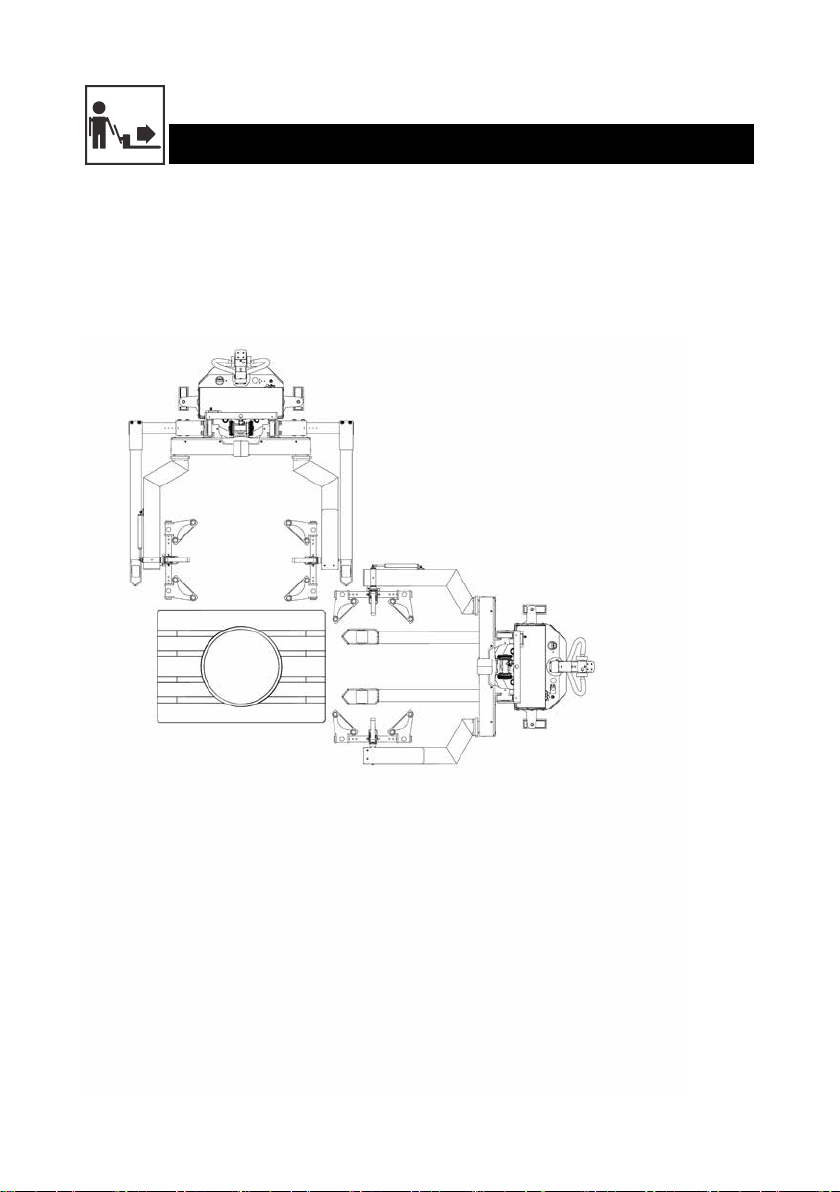
2.0 Functions and identications .......................................................................... 5
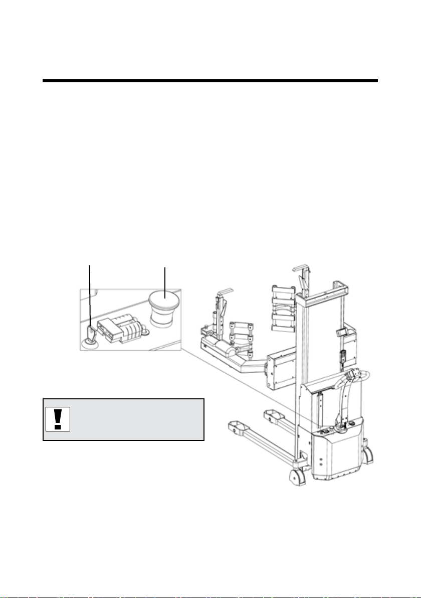
3.0 How to operate Multi drum turner ................................................................ 6
3.1 Handling of drums ............................................................................................................... 6
3.2 Use of the Multi drum turner................................................................................................ 7
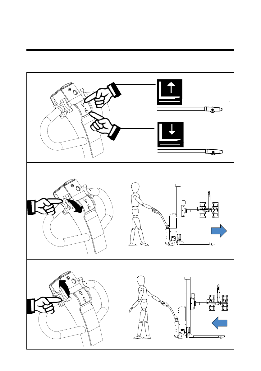
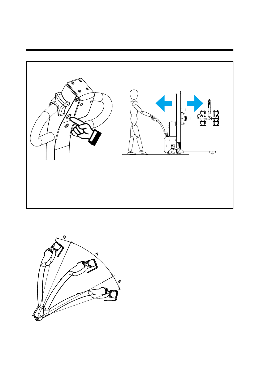
3.3 Handle functions.................................................................................................................. 8
3.4 Personal safety.................................................................................................................. 10
3.5 Remote control MR-1 / Lifting-Lowering-Rotation-Clamping..............................................11
3.6 Remote control / Lift and lower / Rotation ......................................................................... 12
3.7 Remote control / Clamping of drums................................................................................. 13
3.8 Remote control / Clamping of small drums and cans........................................................ 17
3.9 User-Interface LUI-1 Multi drum turner.............................................................................. 18
3.10 Setting up User-Interface LUI-1 Multi drum turner........................................................... 19
3.10.1 Home display................................................................................................................ 19
3.10.2 Display for Setup .......................................................................................................... 19
3.10.3 Setting of rotation speed............................................................................................... 20
3.10.4 Setting of stop position ................................................................................................. 20
3.10.5 Deleting stop positions ................................................................................................. 21
3.10.6 Setting the end stop limit for gripping arms (inner/outer).............................................. 21
3.10.7 Deleting end stop limit positions................................................................................... 22
3.11 Intended use .................................................................................................................... 23
3.12 Unintended use ............................................................................................................... 23
3.13 Unacceptable use............................................................................................................ 24
4.0 Optimum safety ..................................................................................................... 26
4.1 Safety regulations.............................................................................................................. 26
4.2 Rotation range................................................................................................................... 27
4.3 Driving loaded.................................................................................................................... 27
4.4 Rotation with load.............................................................................................................. 28
4.5 Emergency stop................................................................................................................. 28
4.6 Safety labels...................................................................................................................... 29
4.7 Additional safety advices ................................................................................................... 30
5.0 There must be a current supply... ............................................................... 31
5.1 Fuses - replacement.......................................................................................................... 31
5.2 Wirring connections........................................................................................................... 31
6.0 Maintenance............................................................................................................ 32
6.1 Cleaning ............................................................................................................................ 32
7.0 Good service after purchase ......................................................................... 33
7.1 Ordering spare parts.......................................................................................................... 33
7.2 Warranty/Compensation.................................................................................................... 33
7.3 Service and repair ............................................................................................................. 33
7.4 Warranty ............................................................................................................................ 33
7.5 Liability exemption............................................................................................................. 33

4
• Proper application
• Physical limitations of the product
• Risks with improper use
The Multi drum turner is manufactured in accordance with safety directives.
Among the subjects dealt with in this Instruction Manual are:
Therefore please read this Instruction Manual carefully!
1.0 Before the rst lift...

5
19
18
17
16
15
14
13
12
11
10
9
8
7
6
5
43
2
1
1. Handle
2. Lift/Lower
3. Horn
4. Forward/Reverse
5. Safety switch
6. Multiex function
7. Carriage
8. Clamp
9. Gripping arm
10. Height adjustment pipe
11. Top lock
12. Locking plate
13. Type plate, serial number
14. Emergency stop
15. Charger plug (external charger)
16. Ignition key
17. Battery indicator/hour counter
18. Remote control
19. User-Interface
2.0 Functions and identications

6
SELFMDT
SELFSMDT
3.1 Handling of drums
Handling of drums on closed pallets
- Use the Multi drum turner with straddle legs!
3.0 How to operate Multi drum turner

7
2
1
Note!!! Emergency stop (2)
must not be activated
3.2 Use of the Multi drum turner
Conditions for rotation: Center of the gripping arms is lifted at least: 430 mm
The load can be rotated 360°.
Insert key (1) and turn clockwise to switch on control current ready for function
activation.
3.0 How to operate the Multi drum turner

8
A
C
D
A
C
D
A
C
D
3.3 Handle functions
3.0 How to operate the Multi drum turner

9
The control functions of the Multi drum
turner are located in the handle
- The functions are dependent on
the positions of the handle!
Position A: Drive position
Drive current on
Brake deactivated
Position B: Stop/Brake/ Emergency Stop
Drive current o
Brake activated
Multiex-function
• This function makes it possible to drive the Multi drum turner, even though the
handle is in its upright, braked position (B)
• The function requires two-handed operation, i.e. it must be performed deliberately
• The function facilitates manoeuvring in conned areas.
Multiex-function
3.0 How to operate the Multi drum turner

10
3.4 Personal safety
The safety switch on the end of the handle ensures that the operator cannot be
trapped when the Multi drum turner is reversed.
When the safety switch is activated, the Multi drum turner will change
direction, move forwards and stop.
3.0 How to operate the Multi drum turner

11
3.5 Remote control MR-1 / Lifting-Lowering-Rotation-Clamping
The remote control is used for:
• Lifting/lowering the carriage/load
• Rotating the clamps/load
• Clamping/xing the load
• Releasing the load
• Moving the gripping arms horizontally
3.0 How to operate the Multi drum turner

12
NOTE!
Check that the load is placed in the load center and is
properly locked before rotating.
3.6 Remote control / Lift and lower / Rotation
Press (A) to lift.
Press (B) to lower.
Rotation:
Press to rotate in the direction of the arrow
The rotation is set to rotate continuously from the
factory.
The load can be rotated 360°.
3.0 How to operate the Multi drum turner
NOTE! The lowering height with remote control is set
from factory - 430 mm to the middle of the gripping arms.

13
The height is adjusted, so that the clamps (8) are placed approx. 5 cm above the
middle of the drum, and the top lock (11) is moved to upper position.
The clamps (8) are adjusted to the drum diameter.
The height adjustment pipe (10) is adjusted so that the locking plate (12) is placed a
little above the edge of the drum.
3.7 Remote control / Clamping of drums
3.0 How to operate the Multi drum turner

14
3.0 How to operate the Multi drum turner
Clamp slightly around the drum, and lower the gripping arms (9), until the locking
plate (12) locks at the edge of the drum.
Close the gripping arms (9) to fully and safely clamp the drum.
The top lock (11) is adjusted to the top of the drum and is tightened.
(8, 9, 10, 11, 12 - please check 2.0 Functions and Identications.)

15
3.0 How to operate the Multi drum turner
Press “Clamp” until
the drum is safely
xed.
Press “Release”
and “Lock button”
simultaneously to
open the gripping
arms.
Clamping:
Releasing:
If “soft drums” are to be handled and a liquid to be poured out of
the drum when reversed, take o the lid before clamping the drum.
An overpressure may occur that might cause spraying out liquid.

16
3.0 How to operate the Multi drum turner
Larger drums HAVE TO be secured with “Drum top lock”.
Smaller drums SHOULD be secured with “Drum top lock“.
Small drums and cans are NOT secured with the “Drum top locks“.
If using small drums and cans, remove “Drum top lock”.
If using larger drums If using smaller drums and cans

17
3.0 How to operate the Multi drum turner
3.8 Remote control / Clamping of small drums and cans
The gripping arms (9) in open position are placed around the drum/can.
The clamps (8) are adjusted to the size (diameter) of the drum/can.
Clamp around the drum/can.
(8, 9 - please check 2.0 Functions and Identications.)

18
3.0 How to operate the Multi drum turner
3.9 User-Interface LUI-1 Multi drum turner
User-Interface LUI-1 for:
• Setting speed for rotation
• Setting up to three stop position/angles in both rotation directions
• Setting end stop limit for gripping arms (inner/outer)

19
1.
2.
3.
1. 2.
3.
4.
5.
6.
3.0 How to operate the Multi drum turner
3.10 Setting up User-Interface LUI-1 Multi drum turner
3.10.1 Home display
When starting the machine/deactivating of emergency stop in User-Interface LUI-1,
home display is shown.
1. Position of gripping arms
- With green arrow - horizontal (0°)
- With red arrow - programmed angle
2. Limit
- Shown if the gripping arms are
placed in end stop limit position
(inner/outer), and if the gripping
arms can not be moved further.
3. Settings
3.10.2 Display for Setup
At home display, press Setup and the following is shown.
1. Speed (SPEED)
2. Angle stop (STOPS)
3. End stop limit (LIMIT)
4. Output data (LOG)
5. Home display (HOME)
6. Service (SERVICE)

20
3.0 How to operate the Multi drum turner
3.10.3 Setting of rotation speed
At the Setup display, press “SPEED” and the following is shown.
1. Use ➕⁄➖to adjust the speed.
2. Use ✔/✖to accept/cancel the
choice and return to Setup display.
3.10.4 Setting of stop position
From the factory, the clamps are set to rotate continuously. When the gripping arms
have rotated 360°, the machine stops rotating. If you want rotation to continue, it is
necessary to release/press the rotation switch on the remote control again.
It is possible to set up to three stop positions/angles for rotation in both directions.
If the machine is set with one or more stop positions/angles, the machine cannot
rotate further than the last set stop position/angle.
At home display, press Setup, and
afterwards STOPS, and the following is
shown.
This manual suits for next models
1
Table of contents
Other logitrans Industrial Equipment manuals
Popular Industrial Equipment manuals by other brands

Thermopatch
Thermopatch NL-15 R/SQR MAMMOTH user manual

MARBURG INDUSTRIES
MARBURG INDUSTRIES M500 owner's manual

Traub
Traub TNL12.2 operating instructions

Festo Pneumatic
Festo Pneumatic EB-145-60 operating instructions

Tyco Electronics
Tyco Electronics DT-3000 Customer's manual

Siemens
Siemens SIRIUS 3RK1901-1MX02 Original operating instructions