LONCIN HomeSite Power LC5000-AS User manual

Service Manual
HomeSite Power
LC5000-AS LC5000D-AS
LC6500-AS LC6500D-AS
LC8000-AS LC8000D-AS
Portable Generator Set
Loncin Motor Co., LTD

SAFETY PRECAUTIONS
a
Thoroughly read the OPERATOR’S MANUAL
before operating the generator set. Safe
operation and top performance can only be
attained when equipment is operated and
maintained properly.
The following symbols, found throughout this
manual, alert you to potentially dangerous
conditions to operators, service personnel and
equipment.
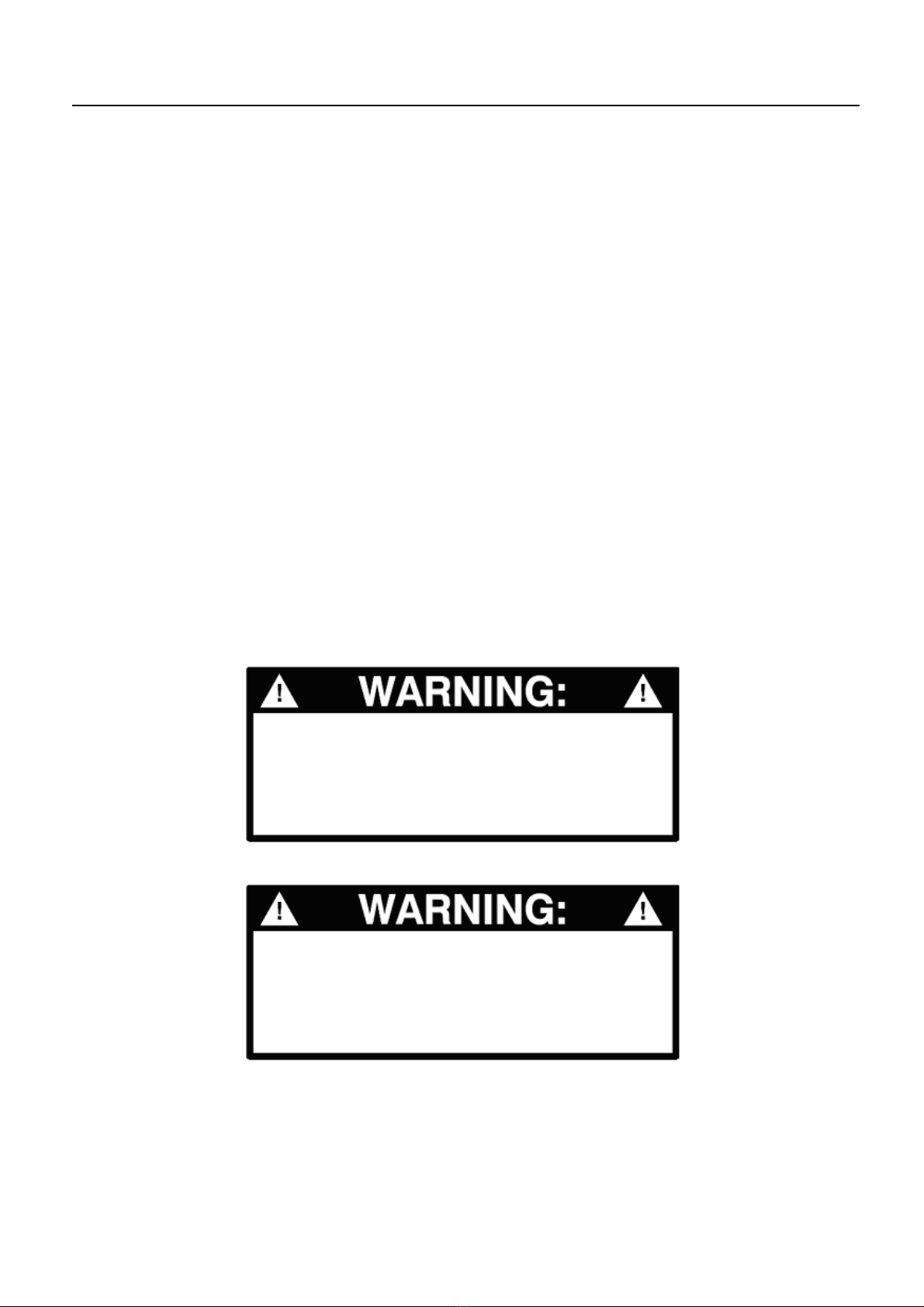
This symbol alerts you to an
immediate hazard that will result in severe
personal injury or death.
This symbol alerts you to a
hazard or unsafe practice that can result in
severe personal injury or death.
This symbol alerts you to a
hazard or unsafe practice that can result in
personal injury or damage to equipment or
property.
Electricity, fuel, exhaust, moving parts and
batteries present hazards against which
precautions must to taken to prevent severe
personal injury or death.
Exhaust Gas Is Deadly
•Operate the generator set outdoors only.
Stay away from the exhaust outlet.
•Make sure generator set exhaust will not
enter windows, doors, vents or air intakes of
adjacent buildings, vehicles or boats.
•NEVER USE THE GENERTOR SET
INSIDE a home, garage, crawl space,
barn, shed, cabin, boat, boat house, RV or
tent, or in a confined outdoor space such as
an alley, ditch, parking garage or courtyard,
or in any other space where exhaust can
accumulate. Note that HAZARDOUS
CARBON MONOXIDE LEVELS FROM
ENGINE EXHAUST CAN ACCUMULATE
INDOORS EVEN WHEN ALL WINDOWS
AND DOORS ARE OPEN AND FANS ARE
RUNNING.
Gasoline is Flammable / Explosive
•Refuel the generator set outdoors only.
•Static electric sparks caused by fuel flowing
through a service station pump nozzle can
ignite gasoline. Never fill the generator set
with a service station pump nozzle. Instead,
fill a safety tank sitting on the ground and
then slowly transfer fuel to the generator set
from the safety tank.
•DO NOT fill fuel tanks while the engine is
running. A hot engine can ignite the fuel.
•To prevent fire due to fuel leakage, always
close the fuel valve and let the generator set
cool before transporting it or storing it in a
confined space.
•DO NOT SMOKE OR ALLOW AN OPEN
FLAME near the generator set. Keep flames,
sparks, electrical switches, pilot lights,
electrical arcs, arc-producing equipment and
all other sources of ignition well away.
Generator Voltage is Deadly
•DO NOT CONNECT THE GENERATOR
SET DIRECTLY TO ANY BUILDING
ELECTRICAL SYSTEM. Back-feed could
cause electrocution of utility line workers and
damage to equipment. An approved
switching device must be used to prevent
interconnections. A trained and experienced
electrician must make electrical connections
when the generator set is used for
emergency power.
•Make sure clothing, shoes and skin are dry
when handling electrical equipment.
• Never operate the generator set in rain or
snow or when it is sitting on wet ground.
Moving Parts Can Cause Severe
Personal Injury or Death
•Before performing any maintenance on the
generator set, disconnect the spark plug wire
and the negative (–) cable of the battery to
prevent accidental starting.
• Always keep hands away from moving parts.
•Do not wear loose clothing or jewelry while
servicing the generator set. Loose clothing
and jewelry can become caught in moving
parts. Jewelry can short out electrical
contacts causing sparks, flame and electrical
shock.

SAFETY PRECAUTIONS
b
•Make sure that fasteners and clamps on the
generator set are tight. Keep guards in
position over fans, rotors, etc.
Battery Gases are explosive
•Wear safety glasses when servicing
batteries.
•Do not smoke.
•To reduce arcing when disconnecting or
reconnecting battery cables, always
disconnect the negative (–) cable of the
battery first and reconnect it last.
General Precautions
•Keep children away from the generator set.
•Wear hearing protection when near an
operating generator set.
•Keep a multi-class ABC fire extinguisher
readily at hand. Class A fires involve
ordinary combustible materials such as
wood and cloth. Class B fires involve
combustible and flammable liquids and
gaseous fuels. Class C fires involve live
electrical equipment. (ref. NFPA No. 10)
•Benzene and lead may be found in gasoline
and have been identified by some state and
federal agencies as causing cancer or
reproductive toxicity. Do not ingest, inhale or
contact gasoline.
•Used engine oils have been identified by
some state and federal agencies as causing
cancer or reproductive toxicity. Do not ingest,
inhale or contact used engine oil or its
vapors.
•Keep the generator set clean and dry at all
times. Excess grease and oil can catch fire
and/or accumulate dirt, which can cause
overheating.
•Do not store anything on the generator set,
such as oil cans, oily rags, chains or wooden
blocks. A fire could result or operation could
be adversely affected
•Do not work on the generator set when you
are mentally or physically fatigued or have
consumed alcohol or drugs.
Failure to properly follow instructions and precautions can cause
you to be seriously hurt or killed.
Follow the procedures and precautions in this manual carefully.
Improper service or repairs can create an unsafe condition that
can cause your customer or others to be seriously hurt or killed.
Follow the procedures and precautions in this manual and other
service materials carefully.

TABLE OF CONTENTS
c
SECTION 1 INTRODUCTION
1-1 Generator Components .............................................................. 1
1-2 Specifications ...................................................................... 2
SECTION 2 DIMENSIONS AND TORQUE
2-1 Engine Dimensions ................................................................. 3
2-2 Generator Dimensions ............................................................... 7
2-3 Torque Specification ................................................................ 8
2-4 Standard Torques Specification ....................................................... 8
SECTION 3 MAINTENANCE
3-1 Maintenance Schedule .............................................................. 9
3-2 Engine Oil ........................................................................ 10
3-3 Air Cleaner ....................................................................... 11
3-4 Fuel Sediment Cup Cleaning ........................................................ 12
3-5 Spark Arrester ..................................................................... 12
3-6 Spark Plug ........................................................................ 13
3-7 Valve Clearance ................................................................... 14
3-8 Governor ......................................................................... 14
SECTION 4 DISASSEMBLY AND SERVICE
4-1 Troubleshooting.................................................................... 15
4-1-1 Hard Starting .................................................................. 15
4-1-2 Low Power .................................................................... 16
4-1-3 Speed Unstable ................................................................ 17
4-1-4 Low Speed Voltage ............................................................. 18
4-1-5 Exhaust Color Abnormal ........................................................ 19
4-1-6 No AC Output Voltage .......................................................... 20
4-1-7 No DC Output Voltage .......................................................... 20
4-2 Preparing to Service ................................................................ 21
4-2-1 Safety Considerations .......................................................... 21
4-2-2 Special Tools .................................................................. 21
4-3 Disassembly Char .................................................................. 22

TABLE OF CONTENTS
d
4-4 Engine ............................................................................ 23
4-4-1 Crankshaft / Pistion ............................................................. 25
4-4-2 Flywheel / Starter Motor ......................................................... 29
4-4-3 Cylinder head / Valves .......................................................... 33
4-4-4 Recoil Starter / Fan Cover ....................................................... 37
4-4-5 Air Cleaner .................................................................... 40
4-4-6 Carburetor .................................................................... 41
4-5 Generator ......................................................................... 42
4-5-1 Fuel Tank ..................................................................... 42
4-5-2 Muffler ........................................................................ 43
4-5-3 Generator ..................................................................... 44
4-5-4 Control Panel .................................................................. 48
SECTION 5 WIRING DIAGRAMS ......................................................... 54

SECTION 1. INTRODUCTION
- 1 -
DC
PROTECTOR
1-1 Generator Components
FIGURE 1. 5000/6500/8000AS COMPONENT LOCATIONS
MUFFLER
SPARK
PLUG BOOT
FUEL
V
ALVE
DC OUTPUT
CHOKE
LEVE
R
AIR CLEANER
STARTER GRIP
FUEL GAUGE
FUEL TANK CAP
GROUND
TERMINAL
AC CIRCUIT
BREAKER
AC BREAKER
RESET
AC BREAKER
RESET
ENGINE SWITCH
OUTPUT
INDICATOR

SECTION 1. INTRODUCTION
- 2 -
1-2 Specifications
GENERATOR LC5000-AS/LC5000D-AS LC6500-AS/LC6500D-AS LC8000-AS/LC8000D-AS
Engine model LC188F / LC188FD LC188F / LC188FD LC190F-1 / LC190FD-1
Engine type Single cylinder,4stroke, forced cooling ,OHV
Power output 8.2Kw/3600rpm 8.2Kw/3600rpm 9.0Kw/3600rpm
Bore×Stroke 88mm×64 mm 88mm×64mm 90mm×66mm
Displacement 389cc 389cc 420cc
Compression ratio 8.0∶1 8.0∶1 8.3∶1
Oil capacity 1.1L(0.29gal)1.1L(0.29gal)1.1L(0.29gal)
Fuel tank capcity 25L(6.6gal)25L(6.6gal)25L(6.6gal)
Fuel consumption ≤374g/Kw.h
Continuing time 9h 9h 8h
Rated frequency 50 Hz/60 Hz
Rated voltage 110V/115V/120V/220V/ 230V/240
Voltage regulator
system Automatic Voltage Regulation
Rated output 4.0Kw 5.0Kw 6.0Kw
Max output 4.5Kw 5.5Kw 6.5Kw
Power factor 1.0 1.0 1.0
Charging voltage 12V(DC) 12V(DC) 12V(DC)
Charging current 8.3A(DC) 8.3A(DC) 8.3A(DC)
Starting system Recoil start/Electic-start
Lgnition system Transistorized magneto ignition
Noise(≤7m)≤76dB(A) ≤76dB(A) ≤76dB(A)
Dimension 681×546×566 681×546×566 681×546×566
Net weight 78Kg/83Kg 80Kg/85Kg 85Kg/90 Kg

SECTION 2. DIMENSIONS AND TORQUES
- 3 -
2-1 Engine Dimensions
LC5000/6500
Part Item Factory Specification Allowable limit
Engine Maximum speed 3850±150 rpm -
Cylinder compression 5.0-8.0 kg/cm2
at 600 rpm -
Cylinder Sleeve I.D. 88.00 mm
(3.465 in)
88.17 mm
(3.471 in)
Cylinder head Warpage - 0.10 mm
(0.004 in)
Piston Skirt O.D. 87.985 mm
(3.464 in)
87.85 mm
(3.459 in)
Piston-to-cylinder
clearance
0.015-0.052 mm
(0.0006-0.0020 in)
0.12 mm
(0.005 in)
Piston pin bore I.D. 20.002 mm
(0.7875 in)
20.042 mm
(0.7891 in)
Pin O.D. 20.00 mm
(0.787 in)
19.95 mm
(0.785 in)
Piston -to- piston pin bore
clearance
0.002-0.014 mm
(0.0001-0.0006 in)
0.08 mm
(0.003 in)
Piston rings Ring side clearance
Top/second/oil
0.030-0.060 mm
(0.0012-0.0024 in)
0.15 mm
(0.0006 in)
Ring end gap
Top/second
Oil
0.2-0.4 mm
(0.01-0.02 in)
1.0 mm
(0.04 in)
Ring Width Top/second
Oil
2.0 mm
(0.08 in)
2.8 mm
(0.110 in)
1.75 mm
(0.069 in)
2.7 mm
(0.106 in)
Connecting
rod
Small end I.D.
(Pin End)
20.005 mm
(0.7876 in)
20.07 mm
(0.790 in)
Big end I.D.
(Crankshaft)
36.025 mm
(1.4183 in)
36.07 mm
(1.420 in)
Big end oil clearance 0.040-0.066 mm
(0.0016-0.0026 in)
0.12 mm
(0.005 in)
Big end side clearance 0.1-0.7 mm
(0.004-0.028 in)
1.0 mm
(0.04 in)
Crankshaft
Crankshaft O.D.
(Connecting rod Large
end)
35.985 mm
(1.4167 in)
35.93 mm
(1.415 in)

SECTION 2. DIMENSIONS AND TORQUES
- 4 -
LC5000/6500
Part Item Factory Specification Allowable limit
Valves Valve Lash IN
0.10±0.02 mm
(0.004±0.001 in) -
EX 0.15±0.02 mm
(0.006±0.001in) -
StemO.D. IN
6.59 mm
(0.259 in)
6.44 mm
(0.254 in)
EX 6.55 mm
(0.258 in)
6.40 mm
(0.252 in)
GuideI.D. IN/EX 6.60mm
(0.260 in)
6.66 mm
(0.262 in)
Stem clearance IN
0.010-0.040 mm
(0.0004-0.0016 in)
0.11mm
(0.004 in)
EX 0.050-0.080 mm
(0.0020-0.0031 in)
0.13 mm
(0.005 in)
Seat width 1.1 mm
(0.04 in)
2.0mm
(0.08 in)
Spring free length 39.0 mm
(1.54 in)
37.5 mm
(1.48 in)
Camshaft Cam height IN 32.40-32.80 mm
(1.276-1.291 in)
32.25mm
(1.270 in)
EX 31.89-32.29 mm
(1.256-1.271 in)
31.75 mm
(1.250 in)
Camshaft O.D. 15.984 mm
(0.6293 in)
15.92 mm
(0.627 in)
Crankcase
cover
Camshaft-Bearing I.D. 16.0 mm
(0.63 in)
16.05 mm
(0.632 in)
Spark plug Gap 0.7-0.8 mm
(0.028-0.031 in) -
Ignition coil Resistance Primary coil 0.8-1.0 Ω-
Secondary coil 5.9-7.1 KΩ-
Air gap (at flywheel) 0.4±0.2 mm
(0.016±0.008 in) -

SECTION 2. DIMENSIONS AND TORQUES
- 5 -
LC8000
Part Item Factory Specification Allowable limit
Engine Maximum speed 3850±150 rpm -
Cylinder compression 5.0-8.0 kg/cm2
at 600 rpm -
Cylinder Sleeve I.D. 90.00 mm
(3.543 in)
90.17 mm
(3.550 in)
Cylinder head Warpage - 0.10 mm
(0.004 in)
Piston Skirt O.D. 89.985 mm
(3.543 in)
89.85 mm
(3.537 in)
Piston-to-cylinder
clearance
0.015-0.052 mm
(0.0006-0.0020 in)
0.12 mm
(0.005 in)
Piston pin bore I.D. 20.002 mm
(0.7875 in)
20.042 mm
(0.7891 in)
Pin O.D. 20.00 mm
(0.787 in)
19.95 mm
(0.785 in)
Piston -to- piston pin bore
clearance
0.002-0.014 mm
(0.0001-0.0006 in)
0.08 mm
(0.003 in)
Piston rings Ring side clearance
Top/second/oil
0.030-0.060 mm
(0.0012-0.0024 in)
0.15 mm
(0.0006 in)
Ring end gap
Top/second
Oil
0.2-0.4 mm
(0.01-0.02 in)
1.0 mm
(0.04 in)
Ring Width Top/second
Oil
2.0 mm
(0.08 in)
2.8 mm
(0.110 in)
1.75 mm
(0.069 in)
2.7 mm
(0.106 in)
Connecting
rod
Small end I.D.
(Pin End)
20.005 mm
(0.7876 in)
20.07 mm
(0.790 in)
Big end I.D.
(Crankshaft)
36.025 mm
(1.4183 in)
36.07 mm
(1.420 in)
Big end oil clearance 0.040-0.066 mm
(0.0016-0.0026 in)
0.12 mm
(0.005 in)
Big end side clearance 0.1-0.7 mm
(0.004-0.028 in)
1.0 mm
(0.04 in)
Crankshaft
Crankshaft O.D.
(Connecting rod Large
end)
35.985 mm
(1.4167 in)
35.93 mm
(1.415 in)

SECTION 2. DIMENSIONS AND TORQUES
- 6 -
LC8000
Part Item Factory Specification Allowable limit
Valves Valve Lash IN
0.10±0.02 mm
(0.004±0.001 in) -
EX 0.15±0.02 mm
(0.006±0.001in) -
StemO.D. IN
6.59 mm
(0.259 in)
6.44 mm
(0.254 in)
EX 6.55 mm
(0.258 in)
6.40 mm
(0.252 in)
GuideI.D. IN/EX 6.60mm
(0.260 in)
6.66 mm
(0.262 in)
Stem clearance IN
0.010-0.040 mm
(0.0004-0.0016 in)
0.11mm
(0.004 in)
EX 0.050-0.080 mm
(0.0020-0.0031 in)
0.13 mm
(0.005 in)
Seat width 1.1 mm
(0.04 in)
2.0mm
(0.08 in)
Spring free length 39.0 mm
(1.54 in)
37.5 mm
(1.48 in)
Camshaft Cam height IN 32.40-32.80 mm
(1.276-1.291 in)
32.25mm
(1.270 in)
EX 31.89-32.29 mm
(1.256-1.271 in)
31.75 mm
(1.250 in)
Camshaft O.D. 15.984 mm
(0.6293 in)
15.92 mm
(0.627 in)
Crankcase
cover
Camshaft-Bearing I.D. 16.0 mm
(0.63 in)
16.05 mm
(0.632 in)
Spark plug Gap 0.7-0.8 mm
(0.028-0.031 in) -
Ignition coil Resistance Primary coil 0.8-1.0 Ω-
Secondary coil 5.9-7.1 KΩ-
Air gap (at flywheel) 0.4±0.2 mm
(0.016±0.008 in) -

SECTION 2. DIMENSIONS AND TORQUES
- 7 -
2-2 Generator Dimensions
50HZ 20℃
5000 (4kW)
Part Item Factory specification
Main winding (Br / W) Resistance 0.8-0.98 Ω
Secondary winding (Bu / Bu) Resistance 1.63-2.07 Ω
Field winding Resistance 44.55-54.45Ω
DC winding (G / G) Resistance 0.11-0.16 Ω
Carbon brush Brush length 5-9 mm
6500 (5kW)
Part Item Factory specification
Main windingⅠ(Br / W) Resistance 0.50-0.61 Ω
Exciter winding (Bu / Bu) Resistance 1.90-2.31 Ω
Field winding Resistance 47.88-58.52 Ω
DC winding (G / G) Resistance 0.11-0.16 Ω
Carbon brush Brush length 5-9 mm
Battery Specific gravity of
electrolyte 1.270-1.290
8000 (6kW)
Part Item Factory specification
Main windingⅠ(Br / W) Resistance 0.43-0.53 Ω
Exciter winding (Bu / Bu) Resistance 1.96-2.36 Ω
Field winding Resistance 48.25-59.88 Ω
DC winding (G / G) Resistance 0.13-0.18 Ω
Carbon brush Brush length 5-9 mm
Battery Specific gravity of
electrolyte 1.270-1.290

SECTION 2. DIMENSIONS AND TORQUES
- 8 -
2-3 Torque Specification
2-4 Standard Torques Specification
Part Fastener size Torque values N· m (kg· cm, lb·ft)
Cylinder head bolt 10×1.25×80 mm 32-38 (320-380, 23.1-28.5)
Pivot bolt 6×0.5 mm 8-12 (80-120, 5.8-8.7)
Pivot adjusting nut 8×1.25 mm 22-26 (220-260, 15.9-18.8)
Crankcase cover bolt 8×1.25×35 mm 22-26 (220-260, 15.9-18.8)
Connecting rod bolt 8×1.25 mm 12-16 (120-160, 8.7-11.5)
Air cleaner wing nut 6×1.0 mm 7-10 (70-100, 5.1-7.2)
Air cleaner mounting nut 6×1.0 mm 7-10 (70-100, 5.1-7.2)
Muffler mounting bolt 8×1.25 mm 20-28 (200-280, 14.5-20.2)
Oil drain bolt 12×1.5 mm 20-25 (200-250, 14.5-18.1)
Fuel tank mounting bolt/ nut 6×1.0 mm 8-12 (80-120, 5.8-8.7)
Fuel valve joint nut 10×1.25 mm 20-25 (200-250, 14.5-18.1)
Oil level switch mounting nut 10×1.25 mm 8-12 (80-120, 5.8-8.7)
Flywheel mounting nut 16×1.5 mm 110-120 (1100-1200, 79.5-86.8)
Starter solenoid terminal nut 6×1.0 mm 3.0-4.5 (30-45, 2.2-3.3)
Standard torque values
5 mm bolt, nut 4-7 (40-70, 2.9-5.1)
6 mm bolt, nut 8-12 (80-120, 5.8-8.7)
8 mm bolt, nut 20-28 (200-280, 14.5-20.2)
10 mm bolt, nut 35-40 (350-400, 14.5-20.2)
12 mm bolt, nut 50-60 (500-600, 36.2-43.4)

SECTION 3. MAINTENANCE
- 9 -
3-1 Maintenance Schedule
Periodic maintenance is essential for top
performance. Use Table 3 as a guide. Under hot or
dusty operating conditions some maintenance
operations should be performed more frequently,
as indicated by the footnotes in the table.
Keep a log of maintenance performed and the
hours run. Recording maintenance will help you
keep it regular and provide a basis for supporting
warranty claims.
Accidental starting of the generator
set during maintenance can cause severe
personal injury or death. Before performing
maintenance, disconnect the spark plug wire
from the spark plug.
A hot generator set can cause
severe burns. Always allow the generator set
to cool before performing any maintenance or
service.
TABLE 3. PERIODIC MAINTENANCE SCHEDULE
1.See GENERAL INSPECTIONS on OPREATOR’S MANUAL page 15.
2.Service more frequently when used in dusty environments.
3. These items must be performed by a trained and experienced mechanic (authorized Onan dealer).
SERVICE ITEMS
SERVICE INTERVAL
EACH
USE
FIRST
MONTH OR
20 HOURS
EVERY 3
MONTHS OR
50 HOURS
EVERY
MONTH
EVERY 6
MONTHS OR
100 HOURS
EVERY
YEAR OR
300 HOURS
General Inspection X1
Check Oil Level X
Test GFCI X
Change Engine Oil X X
Clean Air Cleaner X2
Clean Cylinder Cooling Fins X2
Clean Spark Plug X
Clean the Spark Arrestor X
Clean Fuel Sediment Cup X3
Clean Fuel Tank X3
Adjust Valve Clearance X3
Check fuel line Every 2 years(Replace if necessary) 3

SECTION 3. MAINTENANCE
- 10 -
3-2 Engine Oil
NOTE: Drain the oil while the engine is still
warm to assure rapid and complete draining.
1) Remove the oil fill cap and drain plug.
2) Drain the oil from the crankcase.
3) Reinstall the drain plug securely.
4) Add new oil up to the bottom edge of the oil fill
hole with the engine stopped and in a level
position.
5) Reinstall the oil fill cap and tighten it securely.
NOTE: Check the oil level BEFOR EACH USE with
the generator on a level surface with the engine
stopped.
1. Remove the oil filler cap and wipe the dipstick
clean.
2. Check the oil level by inserting the dipstick into
the filler neck without screwing it in.
3. If the level is low, add the recommended oil to
the upper mark on the dipstick.
Used motor oil may cause skin
cancer if repeatedly left in contact with the skin
for prolonged periods. Thoroughly wash your
hands with soap and water as soon as possible
after handling used oil.
Engine Oil Capacity 1.16 US qt (1.1 L)
Oil fill cap Oil drain bolt (M12)
Lower level
RECOMMENDED ENGINE OIL:
SAE 10W-30 is recommended for general, all
temperature use: service classification
SG·SF/CC·CD.
20W-40
10W-30
10W-40
20W-50
Ambient temperature

SECTION 3. MAINTENANCE
- 11 -
3-3 Air Cleaner
A dirty air cleaner will restrict air flow
to the carburetor. To prevent carburetor
malfunction, service the air cleaner regularly.
Service more frequently when operating the
generator in extremely dusty areas.
Using gasoline or flammable
solvent to clean the filter element can cause a
fire or explosion. Use only soapy water or
nonflammable solvent.
Never run the generator without the
air cleaner. Rapid engine wear will result.
1) Remove the cleaner cover by unsnapping the
two spring clips. Clean more often in dusty
environments
2) Remove the two foam filter elements and
thoroughly wash them with soap and water. Let
them dry thoroughly.
3) Knead in 1 teaspoon (5 cm3) of clean engine oil
into each foam filter element. The oil should be
distributed evenly throughout each filter
elements.
4) Reinstall the filter elements, the gray filter first
(finer pores) and then the black filter (larger
pores).
5) Secure the cover with the spring clips.
AIR CLEANER COVER
CLIP
AIR CLEANER ELEMENT
Soa
p
+ Wate
r
DRY
ENGINE OIL
S
Q
UEEZE

SECTION 3. MAINTENANCE
- 12 -
3-4 Fuel Sediment Cup Cleaning
The sediment cup prevents dirt or water which may
be in the fuel tank from entering the carburetor. If
the engine has not been run for a long time, the
sediment cup should be cleaned.
1) Turn the fuel valve to the OFF position.
Remove the sediment cup, and o-ring.
2) Clean the sediment cup, and o-ring, in
nonflammable or high flash point solvent.
3) Reinstall o-ring, and sediment cup.
4) Turn the fuel valve ON and check for leaks.
Gasoline is extremely flammable
and is explosive. Do not smoke or allow flames
or sparks in the area.
After reassembly, check for leaks,
and make sure the area is dry before starting
the engine.
3-5 Spark Arrester
A hot muffler can cause severe
burns. Allow the generator set to cool before
servicing the muffler.
Refer to MAINTENANCE SCHEDULE for
scheduled spark arrester cleaning. After letting the
generator set cool down, remove the spark arrester
screen. Inspect for damage, and replace if
defective. Clean any deposits on the screen with a
wire brush. Reinstall the spark arrester, and tighten
the screw securely.
FUEL FILTER
SEDIMENT CUP
(10 mm)
FUEL VALVE
O-RING
SEDIMENT CUP
SPARK ARRESTOR
(Screw M4)

SECTION 3. MAINTENANCE
- 13 -
3-6 Spark Plug
To ensure proper engine operation, the spark plug
must be properly gapped and free of deposits.
If the engine has been running, the spark plug and
muffler will be very hot. Be careful not to touch the
muffler or spark plug.
1) Turn off generator.
2) Remove the spark plug cap.
3) Clean any dirt from around the spark plug
base.
4) Use the wrench supplied in the tool kit to
remove the spark plug.
5) Visually inspect the spark plug. Discard it if the
insulator is cracked or chipped. Clean the
spark plug with a wire brush if it is to be reused.
6) Measure the plug gap with a feeler gauge.
Correct as necessary by carefully bending the
side electrode.
The gap should be: 0.70-0.80 mm (0.028-0.031 in).
7) Check that the spark plug washer is in good
condition, and thread the spark plug in by hand
to prevent cross-threading.
8) After the spark plug is seated, tighten with a
spark plug wrench to compress the washer.
If installing a new spark plug, tighten l/2 turn
after the spark plug seats to compress the
washer. If reinstalling a used spark plug, tighten
l/8 - l/4 turn after the spark plug seats to
compress the washer.
The spark plug must be securely
tightened. An improperly tightened spark plug
could damage the engine.
Never use spark plugs which have
an improper heat range. Use only the
recommended spark plugs or equivalent.
PLUG WRENCH
PLUG CAP
0.7-0.80mm
SIDE
ELECTRODE METAL BRUSH
SPARK PLUG TORQUE
20N•m-25N•m

SECTION 3. MAINTENANCE
- 14 -
3-7 Valve Clearance
Valve clearance inspection and
adjustment must be performed with the engine
cold.
1) Remove the cylinder head cover, and set the
piston at top dead center of the compression
stroke (both valves fully closed). Pull the starter
until the piston is at top dead center of the
compression or exhaust stroke.
2) Insert a feeler gauge between the rocker arm
and valve to measure valve clearance.
3) If adjustment is necessary, proceed as follows:
a) Hold the rocker arm pivot and loosen the
pivot lock nut.
b) Turn the rocker arm pivot to obtain the
specified clearance.
c) Retighten the lock nut while holding the
rocker arm pivot.
d) Recheck valve clearance after tightening
the lock nut.
3-8 Governor
1) Take down the fuel tank.
2) Loosen the nut on the governor arm pinch bolt.
3) Move the arm until the throttle is completely
open, and hold it in that position.
4) Rotate the governor arm shaft as far as it will
go in same direction it was just moved by the
governor arm, and then tighten the governor arm
pinch bolt.
5) Whether Check the arm and throttle move
smoothing.
6) Install the fuel tank.
7) Start the engine and adjust the limiting screw to
produce the standard until the engine warm up to
normal operating temperature.
Standard valve
clearance
IN. 0.10±0.02 mm
(0.004±0.001 in)
EX. 0.15±0.02 mm
(0.006±0.001 in)
Idle speed 3600±150rpm
FEELER
GAUGE
GOVERNOR
SPRING
THR
O
TTLE
GOVERNOR
ARM SHAFT
GOVERNOR
ARM
ANTI-SURGE
SPRING
NUT
LIMITING
SCREW
GOVERNOR
ARM PINCH
BOLT
ROCKER ARM
PIVOT
To increase valve clearance, screw lock nut out.
To decrease valve clearance
,
screw lock nut in.
LOCK NUT
10N•m-140N•m

SECTION 4. DISASSEMBLY AND SERVICE
- 15 -
(TRY AGAIN AFTER A FEW MINUTES)
4-1 Troubleshooting
4-1-1 Hard Starting
(SEE 4-4-1)
(SEE 4-4-1)
(SEE 4-4-3)
(SEE 4-4-3)
(SEE 4-4-3)
(SEE 3-7)
(SEE 4-4-1)
(SEE 4-5-4)
(SEE 4-4-2)
(SEE 4-4-2)
(SEE 4-4-2)
(SEE 3-6)
(SEE 3-2)
HARD
STARING
FUEL SYSTEM
IGNITION
SYSTEM
COMPRESSION
SYSTEM
(SEE 3-3)
(SEE 4-4-6)
(SEE 3-4)
(ADD FUEL INTO FUEL TANK)
FUEL low
FUEL FILTER clo
gg
ed
CARBURETOR out of ad
j
ustment
A
IR FILTER dirt
y
OIL low
SPARK PLUG GAP incorrect
SPARK PLUG CAP fault
y
IGNITION COIL GAP incorrect
IGNITION COIL fault
y
START SWITCH fault
y
OIL ALERT SYSTEM fault
y
V
ALVE CLEARANCE incorrect
CYLINDER HEAD GASKET fault
y
CYLINDER HEAD BOLT fault
y
V
ALVE fault
y
CYLINDER / PISTON / PISTON RING worn
CAMSHAFT worn
ENGINE FLOODED to much fuel
This manual suits for next models
5
Table of contents
Other LONCIN Portable Generator manuals
Popular Portable Generator manuals by other brands

HERON
HERON 8896140 Translation of the original user manual

CORNING
CORNING Everon 6200 user manual

Energizer
Energizer EZG1600i-A-UK Original instructions

Generac Power Systems
Generac Power Systems MLG8 user manual

Marathon
Marathon MAGNAPLUS ATEX Zone 2 Installation, operation and maintenance manual

Milwaukee
Milwaukee M18 49-24-2371 manual