Table of Contents
1 / Safety Precautions
3
2 / Module Introduction5
3 / Modules Transpo and Storage10
4 / Unloading and Storage14
5 / Unpacking18
18
18
21
6 / Module Installation22
5
7
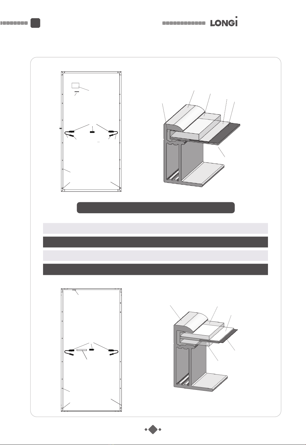
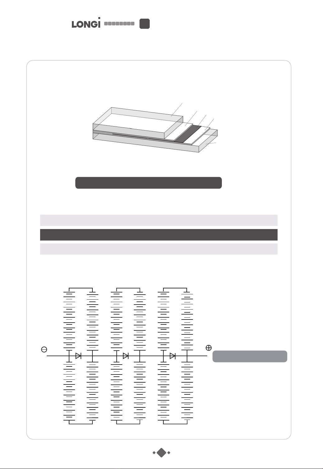
2.1 Schematic diagram of module structure
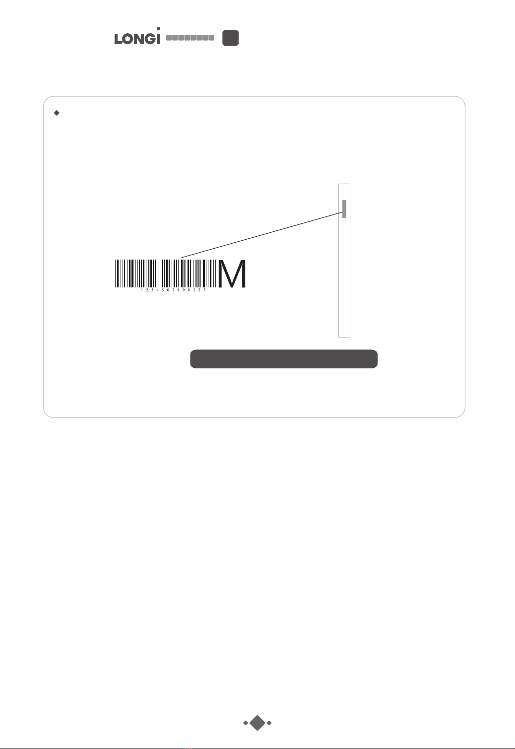
2.2 Module identication
5.1 Conrmation of mounting system before unpacking modules
5.2 Unpacking requirements
5.3 Unpacking steps
22
22
22
23
23
24
24
25
25
26
26
26
27
28
28
29
29
29
6.1 Storage precautions before installing modules
6.2 Precautions for handling modules prior to installation
6.3 General safety
6.4 Electrical peormance safety
6.5 Operation safety
6.6 Installation conditions
6.6.1 Installation site and working environment
6.6.2 Selection of tilt angle
6.7 Mechanical installation
6.8 Installation method
6.9 Electrical installation
6.9.1 Electrical peormance
6.9.2 Cables and wiring
6.9.3 Connecting cable
6.9.4 Bypass diodes
6.9.5 Safety of electrical connections
6.10 Grounding
6.10.1 Grounding clamp
10
13
3.1 Transpo and storage requirements
3.2 Notes on claims for cargo damage in transit