NF WF1973 User manual

MULTIFUNCTION GENERATOR
WF1973/WF1974
Instruction Manual (Basics)
NF Corporation

MULTIFUNCTION GENERATOR
WF1973/WF1974
Instruction Manual (Basics)
DA00016809-001
I
WF1973/WF1974
Preface
Thank you for purchasing the WF1973/WF1974 Multifunction Generator.
To ensure safe and proper use of this electric equipment, please read first Safety Precautions on
the following pages.
●Caution Symbols Used in This Manual
The following caution symbols are used in this manual. Be sure to observe these caution
symbols and their contents to ensure the safety of the user and avoid damage to the
equipment.
WARNING
This mark indicates information for the avoidance of a hazard such as electric
shock that may endanger human life or cause injury during handling of the
equipment.
CAUTION
This mark indicates information for the avoidance of damage to the equipment
during handling.
●This manual has the following chapter organization.
Instruction manuals of the WF1973/WF1974 are divided to two volumes, Basics and
Application. Instructions for remote control (GPIB and USB) are provided separately.
If reading this manual for the first time, start from 1. OVERVIEW of the Basics Instruction
Manual.
Basics
1. OVERVIEW
Briefly describes and explains the features and brief operation principles of the WF1973/
WF1974.
2. PREPARATIONS BEFORE USE
Describes various cautions regarding preparations to be made before using the WF1973/
WF1974, ranging from installation to connection of the power supply.
3. PANELS AND I/O TERMINALS
Describes the functions and operations of the switches and I/O terminals of the panel
controls.
4. BASIC OPERATION
Describes how to use basic functions.
5. SAVING AND RECALLING SETTINGS
Describes how to store and retrieve the settings.
6. LIST OF INITIAL SETTINGS
Describes initial settings.
7. SPECIFICATIONS
Lists the specifications (functions and performance) of the WF1973/WF1974.
Application
1. DETAILS OF PARAMETER-VARIABLE WAVEFORMS
Explains the meanings of each parameter of parameter-variable waveforms and
waveform examples.
2. CREATING ARBITRARY WAVEFORMS
Explains how to input and edit arbitrary waveforms from the panel control.

II MULTIFUNCTION GENERATOR
3. HANDY USE OF 2-CHANNEL DEVICE (WF1974 ONLY)
Explains how to operate two channels at the same time.
4. SYNCHRONIZING MULTIPLE UNITS
Describes how to configure a multi-phase oscillator by connecting multiple units of this
product.
5. USING EXTERNAL FREQUENCY REFERENCE
Describes how to use external frequency reference.
6. USING SEQUENCE OSCILLATION
Describes how to set and operate sequence oscillation.
7. USING USER-DEFINED UNITS
Explains the units that can be optionally set by users.
8. OTHER UTILITY SETTINGS
Explains how to set display and operational details.
9. TROUBLESHOOTING
Explains error messages and how to respond to cases where a failure is suspected.
10. MAINTENANCE
Explains the operational inspection and performance test.

III
WF1973/WF1974
Safety Precautions
To ensure safe use, be sure to observe the following warnings and cautions.
NF Corporation shall not be held liable for damages that arise from a failure to observe these
warnings and cautions.
This product is a Class I product (with protective conductor terminal) that conforms to the JIS and
IEC insulation standards.
●Be sure to observe the contents of this instruction manual.
This instruction manual contains information for the safe operation and use of this product.
Be sure to read this information first before using this product.
All the warnings in the instruction manual must be heeded to prevent hazards that may
cause major accidents.
●Be sure to ground the product.
This product uses a line filter and must be grounded to avoid the risk of electric shock.
To prevent electric shock, be sure to safely implement grounding such that ground resis-
tance is 100 Ω or lower.
The WF1973/WF1974 is automatically grounded when the 3-prong power plug is connected
to a 3-prong power outlet with a protective grounding contact.
This product does not come with a 3-prong to 2-prong conversion adapter. When using a
separately sold 3-prong to 2-prong conversion adapter, be sure to connect the (green)
grounding wire of the adapter to the grounding terminal next to the outlet.
●Check the power supply voltage.
This product operates on the power supply voltage shown in 2.3 Grounding and Power
Supply Connection in the Basics Instruction Manual.
Prior to connecting the power supply, check that the voltage of the power supply matches
the rated power supply of the product.
●In case of suspected anomaly
If this product emits smoke, an abnormal smell, or abnormal noise, immediately power it off
and stop using it.
If such an anomaly occurs, do not use this product until it has been repaired, and
immediately report the problem to the location of purchase (either NF Corporation or your
distributor).
●Do not use this product when gas is present.
An explosion or other such hazard may result.
●Do not remove the cover.
This product contains high-voltage parts. Absolutely never remove its cover.
Even when the inside of this product needs to be inspected, do not touch the inside. All such
inspections are to be performed by service technicians designated by NF Corporation.
●Do not modify this product.
Absolutely never modify this product, as this may cause new hazards and may disqualify
this product from repair in case of failure.
IV MULTIFUNCTION GENERATOR
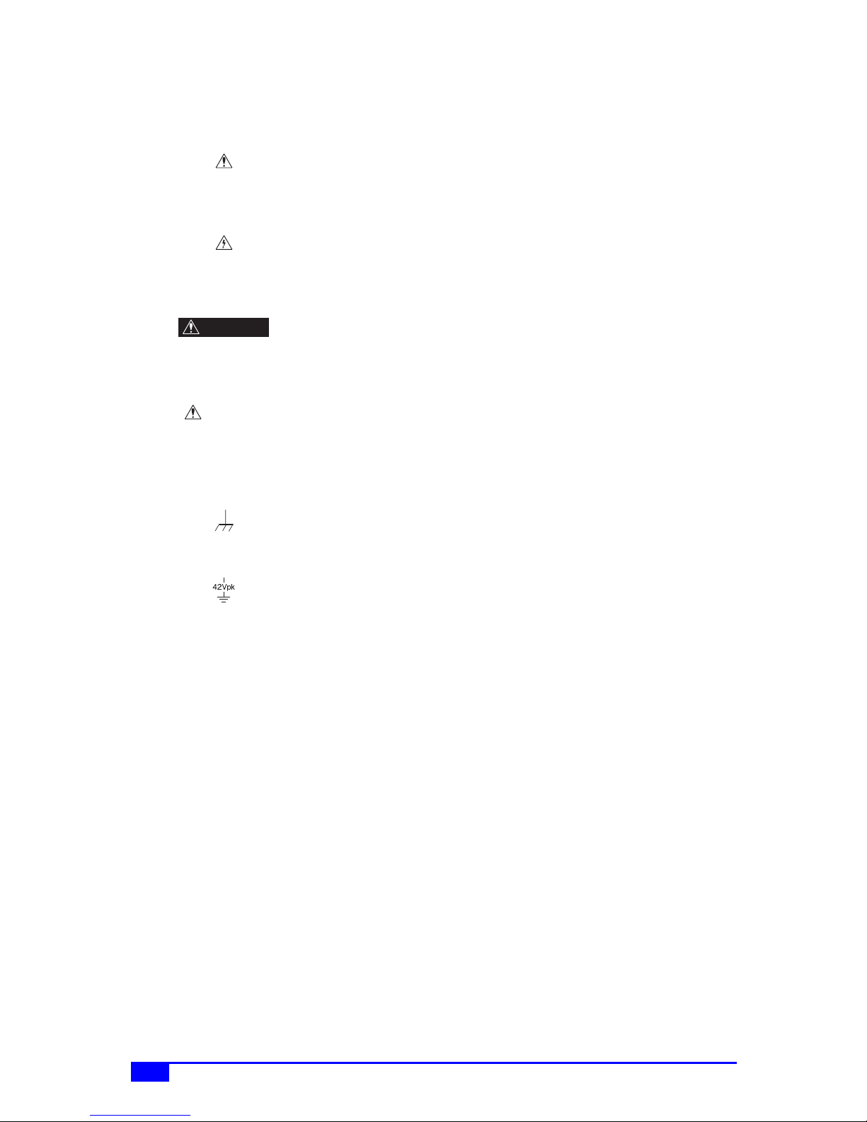
●Safety-related symbols
The general definitions of the safety-related symbols used on this product and in the
instruction manual are provided below.
Instruction Manual Reference Symbol
This symbol is displayed to alert the user to potential danger and refer
him/her to the instruction manual.
Electric Shock Danger Symbol
This symbol indicates locations that present a risk of electric shock under
specific conditions.
Warning Symbol
This symbol indicates information for avoiding danger to human life or
bodily injury while handling this product.
Caution Symbol
This symbol indicates information for preventing damage to the product
when handling it.
●Other symbols
This symbol indicates that the external conductor of the connector is
connected to the case.
This symbol shows that the external conductor of the connector is
insulated from the case.
It shows, however, that the potential difference from the grounding
potential is restricted to 42 Vpk or lower for safety. (Since this product is
grounded when used, the potential of the case equals the grounding
potential.)
●Waste disposal
To help ensure environmental protection, use a professional industrial waste contractor to
dispose of this product. A battery is not used for this product.
WARNING
CAUTION

V
WF1973/WF1974
Contents
Preface .................................................................................................................I
Safety Precautions..............................................................................................III
Contents ............................................................................................................. V
Figures and Tables .......................................................................................... VIII
1. OVERVIEW ....................................................................................................1
1.1 Features............................................................................................................. 1
1.2 Operating Principles .......................................................................................... 2
2. PREPARATIONS BEFORE USE ...................................................................4
2.1 Checking Before Use......................................................................................... 4
2.2 Installation.......................................................................................................... 5
2.3 Grounding and Power Supply Connection......................................................... 6
2.4 Calibration.......................................................................................................... 7
3. PANELS AND I/O TERMINALS......................................................................8
3.1 Panel Components and Operations................................................................... 8
3.1.1 Front panel of WF1973 .............................................................................. 8
3.1.2 Rear panel of WF1973............................................................................... 9
3.1.3 Front panel of WF1974 ............................................................................ 10
3.1.4 Rear panel of WF1974............................................................................. 11
3.2 I/O Terminals ................................................................................................... 12
3.2.1 Waveform output (FCTN OUT) ................................................................ 12
3.2.2 Sync/sub-output (SYNC/SUB OUT)......................................................... 13
3.2.3 External modulation/addition input (MOD/ADD IN) .................................. 14
3.2.4 External trigger input (TRIG IN) ............................................................... 14
3.2.5 External 10 MHz frequency reference input (10 MHz REF IN) ................ 15
3.2.6 Frequency reference output (REF OUT).................................................. 16
3.2.7 Multi-I/O (MULTI I/O)................................................................................ 16
3.3 Cautions on Floating Ground Connection........................................................ 19
4. BASIC OPERATION.....................................................................................21
4.1 Power on/off Switching and Restoration of Settings........................................ 21
4.1.1 Power on/off switching method ................................................................ 21
4.1.2 Restoration of settings at power-on ......................................................... 22
4.2 Screen Configuration and Operation .............................................................. 25
4.2.1 Screen configuration ................................................................................ 25
4.2.2 Switching display format with tabs (displaying waveform graph) ............. 27
4.2.3 Top menu ................................................................................................. 29
4.3 Basic Settings and Operations ........................................................................ 30

VI MULTIFUNCTION GENERATOR
4.3.1 Changing the frequency, amplitude, and other values............................. 30
4.3.2 Changing the waveform and oscillation mode ......................................... 33
4.3.3 Manipulating shortcut keys for changing basic parameters ..................... 34
4.3.4 Operations of ENTER key, CANCEL key, and UNDO key ..................... 35
4.3.5 Changing the display unit......................................................................... 36
4.3.6 CH1/CH2 switching key and active channel (WF1974 only).................... 38
4.3.7 Actions possible in the Utility screen........................................................ 39
4.3.8 Restoring the initial settings ..................................................................... 41
4.3.9 Output on/off ............................................................................................ 41
4.4 Setting Methods for Main Items....................................................................... 43
4.4.1 Configuration of text display screen in continuous oscillation mode ........ 43
4.4.2 Setting the oscillation mode ..................................................................... 43
4.4.3 Setting the waveform ............................................................................... 44
4.4.4 Setting the frequency ............................................................................... 44
4.4.5 Performing setting with period.................................................................. 45
4.4.6 Setting the phase ..................................................................................... 45
4.4.7 Setting the amplitude ............................................................................... 48
4.4.8 Setting DC offset ...................................................................................... 50
4.4.9 Setting the output level with high level/low level ...................................... 51
4.4.10 Setting the waveform polarity and amplitude range............................... 52
4.4.11 How to use auto range/range hold for the output voltage ...................... 54
4.4.12 Setting the load impedance.................................................................... 55
4.4.13 Adding external signal............................................................................ 57
4.4.14 Setting the square wave duty................................................................. 59
4.4.15 Setting the pulse width and leading/trailing edge time of a pulse wave . 61
4.4.16 Setting the ramp wave symmetry........................................................... 64
4.5 Using Parameter-Variable Waveforms ............................................................ 65
4.6 Using Arbitrary Waveforms.............................................................................. 67
4.7 Modulation Setting and Manipulation............................................................... 69
4.7.1 Modulation types ...................................................................................... 69
4.7.2 Screen for modulation setting and manipulation ...................................... 70
4.7.3 Common modulation settings and manipulations .................................... 72
4.7.4 Setting FM................................................................................................ 75
4.7.5 Setting FSK .............................................................................................. 76
4.7.6 Setting PM................................................................................................ 77
4.7.7 Setting PSK.............................................................................................. 78
4.7.8 Setting AM................................................................................................ 79
4.7.9 Setting AM (DSB-SC)............................................................................... 80
4.7.10 Setting DC offset modulation ................................................................. 81
4.7.11 Setting PWM .......................................................................................... 82
4.8 Sweep Setting and Manipulation ..................................................................... 83
4.8.1 Sweep types............................................................................................. 83
4.8.2 Screen for sweep setting and manipulation ............................................. 83

VII
WF1973/WF1974
4.8.3 Common sweep settings and manipulations............................................ 86
4.8.4 Setting frequency sweep.......................................................................... 95
4.8.5 Setting phase sweep................................................................................ 97
4.8.6 Setting amplitude sweep .......................................................................... 99
4.8.7 Setting DC offset sweep......................................................................... 101
4.8.8 Setting duty sweep................................................................................. 103
4.9 Burst Setting and Manipulation...................................................................... 105
4.9.1 Burst oscillation types ............................................................................ 105
4.9.2 Auto burst............................................................................................... 106
4.9.3 Trigger burst........................................................................................... 109
4.9.4 Gate oscillation....................................................................................... 113
4.9.5 Triggered gate oscillation....................................................................... 118
5. SAVING AND RECALLING SETTINGS .....................................................122
5.1 Saving Settings.............................................................................................. 122
5.2 Recalling Settings .......................................................................................... 124
6. LIST OF INITIAL SETTINGS ......................................................................126
7. SPECIFICATIONS......................................................................................129
7.1 Oscillation Modes .......................................................................................... 129
7.2 Waveforms..................................................................................................... 129
7.2.1 Standard waveforms .............................................................................. 129
7.2.2 Arbitrary waveforms ............................................................................... 129
7.3 Frequency, Phase.......................................................................................... 130
7.4 Output Characteristics ................................................................................... 130
7.4.1 Amplitude ............................................................................................... 130
7.4.2 DC offset ................................................................................................ 130
7.4.3 Load impedance setting......................................................................... 131
7.4.4 Waveform output.................................................................................... 131
7.4.5 Sync/sub output ..................................................................................... 131
7.5 Signal Characteristics .................................................................................... 131
7.5.1 Sine wave............................................................................................... 131
7.5.2 Square wave .......................................................................................... 132
7.5.3 Pulse wave............................................................................................. 132
7.5.4 Ramp wave ............................................................................................ 133
7.5.5 Parameter-variable waveforms .............................................................. 133
7.6 Modulated Oscillation Mode .......................................................................... 136
7.6.1 General .................................................................................................. 136
7.6.2 Modulation conditions ............................................................................ 137
7.7 Sweep Oscillation Mode ................................................................................ 138
7.7.1 General .................................................................................................. 138
7.7.2 Sweep conditions ................................................................................... 139

VIII MULTIFUNCTION GENERATOR
7.8 Burst Oscillation Mode................................................................................... 139
7.9 Triggers.......................................................................................................... 140
7.10 Sequence..................................................................................................... 141
7.11 Other I/Os .................................................................................................... 142
7.12 2-channel ganged operation (WF1974 only) ............................................... 143
7.13 Synchronous Operation of Multiple Units .................................................... 144
7.14 User-Defined Units ...................................................................................... 144
7.15 Other Functions ........................................................................................... 145
7.16 Options ........................................................................................................ 145
7.17 General Characteristics ............................................................................... 145
■External dimensions (WF1973) ......................................................................... 147
■External dimensions (WF1974) ......................................................................... 148
RACK MOUNTING DIMENSIONS ..................................................................149
■Inch rack mounting dimensions (for 1 unit)........................................................ 149
■Inch rack mounting dimensions (for 2 units) ...................................................... 150
■Millimeter rack mounting dimensions (for 1 unit) ............................................... 151
■Millimeter rack mounting dimensions (for 2 units).............................................. 152
Index ................................................................................................................153
WARRANTY ....................................................................................................157
Figures and Tables
Figure 3-1. Front Panel of WF1973............................................................................ 8
Figure 3-2. Rear Panel of WF1973 ............................................................................ 9
Figure 3-3. Front Panel of WF1974.......................................................................... 10
Figure 3-4. Rear Panel of WF1974 .......................................................................... 11
Figure 3-5. Multi-I/O Connector Pin Assignment...................................................... 17
Figure 3-6. Cautions on Floating Ground Connection for WF1973 .......................... 20
Figure 3-7. Cautions on Floating Ground Connection for WF1974 .......................... 20
Table 3-1. Signals Selectable for Sync/Sub-Output ................................................. 13
Table 3-2. Multi-I/O Connector Function Allocation.................................................. 18

1
WF1973/WF1974
1. OVERVIEW
1.1 Features
The WF1973 and WF1974 are multifunctional generators based on direct digital synthesizers
(DDS).
The WF1973 is a 1-channel generator, while the WF1974 is a two-channel generator.
• Highest frequency: 30 MHz (sine wave), 15 MHz (square wave, pulse)
• Frequency accuracy: ±(3 ppm + 2 pHz), high resolution of 0.01 µHz. 10 MHz external
frequency reference can be used.
• Maximum output voltage: 20 Vp-p/open, 10 Vp-p/50 Ω
• Large number of standard parameter-variable waveforms: Sine wave, square wave
(variable duty), pulse (variable pulse width/duty, leading edge time, trailing edge time),
ramp wave (variable symmetry), CF controlled sine wave (variable crest factor), staircase
sine wave (variable number of steps), Gaussian pulse (variable σ), Sin(x)/x (variable
number of zero crossings), exponential rise/fall (variable time constant), damped
oscillation (variable oscillation frequency, damping time constant), pulse surge (variable
rising and duration times), trapezoid (variable rise, fall, and upper base width), and so on.
• Large-capacity arbitrary waveform memory: 512 K words max., saving capacity: 128
waveforms/4 M words
• Phase and waveform remain continuous even when frequency is changed or during
frequency sweep.
• Square wave, pulse with variable duty and high resolution of 0.0001%
• Pulse with variable leading edge time and trailing edge time
• Various oscillation modes
• Continuous oscillation
• Modulation: FM, FSK, PM, PSK, AM, DC offset modulation, PWM
• Sweep: Frequency, phase, amplitude, DC offset, duty
• Burst oscillation: Auto burst, trigger burst, gate oscillation, triggered gate oscillation
• Sequence oscillation: Variable waveform/ frequency/ phase/ amplitude/ DC offset/
square wave duty, constant value/ linear interpolation, jump/ repeat/ hold/ branch
• Sequence function for easy test waveform creation and adjustment
Flexible waveform creation possible through combination with standard parameter-
variable waveforms
Frequency, phase, amplitude, etc., can be rapidly changed and swept
• Intuitive user interface through use of high-resolution QVGA TFT color LCD
• Two-channel ganged function with 2 phases, constant frequency difference, constant
frequency ratio, and differential output (only WF1974)
• Floated from housing for each channel to reduce effect of ground loop
• Multiple-phase oscillator can be configured by synchronizing multiple units
• USB and GPIB interfaces provided
• Thin and lightweight: Height of approx. 9 cm, weight of approx. 2.1 kg

2
1. OVERVIEW
MULTIFUNCTION GENERATOR
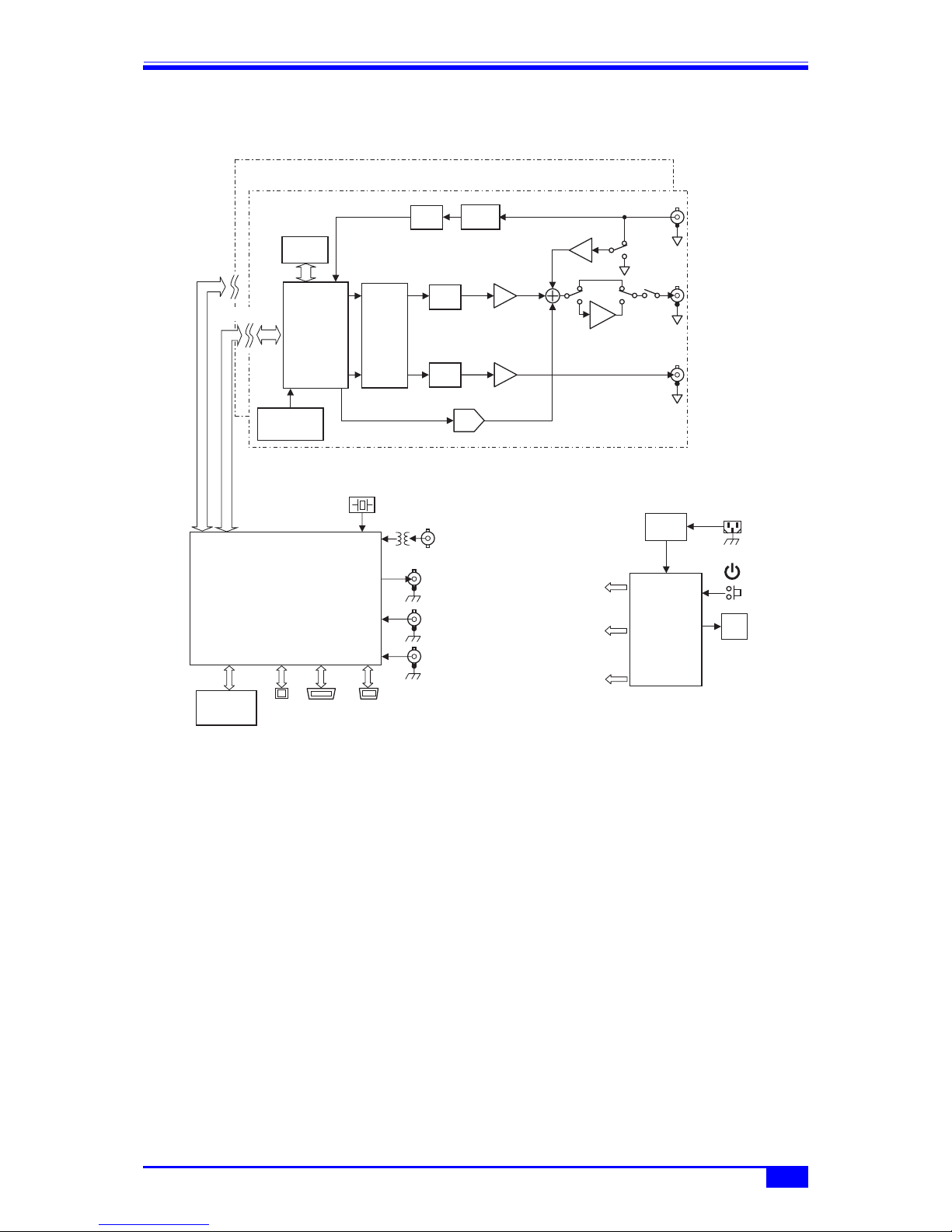
1.2 Operating Principles
■WF1973 block diagram
■Analog block
• The DDS (digital direct synthesizer) uses a 120 MHz clock to generate various types of
oscillation and waveforms. Modulation, sweep, burst, and sequence are also processed
within the DDS.
• The digital waveforms generated by the DDS are controlled to the specified polarity
(normal, inversed) in the amplitude range (−FS/0, ±FS, 0/+FS), and following digital
amplitude adjustment, the signal is input into the digital to analog (D/A) converter.
• The waveform converted into an analog signal by the D/A is then smoothed by the lowpass
filter (LFP), and the amplitude is controlled in 10 dB steps by the programmable gain
amplifier (PGA).
• The external addition signal and DC offset are added to the PGA output. When an output
voltage exceeding ±2V/open is required, output is done via the ×5 amplifier.
• The maximum output voltage of the product is either 20 Vp-p or 4 Vp-p depending on
whether or not the ×5 amplifier is used. Also depending on this, the external addition gain
is either ×10 or ×2.
• After passing through the LPF, the external modulation signal undergoes A/D conversion
and is then input to the DDS.
ANALOG
REF OUT
TRIG IN
10MHz REF IN
for ANALOG
+12V
100V...230V
㨪LINE
MOD/ADD
IN
FCTN
OUT
SYNC/SUB
OUT
A/D LPF
LPF
D/A
DC OFFSET
120MHz
r10Vmax
PGA
0/-10/-20/-30dB
LPF
r1V
2
TTL/r3V
5
r2Vmax
EXTERNAL
MODULATION
EXTERNAL
ADDITION
ISOLATION
DDS
WAV E
MEMORY
16bit
512Kw
16bit-
2CH
D/A
CLOCK
GENERATOR
20MHz
SYSTEM
CONTROLLER
MULTI
I/O
GPIBUSB
FRONT
PA N E L
UNIT
AC/DC
POWER
SUPPLY
FA N
for SYSTEM
CONTROLLER
1.2 Operating Principles
3
WF1973/WF1974
■WF1974 block diagram
• The analog block is insulated from the system controller block located in the housing
potential.
• In the WF1974, the analog block comprises two channels, each individually isolated from
the housing potential.
■System controller block
• This block performs control of the analog block, including the display, panel key
processing, remote control (GPIB, USB) processing, trigger input processing, frequency
reference control, DDS control, amplitude, and DC offset.
• A 20 MHz crystal oscillator is used as the basic oscillation of the DDS.
• The signal to synchronize multiple units is sent to REF OUT (frequency reference output),
and the inter-channel sync (WF1974 only) is sent to the analog block of each channel.
■Power supply block
• The AC/DC directly connected to the power supply input is in a constantly powered state.
• Control of each power supply circuit is done through power switch manipulation.
ANALOG CH1
AC/DC
FA N
for ANALOG CH1
+12V
㨪LINE
100V...230V
for ANALOG CH2
REF OUT
TRIG IN CH1
10MHz REF IN
TRIG IN CH2
ANALOG CH2
MOD/ADD
IN
FCTN
OUT
SYNC/SUB
OUT
A/D LPF
LPF
DDS
D/A
DC OFFSET
16bit
512Kw
WAV E
MEMORY
120MHz
r10Vmax
PGA
0/-10/-20/-30dB
LPF
r1V
2
TTL/r3V
5
r2Vmax
EXTERNAL
MODULATION
EXTERNAL
ADDITION
ISOLATION
POWER
SUPPLY
for SYSTEM
CONTROLLER
20MHz
SYSTEM
CONTROLLER
MULTI
I/O
GPIBUSB
FRONT
PA N E L
UNIT
16bit-
2CH
D/A
CLOCK
GENERATOR

4MULTIFUNCTION GENERATOR
2. PREPARATIONS BEFORE USE
2.1 Checking Before Use
a) Safety check
To ensure safety in using the WF1973/WF1974, the user should read the following sections
of this instruction manual before using the WF1973/WF1974:
•Safety Precautions (provided at the beginning of this instruction manual)
• 2.3 Grounding and Power Supply Connection
b) Appearance and accessories check
If an abnormality (such as a flaw or dent) is found on the outside surface of the corrugated
box, carefully check if the product is adversely affected when removing the product from the
corrugated box.
After opening the corrugated box, check the items contained in the box.
If an abnormality such as a flaw or dent is found on the product, or an accessory is missing,
contact NF Corporation or its representative.
• Appearance check
Check that no abnormalities such as a flaw and dent are found on the panel, controls,
connectors, and so forth.
• Configuration and accessory check
The accessories of this product are listed below. Check that there are no missing items
and no flaws are found.
WARNING
This product contains high-voltage parts. Never remove the cover.
All internal inspections of this product are to be performed only by service
technicians qualified by NF Corporation.
Main unit................................................................................................................. 1
Instruction Manual (Basics)................................................................................... 1
CD (PDF instruction manuals, application software) .......................................... 1
PDF instruction manuals:
Basics, Application, Remote Control,
Arbitrary Waveform Editing Software, Sequence Editing Software,
LabVIEW Driver
Application software:
Arbitrary Waveform Editing Software, Sequence Editing Software,
LabVIEW Driver
Power cord set (2 m, with 3-prong plug)................................................................ 1

2.2 Installation
5
WF1973/WF1974
c) Repacking
When repacking this equipment for transportation, etc., use a shipping carton of sufficient
strength and capacity to safely accommodate the equipment and hold its weight.
d) Options
The following options are available and can be purchased separately.
• Multi-I/O cable (PA-001-1318)
This cable is used when using the multi-I/O connector on the rear panel.
A 2 meter multi-core shielded cable is connected to the mini-Dsub 15-pin connector. Since
the opposite side is cut off, process that side according to the connection destination.
For the connector's pin assignment and cable differentiation, )p. 18.
• Rack mount adapters
These adapters are for mounting the equipment on a 19-inch IEC, EIA standard rack, or
JIS standard rack.
Each type of adapter is available as a 1-unit and 2-unit model (for side-by-side mounting),
for a total lineup of 4 models.
2.2 Installation
a) Installation sites
Do not place the equipment with the rear panel facing down, because this may damage the
connectors and hinder ventilation.
Place the equipment on a flat surface such as a desk so that the four rubber feet and stands
on the bottom side rest on that surface.
b) Installation location conditions
• This product uses a fan for forced-air cooling and features air intake and exhaust vents on the
side and rear panels for this purpose. To allow for ample air flow, be sure to maintain a gap of
at least 10 cm between the sides and rear of this product and walls or other obstructions.
• Install this product in a location that meets the following conditions for temperature and
humidity ranges.
Operating conditions: 0 to 40ºC, 5 to 85%RH
Storage conditions: −10 to 50ºC, 5 to 95%RH
Further, a condensation-free environment must be ensured. For limitations related to
absolute humidity, refer to the specifications in this manual.
• Do not install the WF1973/WF1974 in the following locations:
• Location with flammable gas
An explosion may occur. Never install and use this product in such a location.
• Outdoors, or location exposed to direct sunlight or near a fire or heat source
The full performance of this product may not be obtained, or failure may occur.
• Location with corrosive gas, moisture, dust, or high humidity
This product may become corroded or fail.
• Location near an electromagnetic field source, high-voltage device, or power line
This product may malfunction.
• Location exposed to excessive vibration
This product may malfunction or fail.

6
2. PREPARATIONS BEFORE USE
MULTIFUNCTION GENERATOR
c) Panel and case cleaning
Use a soft cloth to wipe dust from the panel and case. If soiling is severe, moisten the cloth
with a neutral detergent and wring it out well.
Do not use volatile substances such as thinners and benzene, or commercial wipes, as these
may deform or peel the finish.
d) Rack mounting method
When provided with a rack mount adapter (option), this equipment can be mounted on a 19-
inch IEC, EIA standard rack, or JIS standard rack. Either one unit, or two side-by-side
units, can be mounted.
First, attach the rack mount adapter to the main unit, and then mount the main unit into
the rack. For the rack mount adapter handling method, refer to the manual included with
the adapter.
When rack mounting the main unit, observe the following cautions.
• Be sure to install rails in the rack to support the equipment.
• Mounting the equipment into a fully enclosed rack may cause it to fail due to rising
temperature.
Be sure to provide sufficient ventilation openings and forcibly cool the inside of the rack
with fans.
For external dimensions for rack mounting, refer to:
Inch rack mounting dimensions (for 1 unit) )p. 149
Inch rack mounting dimensions (for 2 units) )p. 150
Millimeter rack mounting dimensions (for 1 unit) )p. 151
Millimeter rack mounting dimensions (for 2 units) )p. 152
2.3 Grounding and Power Supply Connection
a) Grounding
Be sure to ground the equipment.
WARNING
This product uses a line filter. Be sure to ground this product. Otherwise, an
electric shock may occur.
To prevent electric shock, be sure to safely implement grounding such that
ground resistance is 100 Ωor lower.
When a 3-prong power plug that includes a protective ground contact is connected to a 3-
prong power supply outlet, this product is grounded automatically.
This product does not come with a 3-prong to 2-prong conversion adapter. When using a
separately sold 3-prong to 2-prong conversion adapter, be sure to connect the grounding
wire of the adapter to the grounding terminal next to the outlet.
b) Power supply conditions
Voltage range: 100 V AC to 230 V AC ±10% (250 V or lower)
Frequency range: 50 Hz/60 Hz
Power consumption: WF1973: 50 VA or lower; WF1974: 75 VA or lower

2.4 Calibration
7
WF1973/WF1974
c) Power supply connection procedure
1)Check that the commercial power supply voltage to be connected is within the voltage
range specified for the equipment.
2)Connect the power cord to the power supply inlet on the rear panel of the equipment.
3)Connect the power cord plug to the 3-prong power supply outlet.
The withstand voltage of the main unit proper is 1500 Vrms (AC).
CAUTION
The power cord supplied with this equipment is designed to be used for this
equipment only. Do not use this power cord for other equipment or purposes.
2.4 Calibration
This equipment should undergo performance testing about once a year as a guideline,
although this depends on the usage environment and usage frequency. Moreover, when using
this equipment to perform important measurements and tests, the execution of a performance
test immediately before is recommended.
Performance testing of this equipment should be performed by a person with general
knowledge of test instruments and experienced in their operation.
For details on performance tests, )“10. MAINTENANCE” in the Application Instruction
Manual.

8MULTIFUNCTION GENERATOR
3. PANELS AND I/O TERMINALS
3.1 Panel Components and Operations
This section describes the names and functions of the various components on the front and
rear panels.
Figure 3-1. Fro nt Panel of WF1973
3.1.1 Front panel of WF1973
Figure 3-1. Front Panel of WF1973
Numeric keypad
Used for numerical input
)p. 31
Basic parameter
shortcut keys
Press to allow the waveform,
frequency, amplitude, and DC
offset to be changed
)p. 34
MENU key
Displays the top menu
)p. 29
Manual trigger key
Used for sweep, burst trigger
)pp. 90, 111, 115, 120
Triggered lamp
Lights when a trigger is accepted
)pp. 90, 111, 115, 120
LCD panel
Power switch
)p. 21
NEXT key
Press to switch setting
screen pages.
)p. 26
UNDO key
Press to undo setting changes.
)p. 35
CANCEL key
Press to cancel.
)p. 35
ENTER key
Press to enter a setting.
)p. 35
Arrow keys
Press to select items, or increase/
decrease values.
)p. 30
Modify knob
Press to select items, or increase/
decrease values.
)p. 30
External modulation/addition input terminal
)p. 14
Sync/sub-output terminal )p. 13
External trigger input terminal )p. 14
Waveform output on/off key
Press to switch waveform output on/off.
When on, the lamp on the left is lit.
)p. 41
Waveform output terminal )p. 12
Soft keys
The manipulation
parameter is displayed on
the LCD panel.
)p. 26

3.1 Panel Components and Operations
9
WF1973/WF1974
Figure 3-2. R ear Panel of WF1973
3.1.2 Rear panel of WF1973
Figure 3-2. Rear Panel of WF1973
GPIB connector
Exhaust vent
)p. 5
Power supply input
)p. 6
Multi-I/O connector
Used for sweep, sequence control,
sync code output
)p. 16
Frequency reference output terminal
)p. 16
External 10 MHz frequency reference input
terminal
)p. 15
USB connector

10
3. PANELS AND I/O TERMINALS
MULTIFUNCTION GENERATOR
Figure 3-3. Fro nt Panel of WF1974
3.1.3 Front panel of WF1974
Figure 3-3. Front Panel of WF1974
CH2 sync/sub-output terminal
)p. 13
CH2 waveform output on/off key
Press to switch CH2 waveform output on/off.
When off, the lamp on the left is lit.
)p. 41
CH2 waveform output terminal
)p. 12
CH1 sync/sub-output terminal
)p. 13
CH1 waveform output on/off key
Press to switch CH1 waveform output on/off.
When on, the lamp on the left is lit.
)p. 41
CH1 waveform output terminal
)p. 12
CH1/CH2 switching key
Press to switch the channel
to be set on the LCD panel.
)p. 38
UNDO key
Press to undo setting changes
)p. 35
CANCEL key
Press to cancel.
)p. 35
ENTER key
Press to enter a setting
)p. 35
Arrow keys
Press to select items, or
increase/decrease values
)p. 30
Modify knob
Press to select items, or
increase/decrease values
)p. 30
Numeric keypad
Used for numerical input
)p. 31
Basic parameter
shortcut keys
Press to allow the waveform,
frequency, amplitude, and DC
offset to be changed
)p. 34
MENU key
Displays the top menu
)p. 29
Power switch
)p. 21
NEXT key
Press to switch setting
screen pages.
)p. 26
Soft keys
The manipulation
parameter is displayed on
the LCD panel.
)p. 26
LCD panel
Manual trigger key
Used for sweep, burst trigger
)pp. 90, 111, 115, 120
Triggered lamp
Lights when a trigger is accepted
)pp. 90, 111, 115, 120
Other manuals for WF1973
1
This manual suits for next models
1
Table of contents
Other NF Inverter manuals


Popular Inverter manuals by other brands

Danfoss
Danfoss Holip HLP-C+ Series instructions

Mecc Alte
Mecc Alte ECO-ECP 4 Operating and maintenance instructions

SOLIS
SOLIS S6 Series user manual

Pyramid
Pyramid 5 KW 3 Phase User & installation manual

GE
GE VAT20 instruction manual

Trane
Trane CGA-SVX01A-EN Installation, operation and maintenance manual


