Pyramid 5 KW 3 Phase Guide
An ISO 9001 Certified Company
THREE PHASE GRID TIED
SOLAR INVERTER
User & Installation Manual for 5 KW 3 Phase Solar
Inverter to be connected to the Utility Grid in India
2021

5KW 3-Phase Grid Tied Solar Inverter 1
Contents
1 Introduction 3
1.1 Overview ........................................... 3
1.2 Factors Affecting The Performance of Inverter .................. 3
1.2.1 Rating for PV modules ............................. 3
1.2.2 Temperature and Power Reduction: ..................... 3
1.2.3 Angle of the Sun .................................. 4
1.2.4 Partial Shade .................................... 4
1.2.5 Other Factors .................................... 4
2 Important Safety Warning 4
2.1 General Precautions ................................... 4
3 Unpacking & Overview 6
3.1 Packing List ......................................... 6
3.2 Product Overview ..................................... 6
4 Installation Procedure 7
4.1 Selection of Mounting Location ............................ 7
4.2 Mounting Solar Inverter on Wall Mounting Bracket ............... 7
5 Grid, PV and Antennas Connection 9
5.1 Grid (AC) Connection .................................. 9
5.1.1 Preparation ..................................... 9
5.1.2 Connection to AC Utility ............................ 9
5.2 Solar (DC) Connection .................................. 12
5.2.1 PV Terminal Connections ............................ 12
5.3 GSM / WiFi Connection ................................ 16
6 Turning the Inverter ON 17
7 Remote Monitoring for Users 17
7.1 Configuring GSM/WiFi Module of Solar Inverter ................. 17
7.2 Remote Monitoring Using Web App ......................... 19
7.3 Remote Monitoring Using Mobile App ....................... 25
8 Maintenance and Cleaning 32
9 Trouble Shooting 33
9.1 Fault Related Information ................................ 33
10 User Interface 34
10.1 Checking Solar Energy Data . . . . . . . . . . . . . . . . . . . . . . . . . . . . . . . . . 34
10.2SettingUpInverterModes.................................. 36
10.3SettingUpRestartTimer .................................. 37
11 Technical Data 38
©
Pyramid Electronics

5KW 3-Phase Grid Tied Solar Inverter 2
USER MANUAL
5 KW THREE PHASE
GRID-TIED SOLAR INVERTER
©
Pyramid Electronics

5KW 3-Phase Grid Tied Solar Inverter 3
1 Introduction
1.1 Overview
This solar inverter is a power conditioning equipment that converts DC solar electric (photovolatic
or PV) power into ac utility-grade electricity that can be sold to local power company. The inverter
performs Maximum Power Point Tracking (MPPT) and extracts out the maximum power possible
from the solar PV string connected at its input.
Figure 1: A typical roof-top solar PV system
This inverter can only be used with a solar PV string (PV modules connected in series) with open
circuit dc voltage less than 1000 V DC. This inverter CANNOT be used with any other regular dc
voltage source. Note that the present inverter uses zero residual current transformerless topology due
to which any sort of PV modules (Mono-crystalline PV, Poly-Crystalline PV, thin film PV) can be
connected to the inverter. A typical roof-top solar PV system is shown in Figure 1 on page 3. In
Distribution Box, typically a separate DC circuit breaker is installed between inverter and PV string
and a separate AC circuit breaker is typically installed between inverter and grid utility.
1.2 Factors Affecting The Performance of Inverter
There are a lot of factors that can influence the performance of this inverter.
1.2.1 Rating for PV modules
PV modules are rated at ideal factory conditions, such as specified illumination (1000 W/m2), spec-
trum of light and temperature (25 0C/ 77 0F). This is called the STC (Standard Test Condition)
rating and is the figure that appears on the specification label of PV module. Generally speaking,
only around 60% to 70% of its peak STC-rated output will be produced from the PV modules due to
unpredicted environmental factors.
1.2.2 Temperature and Power Reduction:
Environment temperature affects the power output of PV modules. Higher the temperature, lower
the power output of PV module. Comparing the pole-mounted PV array, roof-mounted PV module
array generates less power due to less air circulation and and excessive heat from the roof top.
©
Pyramid Electronics
5KW 3-Phase Grid Tied Solar Inverter 4
1.2.3 Angle of the Sun
The array orientation can dramatically affect the PV array output. The array energy output will vary
depending on the time of day and time of year as the sun’s angle in relation to the array changes.
Sunlight output decreases as the sun approaches the horizons (such as in winter in Europe) due to
the greater atmospheric air mass it must penetrate, reducing both the light intensity that strikes the
array’s surface and spectrum of the light. In general, one can expect only four to six hours of direct
sunlight per day depending on what part of the world the inverter is installed.
1.2.4 Partial Shade
Shading on a single PV module of the array can reduce the output power. Such shading can be caused
by something as simple as the shadow of a utility wire or tree branch on part of the array’s surface.
The inverter is designed to maximize its power production in all of the above situations using the
sweep method MPPT algorithm.
1.2.5 Other Factors
Other factors that reduce power generation of a solar system are:
Dust or dirt on the modules.
Fog or smog.
Mismatched PV array modules, with slight inconsistencies in performance from one module to
another (A solar PV string consisting of solar panels with different power rating or same power
rating but different manufacturers is unacceptable).
Inverter efficiency.
Wire losses.
2 Important Safety Warning
Before using the inverter, please read all instructions and cautionary markings on the
unit and this manual. Store the manual where it can be accessed easily.
This manual is for qualified personnel. The task described in this manual may be performed by qual-
ified personnel only.
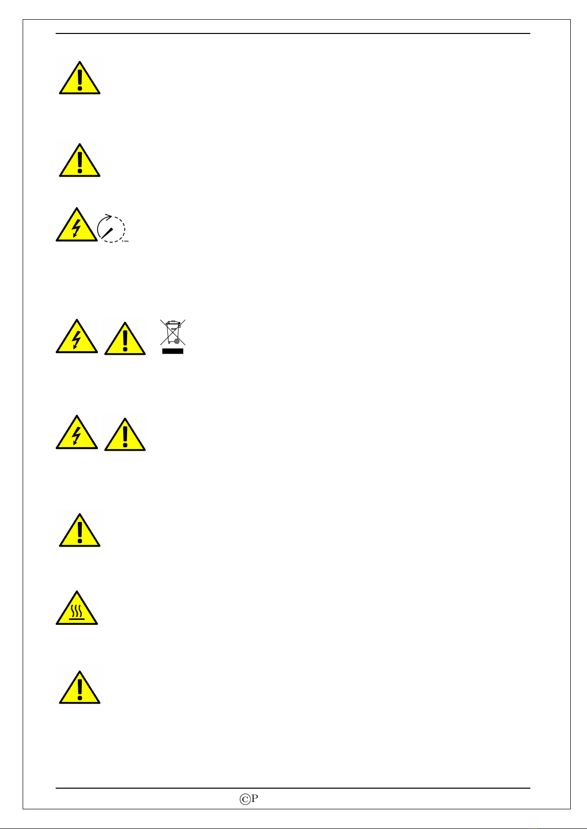
2.1 General Precautions
Convention Used:
WARNING! Warnings identify conditions or practices that could result in personal injury.
CAUTION! Caution identifies conditions or practices that could result in damaged to the unit
or other equipment connected.
WARNING! Before installing and using this inverter, read all instructions and cautionary markings
on the inverter and all appropriate sections of this guide.
©
Pyramid Electronics
5KW 3-Phase Grid Tied Solar Inverter 5
WARNING! Normally grounded conductors may be ungrounded and energized when a ground fault
is indicated.
WARNING! This inverter weighs around 16 kgs. It should be installed by at least two persons.
CAUTION! Authorized service personnel should reduce the risk of electrical shock by disconnecting
both the AC and DC power from the inverter before attempting any maintenance or cleaning or work-
ing on any circuits connected to the inverter. Turning off controls will not reduce this risk. Internal
capacitors can remain charged for 5 minutes after disconnecting all sources of power.
CAUTION! Do not disassemble and dispose off this inverter yourself. It contains no user-serviceable
parts. Attempt to service this inverter yourself may cause a risk of electrical shock or fire and will
void the warranty from the manufacturer.
CAUTION! To avoid a risk of fire and electric shock, make sure that existing wiring is in good con-
dition and that the wire is not under rated. Do not operate the Inverter with damaged or substandard
wiring.
CAUTION! Use only recommended accessories from installer. Otherwise, not-qualified tools may
cause a risk of fire, electric shock, or injury to persons.
CAUTION! To reduce risk of fire hazard, do not cover or obstruct the heat sink. When the inverter
is ON, DO NOT touch it as it can be very hot (as high as 1000C) and can cause a serious injury.
CAUTION! Do not operate the Inverter if it has received a sharp blow, been dropped, or otherwise
damaged in any way. If the Inverter is damaged, please contact the system installer.
©
Pyramid Electronics
5KW 3-Phase Grid Tied Solar Inverter 6
CAUTION! Make sure that the earth wire of the inverter is properly earthed to reduce the risk of
electric shock.
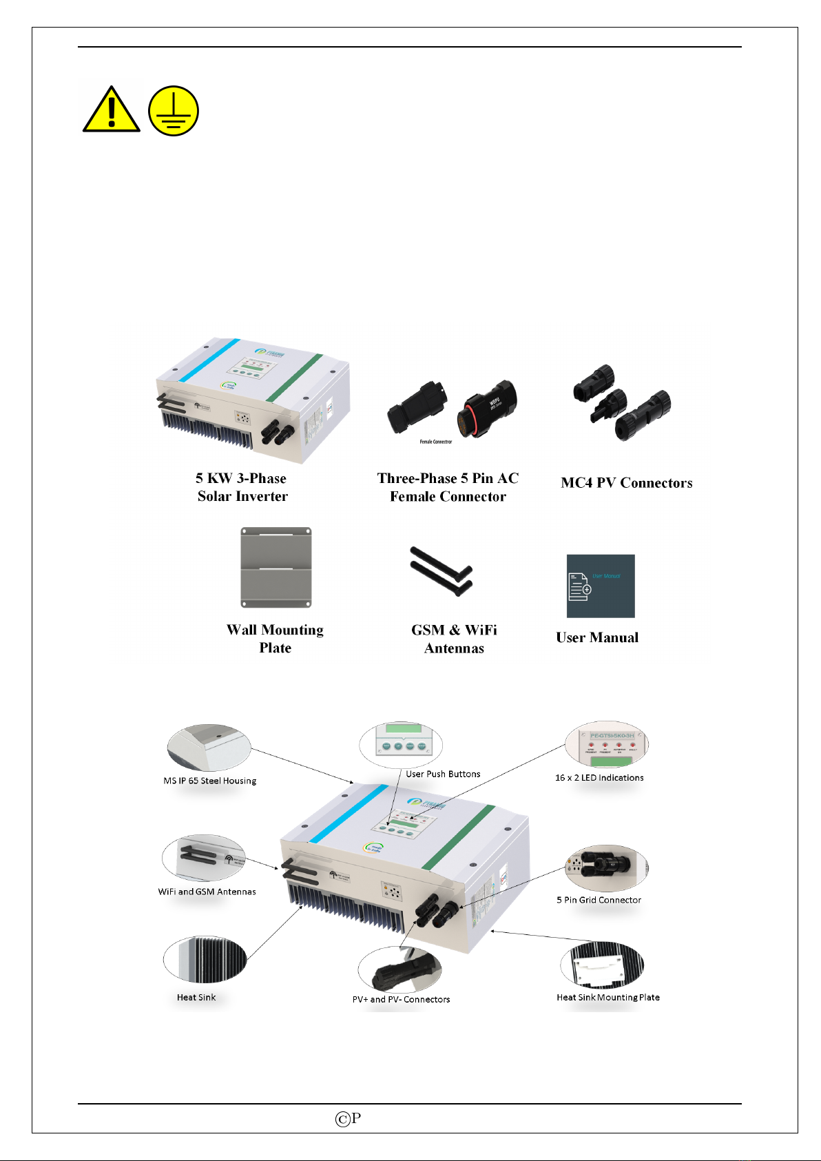
3 Unpacking & Overview
3.1 Packing List
Before installation, please inspect the unit. Be sure that nothing inside the package is damaged. The
following items must be present inside the package:
3.2 Product Overview
©
Pyramid Electronics
5KW 3-Phase Grid Tied Solar Inverter 7
4 Installation Procedure
4.1 Selection of Mounting Location
Consider the following points before selecting where to install:
Do not mount the inverter on flammable construction materials.
Mount on a solid surface.
Install this inverter at eye level in order to allow the LCD display to be read at all times.
For proper air circulation to dissipate heat, allow a clearance of atleast 20 cm to the side and
atleast 50 cm above and below the unit.
Dusty conditions on the unit may impair the performance of this inverter.
The ambient temperature should be between -25 0Cand 55 0Cto ensure optimal operation.
The recommended installation position is to be adhered to (vertical).
This inverter is designed with IP-65 for outdoor applications with high humidity.
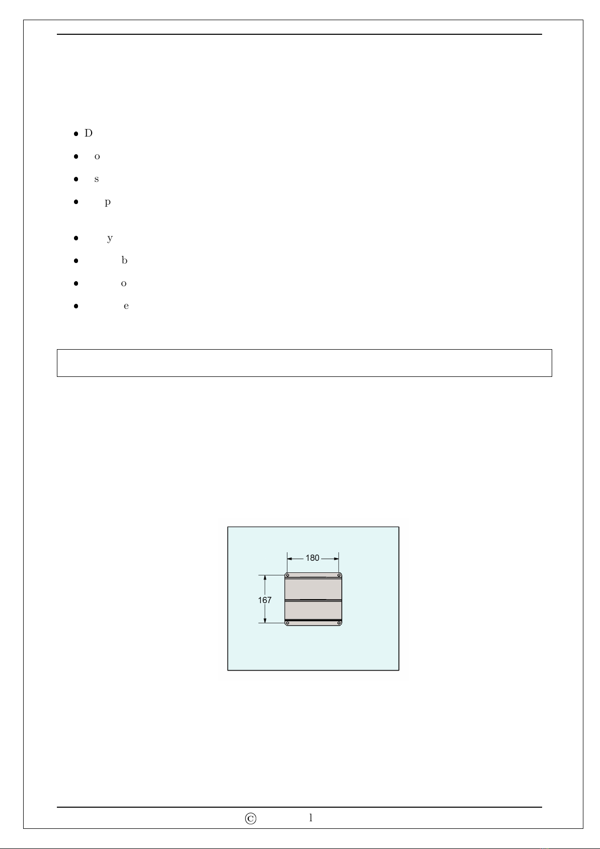
4.2 Mounting Solar Inverter on Wall Mounting Bracket
WARNING!! Remember that this inverter weighs around 16 kg! Please be careful when lifting
out from the package.
Please use the mounting plate provided in packing for problem-free installation of the solar inverter.
Installation of plate on the wall should be implemented with the proper screws. Heat sink mounting
plate has already been mounted on the inverter heat sink, user has to only mount the wall bracket so
that the solar inverter can be easily attached to the wall. After that, check that the inverter should
be bolted on wall securely. Step by step procedure is detailed next:
1. Employ the wall mounting plate as a template for marking the positions of the boreholes on the
wall.
2. Mount the wall mounting plate with appropriate screws (M5,SUS304) into four holes to fix the
mounting plate on the wall.
©
Pyramid Electronics

5KW 3-Phase Grid Tied Solar Inverter 8
3. Follow the below figure to place the solar inverter on the wall mount plate and check if the solar
inverter is firmly fixed onto the mounting plate.
4. After final fixing the solar inverter on wall mounting plate, it will look like as shown in the below
figure.
Note: If two or more solar inverters need to be installed in close proximity, then there
should be a distance of at-least 1 m between any two inverters.
©
Pyramid Electronics
5KW 3-Phase Grid Tied Solar Inverter 9
5 Grid, PV and Antennas Connection
5.1 Grid (AC) Connection
5.1.1 Preparation
Before connecting to AC utility, please install a separate AC circuit breaker between inverter and AC
utility. This will ensure the inverter can be securely disconnected under load.
Note: Although this inverter is equipped with all types of protection, it’s still necessary to install a
separate circuit breaker for safety consideration. Please use 350 V AC / 16 A circuit breaker for the
present 5 KW Three Phase Grid-Tied Solar Inverter.
Note: If one wants to add RCMU for additional safety, it shall be of type B with 30 mA leakage
current rating and 40 A nominal current rating. This RCMU can be placed between the inverter and
the grid utility.
Warning: It’s very important for system safety and efficient operation to use appropriate cable
for grid connection. To reduce risk of injury, please use the proper recommended cable size as below.
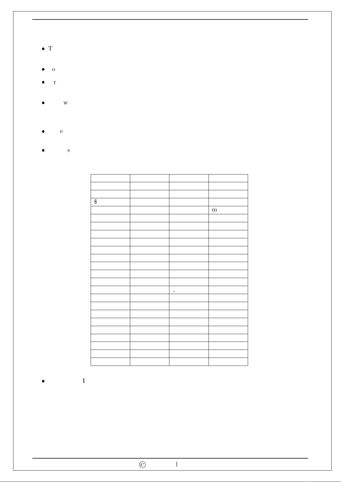
Table 1: Suggested cable requirement for grid side wire (Phase, Neutral and Earth)
Model Conductor Cross-Section
5 KW 3 Phase >= 2mm2
5.1.2 Connection to AC Utility
WARNING!! To prevent risk of electric shock, ensure the earth terminal of the solar inverter is
properly earthed before operating the solar inverter.
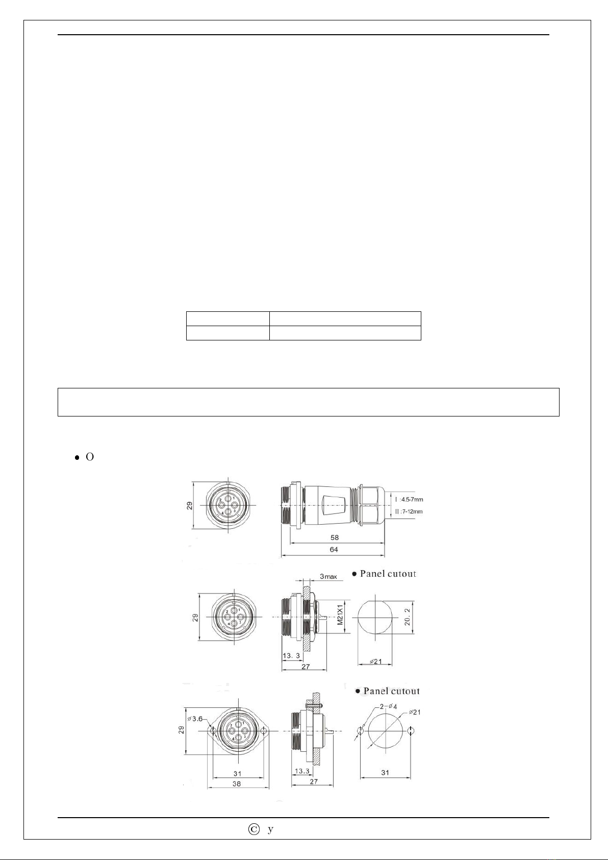
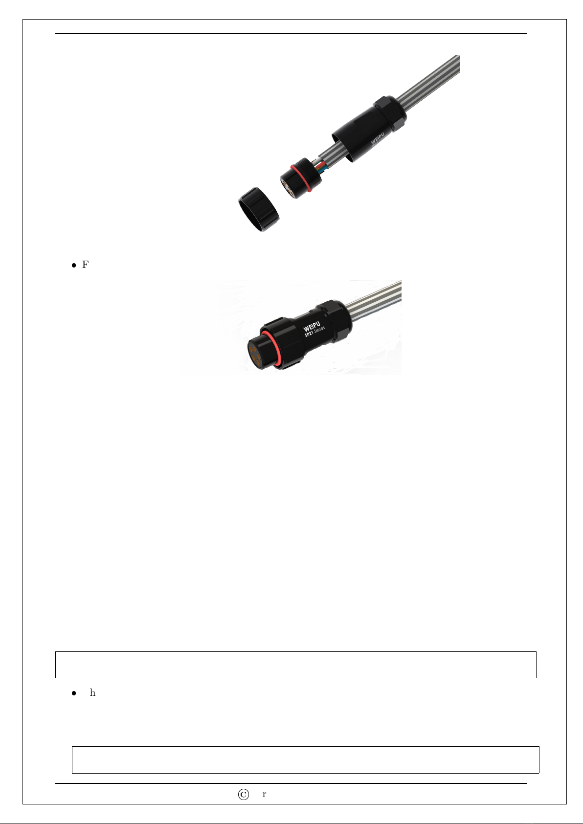
Outline size of SP21 series three-phase AC connector
Outline size of SP21 series IP68 connector.
©
Pyramid Electronics
5KW 3-Phase Grid Tied Solar Inverter 10
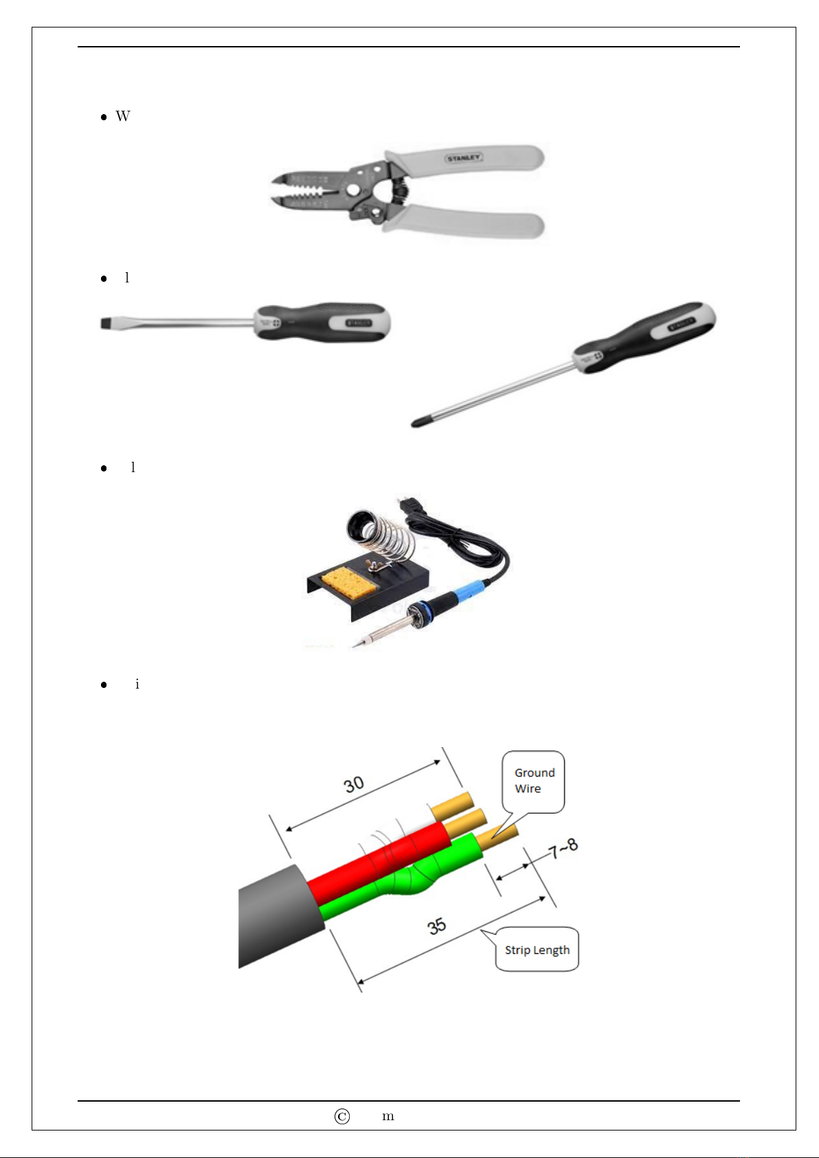
Tools used in assembly
Wire striper.
Flat screwdriver and cross screwdriver.
Soldering iron used to solder the wires.
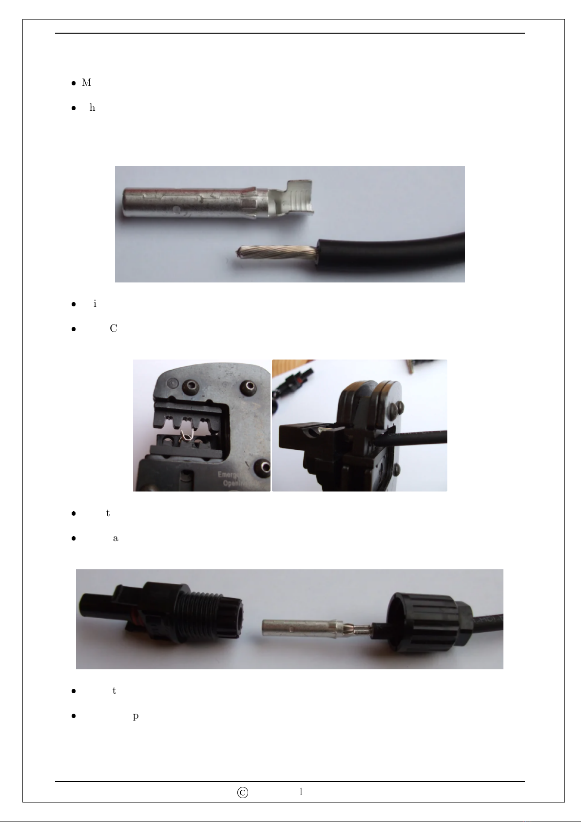
Strip cables, only multiple strands of copper wire can be used. Please cut and strip the wire
according to the requirements, and the ground wire needs to be 5 mm longer than live and
neutral wire, and the applicable stripping length is 7-8 mm.
©
Pyramid Electronics
5KW 3-Phase Grid Tied Solar Inverter 11
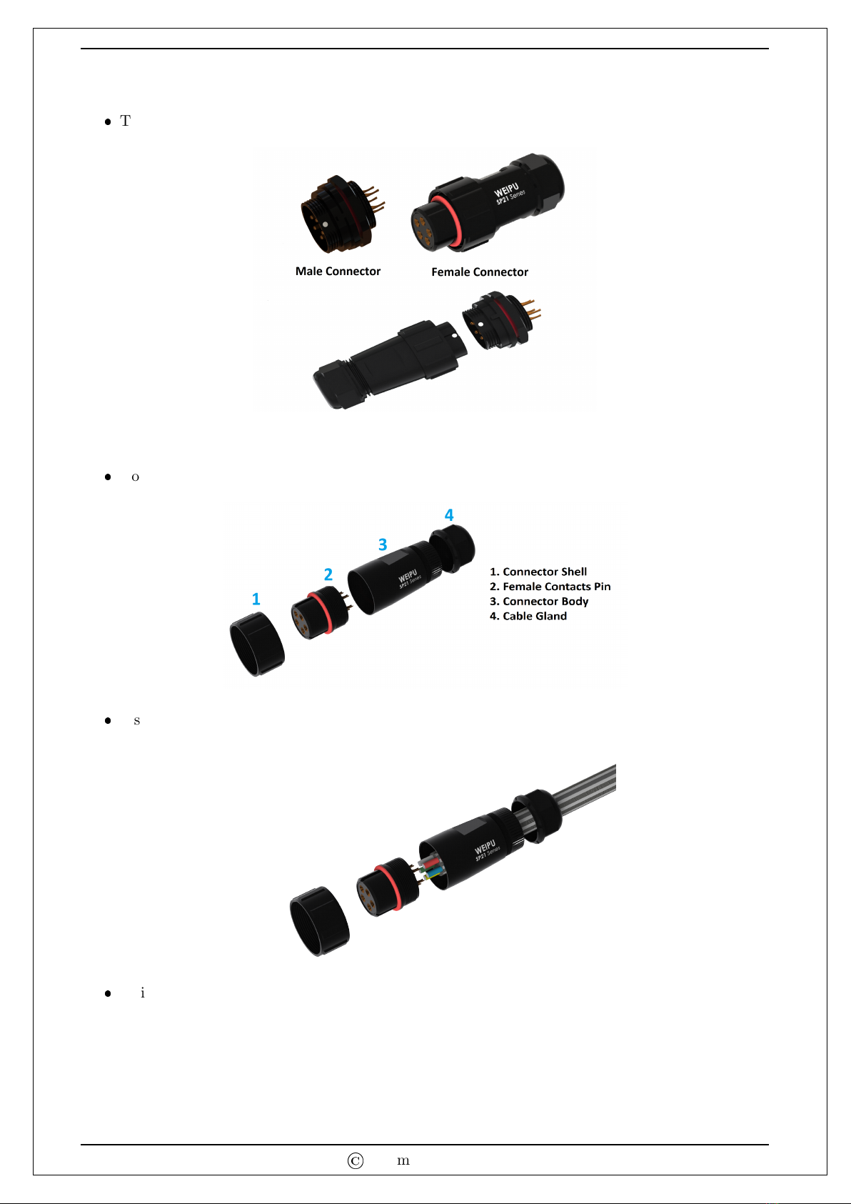
Instruction of cable connector assembly
The male and female part of 5 pin three phase AC connector has been shown below.
Note: Male part will already be connected to the solar inverter body.
Now three phase 5 wire cable has to be connected to the female part of connector shown below.
Install the cable gland and connector body to the cable.
Strip the cable outer jacket, trim and strip each insulation, then solder the female contact pin
on each conductors as shown in figure.
©
Pyramid Electronics
5KW 3-Phase Grid Tied Solar Inverter 12
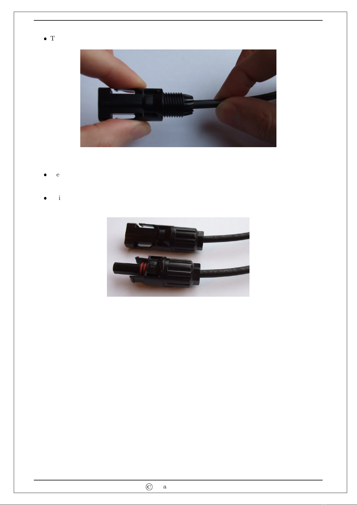
Finally tighten the cable gland.
Note: Before connecting female connector to the male part, match the white dot
provided on both connector and then insert the female connector. Finally tighten the
connector shell.
5.2 Solar (DC) Connection
Note that the present inverter is a functionally ungrounded array solar inverter. This means that none
of the input dc terminals (PV+ or PV-) can be connected to earth/ground. If any of the dc input
terminals is connected to ground, the inverter will not start-up and can lead to permanent damage of
the inverter.
5.2.1 PV Terminal Connections
Caution: Solar PV String can be directly connected to the solar inverter without using any DC
circuit breaker.
Note: Automatic built-in dc switch exists within the inverter. The control electronics of the inverter
is powered up from the grid side. Basically, the inverter WILL NOT turn ON once the solar string is
connected. The inverter will only be turned on once the grid side circuit breaker is turned ON. Note:
Please use 1000 V DC / 20 A circuit breaker for the present 5 KW 3 Phase Grid-Tied Solar Inverter
if required.
WARNING!! This inverter is compatible with any type of PV modules: single crystalline, poly
crystalline and thin film PV.
Check the input voltage of PV array modules. The acceptable input voltage of solar inverter is
100 V DC - 1000 V DC. This system has a single input, please make sure that the maximum
current of PV input connector is less than or equal to 17 A for present 5 KW 3 Phase Grid Tied
Solar Inverter.
CAUTION: Exceeding the maximum input voltage can destroy the unit!! Check the system
before wire connection.
©
Pyramid Electronics

5KW 3-Phase Grid Tied Solar Inverter 13
Disconnect the circuit breaker.
Check correct polarity of connection cable from PV modules and PV input connectors. Then,
connect positive pole (+) of connection cable to positive pole (+) of PV input connector. Connect
negative pole (-) of connection cable to negative pole (-) of PV input connector.
WARNING! It’s very important for system safety and efficient operation to use appropriate cable
for DC connection. To reduce risk of injury, please use the proper recommended
cable size as below.
Table 2: Suggested cable requirement for DC wire (PV+ and PV-)
Model Conductor Cross-Section
5 KW 3 Phase >= 4mm2
CAUTION: Never directly touch terminals of the inverter. It will cause lethal electric shock.
Outline size of MC4 Solar connector
MC4 is the name of the connection type on all new solar panels, providing an IP-67 waterproof
and dust proof safe electrical connection. MC4 will not connect with older MC3 type connectors.
The MC4 connectors work best with 4 mm2and 6 mm2solar cable.
Components needed are: cable, a male and female MC4 connector, wire strippers, some wire
crimps.
©
Pyramid Electronics
5KW 3-Phase Grid Tied Solar Inverter 14
Assemble provided PV- connectors by following below steps:-
MC4 Female Connector Fitting.
The wire is stripped shorter than the metal crimp connector. There is a mark on the metal to
indicate how far the other connector will enter into this one, if cable extends past this mark
in the connector, then it will not be able to join the MC4 connectors together. Recommended
cable stripping length is between (10 - 15) mm.
Crimp the cable.
An MC4 (4 - 6) mm2crimp connector is used because it gives a great connection every time
and holds all the bits in place when you crimp.
Pass the screw nut over the metal crimp first.
The plastic housing has a non return clip inside and if you have not put the nut on the cable
first, you will not be able to get the plastic housing off without damaging it and rendering it.
Insert the cable.
When you push the crimped cable into the connector, you will hear a ‘CLICK’. This is the non
return clip locking the crimp into the plastic housing.
©
Pyramid Electronics

5KW 3-Phase Grid Tied Solar Inverter 15
Looking closely at the picture we will see that the rubber seal washer is flush with the end of
the plastic fingers around the cable.
This will give the best grip on 4 mm cable when the nut is tightened onto the plastic housing.
If we do not do this with 4 mm cable, the connector will be able to spin around the cable and
over time may damage the connection. Final MC4 Female Connector has shown below.
Assemble provided PV+ connectors by following below steps:-
MC4 Male Connector Fitting.
Put a little bend in the cable for better surface contact inside the crimp. This cable insulation
is stripped by 15 mm to expose the wire for crimping as done in above steps.
Insert the cable.
Again pass the screw nut over the cable first. Check the rubber washer as in above step and
push the crimped cable into the female housing until you hear the ’CLICK’.
©
Pyramid Electronics
5KW 3-Phase Grid Tied Solar Inverter 16
Tighten the nut onto the male plastic housing. Final MC4 Male Connector has shown below.
Test Before Connecting
We would advise you to test the continuity of your cable with the new MC4 connectors, before
connecting to your solar panels.
This will confirm you have a good connection that will last for years. Please remember never
disconnect the connectors when in operation, it can cause a serious injury.
5.3 GSM / WiFi Connection
Connect the two antennas provided in the packaging box. Only tighten the antennas to the screw
provided on solar inverter body. The inverter has built-in GSM (SIM) and WiFi and can be connected
to the internet for remote monitoring.
©
Pyramid Electronics

5KW 3-Phase Grid Tied Solar Inverter 17
6 Turning the Inverter ON
Summary of steps to be followed to turn ON the inverter is as follows:
1. Mount the inverter on the wall as discussed in Section 4.
2. Connect the solar PV string to the inverter as detailed in Section 5 (Note that inverter will not
turn ON at this stage).
3. With the grid side MCB turned OFF, make the grid side connection as detailed in section 5.
4. Connect the antennas as detailed in Section 5.
5. With all the connections done, simply turn on the grid side MCB. The inverter should now be
turned ON provided grid is available.
6. Upon turn ON, the inverter checks whether the PV side and grid side voltages are within limits
and provides information regarding the same using the LED indications. With the PV side and
grid side voltage within limits, the inverter next performs Insulation Resistance (IR) test of the
PV terminals w.r.t. the earth. Once this test is passed, the inverter starts to feed power to the
grid. If the IR test fails or some other fault is present, it will be indicated through the LED
indication. In case the Fault LED indication glows upon turning on the Inverter, please contact
the system installer. In case there is no fault in the inverter, the Inverter ON LED indication
glows, and LCD displays “Initializing” for around 30 seconds.
7. After 30 seconds, the inverter tries to connect to the server first using the WiFi and then using
GSM. When the inverter is turned ON for the first time, obviously the inverter will not be able
to connect to the server using WiFi. If the GSM for the inverter is activated, the inverter will get
connected to the server instantly (provided network connectivity is available). Whether GSM is
activated or not can be seen from the packing box of the inverter. If the GSM box is ticked on
the packing, that means GSM is activated otherwise not.
8. After successful or unsuccessful connection to the server, the LCD will display information as
shown in Figure 2 on page 34.
9. If WiFi connection is available near the inverter, then the inverter can be connected to the WiFi
as discussed in next section.
10. For remote monitoring, both the Web-App as well as Mobile-App (both android and IOS ver-
sions) are available. For activating remote monitoring, follow the steps detailed in the next
section.
7 Remote Monitoring for Users
7.1 Configuring GSM/WiFi Module of Solar Inverter
Connection of GSM Module
There is no manual procedure required for connection of GSM module to the server.
The GSM module inside the inverter is already activated, provided the user has paid for the
GSM postpaid SIM.
When inverter turns ON, it will try to connect automatically to the server (provided that SIM
network is available).
©
Pyramid Electronics
5KW 3-Phase Grid Tied Solar Inverter 18
Connection of WiFi Module
To connect the inverter to the WiFi, user has to manually fill the password of WiFi network
available there.
To fill the password, user should use the push buttons provided on LCD display of solar inverter.
First user should long press the ‘Back’ button on display to reach ‘Change WiFi Network ?’ on
LCD screen, and then press ‘Enter’ button.
LCD will now show the WiFi connections available there. If no connections are available, then
after 3 seconds it will try to connect to GSM and will automatically reach the default ‘Measure-
ment’ screen.
If the LCD shows the WiFi connections available, then user can connect to the desired network
by using ‘Up’ and ‘Down’ buttons on display and press ‘Enter’.
Now display will read ‘Enter Password’.
Table 3: ASCII Chart Reference to Set WiFi Password
! 9 Q i
” : R j
# ; S k
$
<T l
% = U m
&>V n
’ ? W o
( @ X p
) A Y q
* B Z r
+ C [ s
, D \t
- E ] u
. F ˆ v
/ G w
0 H ` x
1 I a y
2 J b z
3 K c {
4 L d |
5 M e }
6 N f ∼
7 O g
8 P h
An example for entering the password is detailed next:
–Suppose the password to be entered is: 123abc.
–To enter the password, keep the “ Up” button pressed till the character “1” is reached.
–Press Enter and then the second character is to be entered (that is “2”).
–Continuing the same way, user needs to enter all the characters of the password (maximum
of 32 characters are allowed).
©
Pyramid Electronics

5KW 3-Phase Grid Tied Solar Inverter 19
–Once the last character is reached, that is “c” in this example, the user needs to press
the “Back” button and NOT the “Enter” button as was the case with previous characters.
Pressing the enter button once the last character is reached will lead to an unsuccessful
connection.
User can refer Table 3 on page 18 to get an idea about the sequence of characters available
to enter the password.
If the entered password is correct then display will show ‘WiFi Connected Successfully’ and it
will automatically reach the default ‘Measurement’ loop and start to show the meter readings.
If WiFi module is unable to connect, then it will try to connect with the GSM as mentioned in
above step.
User can also take the help of flow chart provided on Figure 3 on page 35.
Note: If the user gets stuck anywhere on display screen, then press ‘Back’ button to reach the
default ‘Measurements?’ tab and press ‘Enter’ to enter the default loop.
7.2 Remote Monitoring Using Web App
The steps for using Web App are as follows:
Type www.pyramidsolar.in in any web browser and hit enter.
It will open the home page on screen as shown below.
Now click on ‘SignUp Now’ and a new page will appear on screen as shown below.
Enter all the details and click on ‘Register’ button.
©
Pyramid Electronics
Table of contents
Popular Inverter manuals by other brands


Hoymiles
Hoymiles HM-2000T-S Series Quick installation guide

ABB
ABB UNO-DM-6.0-TL-PLUS-Q Quick installation guide

Boston gear
Boston gear 700 Series Installation and operation

Zipper Mowers
Zipper Mowers ZI-STE6500 Operation manual

Carrier
Carrier ASPAS1CCA007 owner's manual

G-Power America
G-Power America GN10000DEW owner's manual


