WWW.LONGS-MOTOR.COM
7
6. Adjustment of troubleshooting
1) , the status on light’s indication
PWR: green, normal work light.
ALM: red, failure light, the motor with phase short-circuit, overvoltage and under-voltage
protection.
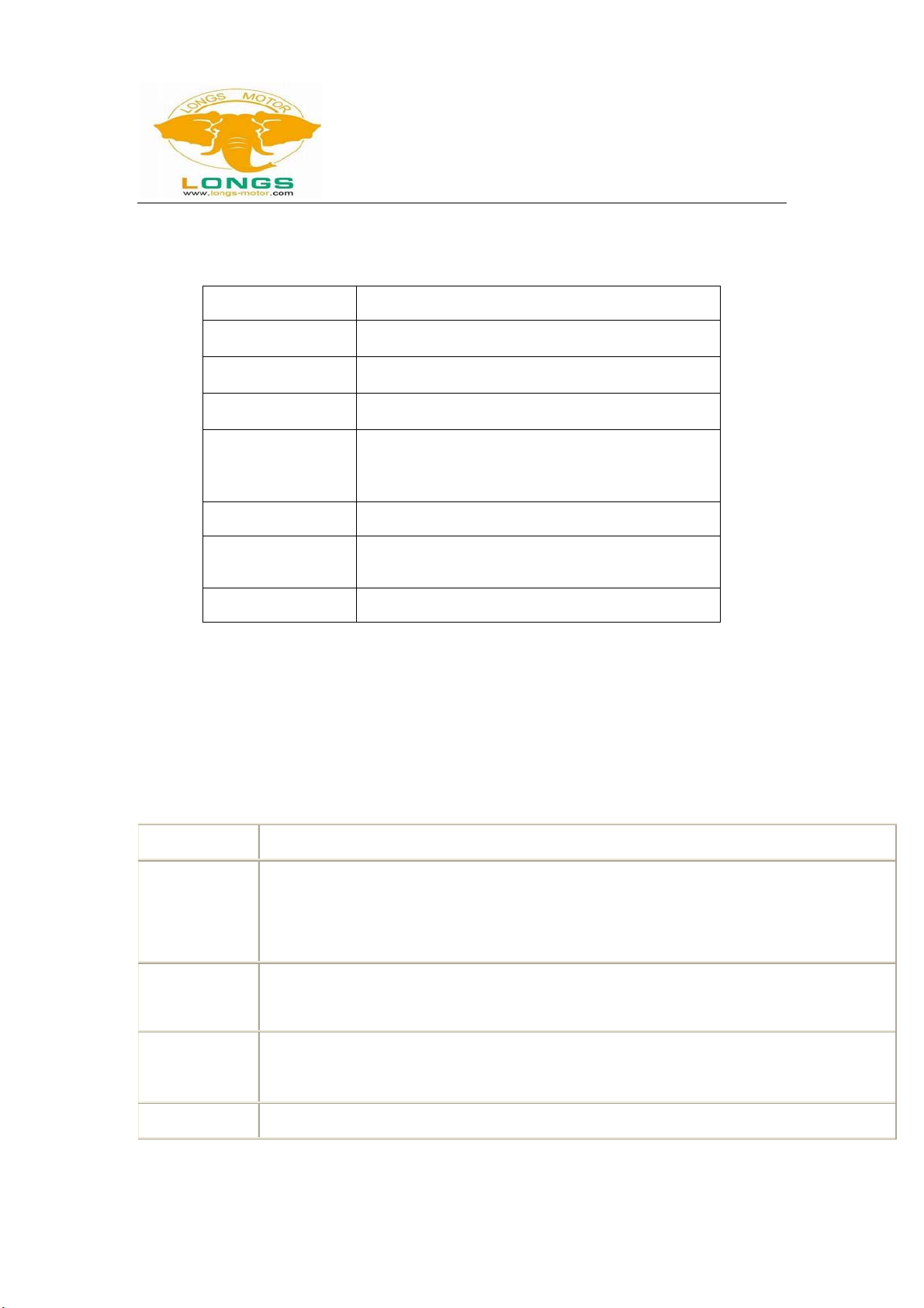
2) Troubles
Alarm indicator
Reasons Measures
Wrong connection for power Check wiring of power
LED off turn Low-voltages for power Enlarge voltage of power
Wrong connection of stepper
motor Correct its wiring
Motor doesn’t run, without
holding torque RESET signal is effective
when offline Make RESET ineffective
Motor doesn’t run, but
maintains holding torque Without input pulse signal Adjust PMW & signal level
Wrong wires’ connection Change connection for any of
2 wires
Motor runs wrong direction Wrong input direction signal Change direction setting
Too small relative to current
setting Correct rated current setting
Acceleration is too fast Reduce the acceleration
Motor stalls Rule out mechanical failure
Motor’s holding torque is
too small
Driver does not match with the
motor Change a suitable driver
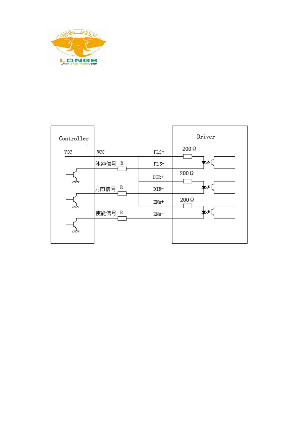
7. Driver wiring
A complete stepper motor control system should contain stepper drives, DC power supply and
controller (pulse source). The following is a typical system wiring diagram