Loren Cook HVAD 2020 Guide

1
InstallationInstallation
& Operation& Operation
User GuideUser Guide
®
HVADHVAD

2
Table of ContentsTable of Contents
TABLE OF CONTENTSTABLE OF CONTENTS................................................................................................................................ 22
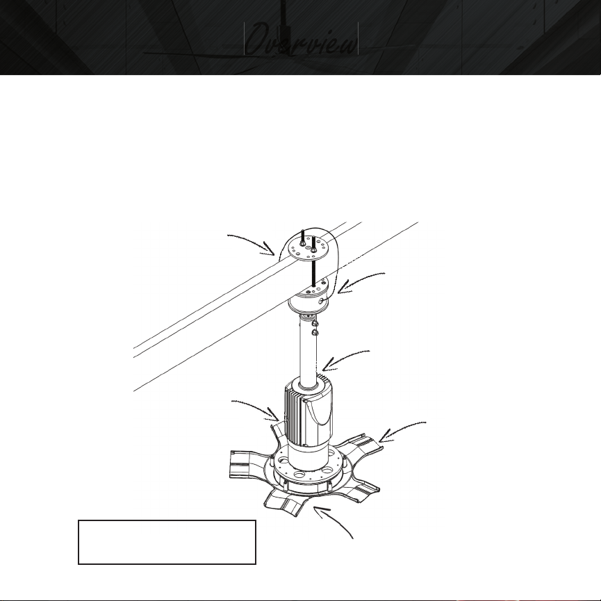
OVERVIEWOVERVIEW.................................................................................................................................................................. 44
COMPONENTS ....................................................................... 4
TECHNICAL DATATECHNICAL DATA .......................................................................................................................................... 55
FUSING & THERMAL LIMITINGFUSING & THERMAL LIMITING .................................................................................................. 77
FUSES...................................................................................... 7
THERMAL LIMITING................................................................ 7
SAFETYSAFETY.............................................................................................................................................................................. 88
ELECTRICAL SAFETY................................................................ 8
GENERAL SAFETY.................................................................... 9
CLEARANCES .......................................................................... 10
INSTALLATION PREPARATIONINSTALLATION PREPARATION.................................................................................................... 1212
PREPARATION ........................................................................ 12
TOOLS REQUIRED .................................................................. 13
ITEMS INCLUDED ................................................................... 14
HARDWARE INCLUDED ......................................................... 14
INSTALLATION PROCEDUREINSTALLATION PROCEDURE.......................................................................................................... 1616
INSTALLATION OF THE MOUNTING HARDWARE ................ 16

3
INSTALLING THE MOTOR ASSEMBLY .................................... 24
INSTALLING BLADES .............................................................. 26
INSTALLING THE OPTIONAL LED LIGHT KIT ......................... 27
INSTALLING THE HUB COVER (WITH LENS) ......................... 29
ELECTRICAL INSTALLATIONELECTRICAL INSTALLATION............................................................................................................ 3030
WIRING THE FAN ................................................................... 30
HMI CONTROLHMI CONTROL.................................................................................................................................................... 3333
HMI/CAT 5 CABLE CONNECTION .......................................... 33
MAINTENANCEMAINTENANCE.................................................................................................................................................... 3535
RECOMMENDED MAINTENANCE SCHEDULE........................ 36
LIMITATION OF WARRANTY & LIABILITYLIMITATION OF WARRANTY & LIABILITY.................................................................. 3838
THREE YEAR LIMITED WARRANTY ......................................... 38
WARRANTY EXCLUSIONS ...................................................... 39
WARRANTY DURATION......................................................... 41
WARRANTY CLAIM INSTRUCTIONS....................................... 42
FIFTEEN YEAR SERVICE LIFE PRORATED WARRANTY............. 43
FIFTEEN YEAR SERVICE LIFE PRORATED WARRANTY FORM.. 49

4
OverviewOverview
EN022X2222 [3 mm] 3/32”
Aluminum Crimp
(2) EN823X6955 [3 mm] 1/8”
Cable Clamp Zinc
EN561X2505 Mount Assembly
Optional Custom Lengths
Available
LED Light Kit EN561X3675
Or Lens (below)
Hub Cover
COMPONENTSCOMPONENTS
Illustrations may be changed without notice. All dimensions and
specifications are approximate, and drawings are not to scale. Sales are
subject to prevailing terms and conditions of sale. Specifications are subject
to change without notice.
See Mounting Applications
EN575X0010
Motor Assembly
(5) HVAD Blades (Not Shown)
Note: All bolts are “Grade 5”
(#) = Quantity Supplied

5
Technical DataTechnical Data
Conformity CE Low Voltage (2006/95/EC) & EMC
(2004/108/EC) Directives
EN61000-6-2:2005, EN61000-6-4:2007
IEC 60335-2-80:2015 IEC 60335-1:2015
Approvals UL61800-
5-1
CSA C22.2
No113
Input Voltage Phase
Imbalance
≤2%
Input Voltage 110-240 VAC
Input Current 4.6 @ 120VAC, 2.5A @ 240VAC
Input Frequency 50-60Hz
Supported Power Systems TT TN For central ground systems, operation is
permitted without restrictions.
Humidity ≤95% Non-condensing
Temperature Range Transport -40°C…+70°C
Storage -40°C…+70°C
Operation -40°C…+50°C (with speed derating above
+40°C)
Installation Height 0 – 4000
a.m.s.l
(with 5%/1000m current derating above
1000m a.m.s.l)
Earth Leakage Current <=9 mA to PE
Power Conductor Size
(Cord)
Minimum 16AWG 3 Conductors rated 300VAC, use Cop-
per Conductors only. For permanent connection only.

6
Max. Permissible Control
Cable Length
30 meters un-shielded
Enclosure IP54/ NEMA 3
Protection Measures Against Short circuit, earth fault, phase loss, over voltage, under
voltage, motor stalling, over temperature, motor overload,
communication loss
Environment For indoor use only
Thermal Overload Protec-
tion
Drive provides internal overload protection for the motor
Pollution Degree 2
Overvoltage Category Category lll
Supply Earthing System TN-S
Impulse Voltage 2500V
Working System Voltage 150V
Packaged Fan Weight 98 lbs (44.5 kgs)
Overall Fan Weight (no
mount)
85 lbs (38.5 kgs)
LED Light Kit Weight 1.542 lbs (0.669 kgs)

7
Fusing & Thermal LimitingFusing & Thermal Limiting
FUSESFUSES
It is recommended that the following fuses for protecting the equipment
and subject to local authority:
For 220-240 VAC use a fast blow fuse rated 5 Amps.
For 110-120 VAC use a fast blow fuse rated 10 Amps.
THERMAL LIMITINGTHERMAL LIMITING
The HVAD System is designed to monitor motor and controller
temperatures and, in the event, that operating temperatures exceed
control limits, fan speed will automatically reduce until the system is
within temperature limits. No user intervention is required.

8
SafetySafety
ELECTRICAL SAFETYELECTRICAL SAFETY
WARNING! IGNORING THE FOLLOWING INSTRUCTIONSWARNING! IGNORING THE FOLLOWING INSTRUCTIONS
CAN CAUSE PHYSICAL INJURY OR DEATH, OR DAMAGE TOCAN CAUSE PHYSICAL INJURY OR DEATH, OR DAMAGE TO
THE EQUIPMENT.THE EQUIPMENT.
WARNING! ONLY QUALIFIED ELECTRICIANS ARE ALLOWEDWARNING! ONLY QUALIFIED ELECTRICIANS ARE ALLOWED
TO INSTALL THE DRIVE AND CONNECTIONS TO THETO INSTALL THE DRIVE AND CONNECTIONS TO THE
MOTOR!MOTOR!
Never work on the drive, motor cable or motor when input power is
applied. After disconnecting the input power, always wait for 5 minutes to
let the intermediate circuit capacitors discharge before you start working
on the drive, motor or motor cable.
Do not work on the control cables when power is applied to the drive
or to the external control circuits. Externally supplied control circuits
may carry dangerous voltage even when the input power of the drive is
switched off.
The Touch Current of the Protective Earthing Conductor could reach up toThe Touch Current of the Protective Earthing Conductor could reach up to
9mA AC.9mA AC.

9
GENERAL SAFETYGENERAL SAFETY
WARNING! TO REDUCE THE RISK OF FIRE, ELECTRIC SHOCK,WARNING! TO REDUCE THE RISK OF FIRE, ELECTRIC SHOCK,
OR INJURY TO PERSONS, OBSERVE THE FOLLOWING:OR INJURY TO PERSONS, OBSERVE THE FOLLOWING:
• Installation work and electrical work must be done by qualified
person(s) in accordance with all applicable codes and standards,
including fire-rated construction.
• The installation is to be in accordance with the National
Electrical Code, CSA C22.1, ANSI/NFPA 70, and local codes.

10
CLEARANCESCLEARANCES

11
• Open ceiling, center of fan to roof deck for ideal operating
performance without compromising overall fan performance.
• Min 12” [304.8 mm] from fan blade’s leading edge to
obstruction above or below fan.
• Min 8” [203 mm] from side of fan to any obstruction.
• Min floor to fan leading edge height 120” [3050 mm].
Contractor is responsible for verifying all site conditions to include field
dimensions where applicable. If the contractor elects to make any changes
without notifying Cook the contractor is responsible for the same. All
drawings are to be used as general architectural intent unless otherwise
stamped. See Engineer drawings for structural design information.
Contractor to ensure that all building departments and authorities are
informed in regard to the work and that all permits are attained before
commencing work.

12
Installation PreparationInstallation Preparation
PREPARATIONPREPARATION
WARNING! TO REDUCE THE RISK OF FIRE, ELECTRIC SHOCK,WARNING! TO REDUCE THE RISK OF FIRE, ELECTRIC SHOCK,
OR INJURY TO PERSONS, OBSERVE THE FOLLOWING:OR INJURY TO PERSONS, OBSERVE THE FOLLOWING:
• The HVAD must be installed with the proper blades to match
the fan assembly that are marked to indicate their suitability
with this model.
• No other blades can be substituted.
• Check to see if you have all the tools required for the
installation.
• Verify that all fan components were received.
• Check drawings and layouts provided to locate where the
HVAD is to be installed.
• Ensure work area is safe and that all security, policies and
procedures for the facility are met.
• Inspect the lift device or mobile platform.
• Each person installing the HVAD must use a safety harness at all
times.
• Other safety requirements may be required for installation.
• All workspace safety requirements, lock out procedures and
hoarding of construction zone for the assembly and installation
must be met and followed.

13
• This appliance is not intended for use by persons (including
children) with reduced physical, sensory or mental capabilities,
or lack of experience and knowledge, unless they have been
supervised or instruction concerning use of the appliance by a
person responsible for their safety.
• Children should be supervised to ensure that they do not play
with the appliance.
• The mounting of the suspension system shall be performed by
the manufacturer, its service agent or suitably qualified persons.
• DO NOT LIFT, CARRY OR HANG FAN BY POWER CABLE.
This could possibly cause the safety disconnect system to
disconnect power to the fan.
TOOLS REQUIREDTOOLS REQUIRED
• Level
• Ratchet or impact gun
• 3/8”, 7/16” and 9/16” Imperial socket to fit bolt heads and nuts
• 7/16” and 9/16” Imperial wrench to fit bolt heads and nuts
• #2 Phillip screwdriver
• Lifting device or scaffolding
• Appropriate personal protective equipment
• Drill & drill bit set up to ½” diameter (optional)

14
ITEMS INCLUDEDITEMS INCLUDED
• (1) EN575X0010 HVAD Motor Assembly
• (5) HVAD Blades (Optional Color)
• (1) EN561X3660 HVAD LF/SP Assembly
• (1) EN561X6205 Packaged Assembly Hardware
• (1) EN561X3570 Packaged HMI Control
• (1) EN561X3635 Packaged Wire Harness
• (1) EN561X3675 HVAD LED Light Kit (Or Lens)
• (1) Hub Cover (Optional Color)
HARDWARE INCLUDEDHARDWARE INCLUDED
• (1) EN562X1100 HVAD Mounting Plate
• (2) EN562X1152 HVAD Mounting Brackets
• (3) EN823X8313 3/8 x 9” B7 Threaded Rod W/ Nut
• (2) EN022X1022 Hex Cap Screw 3/8” X 3”
• (5) EN823X6999 3/8 Nylocks
• (10) EN823X6381 3/8 Flat Washers
• (20) EN823X6030 ¼ x 5/8 Serrated Flange Head Cap Screw
• (5) EN823X6119 #8-32 x 1 3/8 Machine Screw
• (1) EN823X6955 1/8” Cable Clamp
• (1) EN562X2510 Studded Mount Assembly

15
• (8) EN823X6905 ¼ Flat Washers
• (8) EN823X6312 ¼ Nylocks
• (4) EN823X6031 ¼ x 1 ¼ Hex Cap Screw
• (3) EN823X6008 3/8 x 1 ½ Hex Cap Screw
• (1) EN562X2540 HVAD Stand Off Ring
NOTE: Illustrations may be changed without notice. All dimensions and
specifications are approximate and drawings are not to scale. Sales are
subject to prevailing terms and conditions of sale. Specifications are
subject to change without notice.

16
INSTALLATION OF THE MOUNTING HARDWAREINSTALLATION OF THE MOUNTING HARDWARE
NOTE: Consult a structural engineer before installation. Choose one
of the following mounting options for your HVAD Fan and follow the
corresponding steps. The mounting kits included in the HVAD Fan
package are glu-lam, purlin, OWSJ and web truss.
WARNING: USE OF ANY OTHER MOUNTING HARDWAREWARNING: USE OF ANY OTHER MOUNTING HARDWARE
OR TECHNIQUE IS STRICTLY PROHIBITED.OR TECHNIQUE IS STRICTLY PROHIBITED.
ONLY USE MOUNTING HARDWARE/ BRACKETS SUPPLIEDONLY USE MOUNTING HARDWARE/ BRACKETS SUPPLIED
BY COOK.BY COOK.
Installation ProcedureInstallation Procedure

17
GLU-LAM MOUNTGLU-LAM MOUNT
1. From an accessible landmark, on the glu-lam, measure to the
centre line of the bottom centered hole of the 3 mounting holes.
2. Drill the centered bottom mounting hole with a ½” drill bit, so
that there will be a minimum of ¾” (19mm) between the top of
the (EN562X1152) mounting bracket deck and the bottom of the
glu-lam.
3. Place the two (EN562X1152) mounting bracket faces one on
each side of the glu-lam with each mounting bracket bottom
deck face inward.
4. Before fastening the mounting brackets install four ¼” x 1-1/4”
long hex cap screws (EN823X6031) with ¼” flat washers
(EN823X6905) into mounting bracket deck facing down.

18
5. Using a 3/8” X 9” threaded rod with welded nut (EN823X8313)
and 3/8” nylock nut (EN823X6999), suspend the mounting
brackets using the center bottom hole only.
6. Level the mounting brackets and mark the centre of the top two
mounting holes. Drill the remaining top two mounting holes.
7. Before tightening the structural nuts and bolts, ensure the
bracket is plumb and level then proceed with tightening the
mounting brackets to the glu-lam.
8. Fasten studded mount assembly(EN562X2510) to four ¼” x
1-1/4” long hex cap screws (EN823X6031) already in place
using four ¼” flat washers (EN823X6905) and four ¼ nylocks
(EN823X6312).
9. Continue on to “Installing the Motor Assembly”.

19
PURLIN MOUNTPURLIN MOUNT
1. From an accessible landmark, on the first purlin, measure to the
centre line of the bottom centered hole of the 3 mounting holes.
2. Drill the centered bottom mounting hole with a ½” drill bit, so
that there will be a minimum of ¾” (19mm) between the top of
the (EN562X1152) mounting bracket deck and the bottom of the
purlin.
3. Place the two mounting bracket faces together with each bracket
bottom deck face outward.
4. Before fastening the mounting brackets install four ¼” x 1
1/4” long hex cap screws (EN823X6031) with ¼” flat washers

20
(EN823X6905) into slots in mounting bracket deck facing down.
5. Using a 3/8” X 1-1/2” hex cap screw (EN823X6008) and 3/8”
nylock nut (EN823X6999), suspend the mounting brackets using
the center bottom hole only.
6. Level the mounting brackets and mark the centre of the top two
mounting holes. Drill the remaining top two mounting holes.
7. Before tightening the structural nuts and bolts, ensure the
bracket is plumb and level then proceed with tightening the
mounting brackets to the purlin.
8. Fasten studded mount assembly(EN562X2510) to four ¼” x
1-1/4” long hex cap screws (EN823X6031) already in place
using four ¼” flat washers (EN823X6905) and four ¼ nylocks
(EN823X6312).
9. Continue on to “Installing the Motor Assembly”.
Table of contents
Other Loren Cook Industrial Equipment manuals