LORENZ MESSTECHNIK DR-3000 User manual

LORENZ MESSTECHNIK GmbH
Obere Schloßstr.131
D-73553 Alfdorf
+49 7172/93730-0
Fax +49 7172/93730-22
E-Mail: info@lorenz-sensors.com
Technical changes under reserve
090307d_DR_3000_en.doc
Internet: www.lorenz-sensors.com
Page 1 of 13
Operation Manual for
“Plug and Play“
USB Torque Sensor
Type DR-3000

LORENZ MESSTECHNIK GmbH
Obere Schloßstr.131
D-73553 Alfdorf
+49 7172/93730-0
Fax +49 7172/93730-22
E-Mail: info@lorenz-sensors.com
Technical changes under reserve
090307d_DR_3000_en.doc
Internet: www.lorenz-sensors.com
Page 2 of 13
1 Contents
1Contents ..............................................................................................................................................................................2
2Imprint .................................................................................................................................................................................3
3References in this Text.......................................................................................................................................................3
4Read First ............................................................................................................................................................................4
4.1 Safety and Caution Symbols....................................................................................................................................4
4.2 Intended Use ...........................................................................................................................................................4
4.3 Dangers...................................................................................................................................................................4
4.3.1 Neglecting of Safety Notes..........................................................................................................................4
4.3.2 Remaining Dangers ....................................................................................................................................4
4.4 Reconstructions and Modifications...........................................................................................................................4
4.5 Personnel ................................................................................................................................................................4
4.6 Warning Notes.........................................................................................................................................................5
5Term Definitions..................................................................................................................................................................5
5.1 Terms ......................................................................................................................................................................5
5.2 Definition of the Pictograms on the Torque Sensor ..................................................................................................5
6Product Description............................................................................................................................................................6
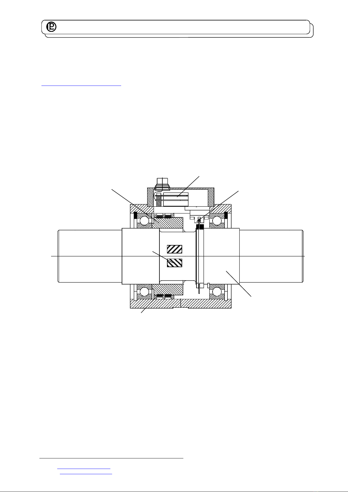
6.1 Mechanical Setup ....................................................................................................................................................6
6.2 Electrical Setup........................................................................................................................................................6
6.3 Angle of Rotation- and Speed Measurement............................................................................................................7
6.4 Sensor Communication............................................................................................................................................7
7Mechanical Assembly.........................................................................................................................................................8
7.1 Couplings ................................................................................................................................................................8
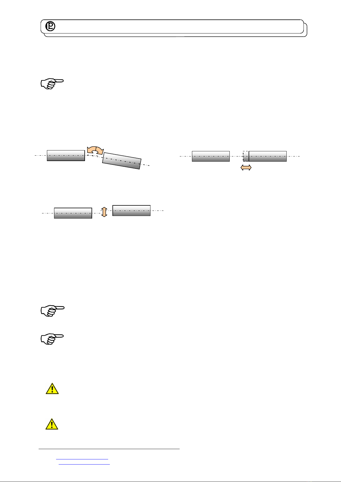
7.1.1 Misalignment Possibilities of Single-Jointed Couplings................................................................................8
7.1.2 Double-Jointed Couplings ...........................................................................................................................8
7.1.3 Alignment of the Measurement Arrangement ..............................................................................................8
7.2 General....................................................................................................................................................................8
7.2.1 Torque Sensors of 0.1 N·m to 10 N·m.........................................................................................................8
7.3 Free-floating Assembly ............................................................................................................................................9
7.4 Foot Version Assembly ............................................................................................................................................9
8Electrical Connection .......................................................................................................................................................10
8.1 USB - Cable...........................................................................................................................................................10
8.2 Shielding Connection.............................................................................................................................................10
8.3 Running of the Transmission Cables......................................................................................................................10
8.4 Drivers and Software .............................................................................................................................................10
8.5 Calibration Control .................................................................................................................................................10
9Measuring..........................................................................................................................................................................10
9.1 Engaging ...............................................................................................................................................................10
9.2 Direction of Torque ................................................................................................................................................11
9.3 Static / Quasi-Static Torques .................................................................................................................................11
9.4 Dynamic Torques...................................................................................................................................................11
9.4.1 General .....................................................................................................................................................11
9.4.2 Natural Resonances..................................................................................................................................11
9.5 Speed Limits..........................................................................................................................................................11
9.6 Disturbance Variables............................................................................................................................................11
10 Maintenance ......................................................................................................................................................................12
10.1 Maintenance Schedule (recommended).................................................................................................................12
10.2 Trouble Shooting ...................................................................................................................................................12
11 Decommission ..................................................................................................................................................................12
12 Transportation and Storage .............................................................................................................................................12
12.1 Transportation .......................................................................................................................................................12
12.2 Storage..................................................................................................................................................................13
13 Disposal.............................................................................................................................................................................13
14 Calibration.........................................................................................................................................................................13
14.1 Proprietary Calibration ...........................................................................................................................................13
14.2 DKD-Calibration.....................................................................................................................................................13
14.3 Re-Calibration........................................................................................................................................................13
15 Data Sheet .........................................................................................................................................................................13
16 Literature ...........................................................................................................................................................................13

LORENZ MESSTECHNIK GmbH
Obere Schloßstr.131
D-73553 Alfdorf
+49 7172/93730-0
Fax +49 7172/93730-22
E-Mail: info@lorenz-sensors.com
Technical changes under reserve
090307d_DR_3000_en.doc
Internet: www.lorenz-sensors.com
Page 3 of 13
2 Imprint
Manufacturer, Place
Lorenz Messtechnik GmbH, D-73553 Alfdorf
Valid for...
Torque Sensor Type DR-3000
Copyright
© 2008-2010 Lorenz Messtechnik GmbH, Alfdorf
Reprint-Interdiction
Reprint, even in extracts, only with written authorization from Lorenz
Messtechnik GmbH.
Modification
Technical changes reserved.
3 References in this Text
4.6 Warning Notes; Page 5
Attention must be paid to the accident prevention regulations of the trade associations.
Coverings and casings are necessary before operating the sensor. This is also valid for
commissioning, maintenance and trouble shooting.
Duties of the coverings and casings are:
Protection from detaching parts
Protection from contusion and shear
Prevention from reaching rotating parts
Prevention from being tangled up and/or getting caught by parts
Coverings may
Not grind, Not rotate
Coverings are also necessary outside of operating and motion travel areas of persons.
These demands can be modified if other sufficient safety devices are available. During
operation, the safety precautions must be operative. By vibrations, damages can occur at
the device.
7 Mechanical Assembly; Page 8
During the assembly, the sensor must be protected from falling down.
7.1.3 Alignment of the Measurement Arrangement; Page 8
For further references see the coupling manual of the coupling manufacturer and/or the
data sheet.
7.2 General; Page 8
Before the assembly, shafts must be cleaned with dissolver (e.g. acetone), no foreign
particles may adhere to them. The hub must fit according to the connection.
Caution: During the assembly inadmissibly large forces may not act on the sensor or the
couplings. Especially at small torques (<20 N·m) we strongly recommend to connect the sensor
electrically during the assembly and watch the signal. The measuring signal may not exceed the
nominal torque.
7.2.1 Torque Sensors of 0.1 N·m to 10 N·m; Page 8
Sensors with nominal torques up to 10 N·m are very sensitive to overload, therefore these sensors
must to be handled with major caution.
7.3 Free-floating Assembly; Page 9
Caution: Inadmissibly large forces may not act on the sensor or the couplings during the assembly.
Double-jointed couplings for both sides cannot be used in this installation case.
Risk of breakage!
In this installation case the rotational speed must be limited <10000 rpm!
Risk of breakage by resonance appearances.
7.4 Foot Version Assembly; Page 9
Caution: Inadmissibly large forces may not act on the sensor or the couplings during the assembly.
9.1 Engaging; Page 10
Warming-up period of the torque sensor is approx. 5 min. This time period can deviate significantly
(ambient temperature).
9.4.2 Natural Resonances Page 11
Operation of the equipment in natural resonance can lead to permanent damages.

LORENZ MESSTECHNIK GmbH
Obere Schloßstr.131
D-73553 Alfdorf
+49 7172/93730-0
Fax +49 7172/93730-22
E-Mail: info@lorenz-sensors.com
Technical changes under reserve
090307d_DR_3000_en.doc
Internet: www.lorenz-sensors.com
Page 4 of 13
4 Read First
4.1 Safety and Caution Symbols
Caution:
Injury Risk for Persons
Damage of the Device is possible.
Note:
Important points to be considered.
4.2 Intended Use
Torque sensors are intended for the measurement of torques. This measurand is further suitable for
control tasks. The valid safety regulations should be absolutely respected. The torque sensors are not
safety components in the sense of the intended use. The sensors need to be transported and stored
appropriately. The assembly, commissioning and disassembling must take place professionally.
4.3 Dangers
The torque sensor is fail-safe and corresponds to the state of technology.
4.3.1 Neglecting of Safety Notes
At inappropriate use, remaining dangers can emerge (e.g. by untrained personnel). The operation manual
must be read and understood by each person entrusted with the assembly, maintenance, repair,
operation and disassembly of the torque sensor.
4.3.2 Remaining Dangers
The plant designer, the supplier, as well as the operator must plan, realize and take responsibility for
safety-related interests for the sensor. Remaining dangers must be minimized. Remaining dangers of the
torque measurement technique must be pointed out.
Human mistakes must be considered. The construction of the plant must be suitable for the avoidance of
dangers. A danger-analysis for the plant must be carried out.
4.4 Reconstructions and Modifications
Each modification of the sensors without our written approval excludes liability on our part.
4.5 Personnel
The installation, assembly, commissioning, operation and the disassembly must be carried out by
qualified personnel only. The personnel must have the knowledge and make use of the legal regulations
and safety instructions.

LORENZ MESSTECHNIK GmbH
Obere Schloßstr.131
D-73553 Alfdorf
+49 7172/93730-0
Fax +49 7172/93730-22
E-Mail: info@lorenz-sensors.com
Technical changes under reserve
090307d_DR_3000_en.doc
Internet: www.lorenz-sensors.com
Page 5 of 13
4.6 Warning Notes
Attention must be paid to the accident prevention regulations of the trade associations.
Coverings and casings are necessary before operating the sensor. This is also valid for
commissioning, maintenance and trouble shooting.
Duties of the coverings and casings are:
Protection from detaching parts,
Protection from contusion and shear,
Prevention from reaching rotating parts,
Prevention from being tangled up and/or getting caught by parts.
Coverings may
Not grind, Not rotate
Coverings are also necessary outside of operating and motion travel areas of
persons.These demands can be modified if other sufficient safety devices are available.
During operation, the safety precautions must be operative. Vibrations can cause
damages on the device.
5 Term Definitions
5.1 Terms
Measuring Side:
Mechanical connection of the torque sensor in which the torque to be measured is applied. Usually this
side has the smallest moment of inertia.
Drive Side:
Mechanical connection of the torque sensor on the opposite side of the measuring side, usually with the
largest moment of inertia. At static torque sensors the housing is fastened on this side.
Low Torque Resistance Side:
The shaft of the arrangement (drive, load) which can be turned considerably smaller with torque than the
nominal torque of the torque sensor M << Mnenn .
5.2 Definition of the Pictograms on the Torque Sensor
The measuring side of the torque sensor is designated as follows:
Measuring side:
or M
More information can be found on the data sheet.
M

LORENZ MESSTECHNIK GmbH
Obere Schloßstr.131
D-73553 Alfdorf
+49 7172/93730-0
Fax +49 7172/93730-22
E-Mail: info@lorenz-sensors.com
Technical changes under reserve
090307d_DR_3000_en.doc
Internet: www.lorenz-sensors.com
Page 6 of 13
6 Product Description
The sensor measures static and dynamic torques. The mounting position of the torque sensor is
horizontally.
Caution: it is to be differentiated between measuring side and drive side, see data sheet of the sensor:
http://www.lorenz-sensors.com
6.1 Mechanical Setup
On the shaft which is located on the housing is an area, reduced at the diameter, on which the SG-bridge
is applied. The rotating part of rotating transformer and the rotating electronics are fixed on the shaft as
well.
A rotating transformer consists of two coils, concentrical to each other. The two coils are separated by an
air gap. By this, one coil can be fixed on the rotor and the other coil can be fixed in the stator. The
transmission of energy, resp. measuring signals occurs according the same principle as a transformer.
The stationary part of the rotating transformer and electronics are located in the housing. For the
electrical connection of the sensor a connector is located in the housing.
6.2 Electrical Setup
As mentioned in chapter 3.1, the measured value acquisition occurs on the rotating shaft through SG.
This measuring signal is immediately filtered, amplified and digitalized. The digital signal then goes to a
processor which prepares it in form of a serial word for the transmission to the stator. The transmission
from rotor to stator occurs through a rotating transformer. The great advantage of this rotating transformer
is its bidirectional use. Signals can be transferred from the rotating shaft to the stator as well as in
contrariwise direction. This is being used for the transmission of commands to the rotor and the control.
The data signal gets conditioned in the stator, then it is converted to a serial signal in a processor. This
serial signal is then translated into a USB-protocol by a converter. Then, the data are transferred to a PC
through an USB-connection. By the use of processors in a sensor, data such as serial number, calibration
value, measuring range etc. can be stored in the torque sensor. This information can be read-out for the
automatic configuration of the measurement software which leads to high reliability of operation.
Additional power supply is not necessary because the excitation of the sensor occurs via 5 V DC voltage
of the USB-interface.
If the 100 % calibration control is activated at the mechanical unloaded sensor, the SG measuring bridge
will be out of tune. At the output, a signal corresponding to nominal torque is being issued as a response.
SG
Rotating transformer
Shaft
Measuring side
Drive side
Electronics in the stator
Speed or angle sensor
Electronics in the rotor

LORENZ MESSTECHNIK GmbH
Obere Schloßstr.131
D-73553 Alfdorf
+49 7172/93730-0
Fax +49 7172/93730-22
E-Mail: info@lorenz-sensors.com
Technical changes under reserve
090307d_DR_3000_en.doc
Internet: www.lorenz-sensors.com
Page 7 of 13
By this, the function of the complete measurement chain can be checked, without having to load the
sensor with a reference variable.
Block diagram for sensor with integrated electronics.
6.3 Angle of Rotation- and Speed Measurement
The angle, resp. speed acquisition occurs in two different methods. At angle of rotation, only the flanks of
the TTL-signal of the angle sensor are processed, so that a pulse-shaped signal is available for each
flank. By this, two angle tracks with each 360 °/rev. 4 x 360 pulses, thus 1440 pulses are obtained, which
is equivalent to a dissolution of ¼ °. The information of rotating direction is obtained from the phase shift
of the two angle tracks.
The sensor does not issue the usual TTL-signals. It directly issues the conditioned angle signal in ¼-
degree-steps. By this, the correct angle of rotation for torque is always obtained.
At speed measurement a periodic durability measurement is carried out and from this, the speed is
determined. Also here, a TTL-signal as a value is not available, but directly the speed in unit rpm.
At speed and angle of rotation measurement the result is issued as a 16 bit-value by the sensor.
6.4 Sensor Communication
The communication with the sensor occurs by a protocol (document no. 090110) which was developed by
Lorenz Messtechnik GmbH. It contains a number of commands which configure the sensor and it assures
the unobstructed measured value transmission. The protocol controls different transmission modes.
In Lorenz mode, all important commands for control and configuration of the sensor are available. The
communication is secured by checksums and has the highest data security at transmission. This mode
can be used for the transmission of the configuration data and for the measured data rates of 1/min up to
10/s (1 per minute up to 10 per second). For the transmission of measured values under WINDOWS, the
protocol contains the Speed Optimized Streaming Mode. Here, the sensor continuously sends the
measured values in the adjusted measuring rate to a PC. The measuring rate can be changed in the
range between 20/s and 2500/s by the user (periodic multiple of 200 µs).
The protocol is described in detail in document no. 90110. It can be downloaded free of charge from
http://www.lorenz-sensors.com/ .
track A, track B by 90 ° displaced to each other
Angle probe
Wandlungs-
rate 5000/s
16 bit
SG
+
-
Amplifier
Analog
filter
A/D-
converter
USB-
connection
Excitation via USB
Tiefpass
fg= 1 kHz
Rotating
transformer
~
~
A
D
serial
USB
Proces
sor
Proces
sor

LORENZ MESSTECHNIK GmbH
Obere Schloßstr.131
D-73553 Alfdorf
+49 7172/93730-0
Fax +49 7172/93730-22
E-Mail: info@lorenz-sensors.com
Technical changes under reserve
090307d_DR_3000_en.doc
Internet: www.lorenz-sensors.com
Page 8 of 13
7 Mechanical Assembly
For the assembly of a torque sensor in a shaft line, in each case we recommend to use couplings which
can be misaligned.
During the assembly, the sensor must be protected from falling down.
7.1 Couplings
We recommend multi-disc couplings for our torque sensors. Couplings must be able to balance an axial,
radial or angular offset of the shafts and not allow large forces to act on the sensor. The assembly
instructions of the respective coupling manufacturer must be considered.
7.1.1 Misalignment Possibilities of Single-Jointed Couplings
Note: Radial misalignments are only possible in the combination of
single-jointed coupling - torque sensor (as adapter) - single-jointed coupling.
Thus, with both single-jointed couplings the torque sensor forms a double-jointed coupling.
7.1.2 Double-Jointed Couplings
Double-jointed couplings are used for the balance of inevitable angular, axial and radial misalignments.
7.1.3 Alignment of the Measurement Arrangement
Precisely alignment of the couplings reduces the reaction forces and increases the durability of the
couplings. Disturbance variables are minimized as well.
Due to the multitude of applications, an alignment of the coupling with a straight edge in two levels,
vertical to each other, is sufficient.
However, in drives with high speed an alignment of the coupling (shaft ends) with a dial gauge or a laser
is recommended.
For further references see coupling manual.
7.2 General
Before the assembly, shafts must be cleaned with dissolver (e.g. acetone), no foreign particles
may adhere to them. The hub must fit corresponding to the connection.
Connections with a Clamping Piece:
The indications of the clamping piece manufacturer must be considered. The clamping piece must be
able to transfer the arising torques safely.
Caution: During the assembly inadmissibly large forces may not act on the sensor or the
couplings. At small torques (< 20 N·m) connect the sensor electrically during the assembly and
observe the signal, the measurement signal may not exceed the nominal torque.
7.2.1 Torque Sensors of 0.1 N·m to 10 N·m
Sensors with nominal torques up to 10 N·m are very sensitive to overload, therefore these
sensors need to be handled with major caution.
Angular misalignments
Axial misalignments
Radial misalignments

LORENZ MESSTECHNIK GmbH
Obere Schloßstr.131
D-73553 Alfdorf
+49 7172/93730-0
Fax +49 7172/93730-22
E-Mail: info@lorenz-sensors.com
Technical changes under reserve
090307d_DR_3000_en.doc
Internet: www.lorenz-sensors.com
Page 9 of 13
1. We highly recommend to connect the sensor electrically during the assembly and observe the
measuring signal. The measurement signal may not exceed the nominal torque during the
assembly.
2. Align the arrangement before the parts are firmly assembled.
3. Assemble the sensor at the low torque resistance side first, then at the stationary side
(this avoids impermissibly large torques from acting on the sensor).
4. Hold the sensor by hand, so impermissibly large torques or disturbance variables can not act on
the torque sensor
5. Do not use power of impact (e.g. hammer to loosen tight parts)
7.3 Free-floating Assembly
The sensor is installed between two single-jointed couplings and contributes to he balance of an
inevitable axis offset between the two mechanical connections. If no couplings are used, very large
transverse forces can affect the sensor. addition, large forces occur on the bearings in drive and output,
which limit their life span very strongly. Shift couplings on shafts (use entire clamping length of the
coupling) and align shafts. Assure absolutely that the data of the couplings (axis offset, angular offset,
tension, compression) are not exceeded.
Caution: During the assembly inadmissibly large forces may not act on the sensor or the
couplings. Do not use power of impact!
The housing must be protected from twisting e.g. by a flexible connection. The cable connection may
not be used for this.
The cable connection must be placed loosely (form of goose neck), so that it can follow the light
movements of the stator.
In this case, with both single-jointed couplings, the torque sensor forms a double-jointed coupling.
A single-jointed coupling can only balance axial and angular misalignments.
In this installation case, double-jointed couplings can not be used for both sides!
Risk of Breakage!
In this installation case the rotational speed must be limited.
Risk of breakage by resonance appearances.
7.4 Foot Version Assembly
The housing of the sensor is designed as a bearing block. A full coupling must be installed at both shaft
ends. By this, inevitable misalignments can be balanced, which can occur during the period of operation.
If no couplings are used, very large transverse forces can affect the sensor. In addition, large forces occur
on the bearings in drive and output, which limit their life span very strongly.
Furthermore large bending moments occur in the shaft. At small torques (< 20 N·m) connect the sensor
electrically during the assembly and observe the signal, the measurement signal may not exceed the limit
values
Shafts have to be cleaned with solvent (e.g. acetone) before the assembly
No foreign bodies may adhere to them.
Shift couplings on shaft (use entire clamping length of the coupling) and align shafts.
Flexible connection for
housing fixation
Torque sensor
USB –Cable connection
Single-jointed coupling
Output
Drive

LORENZ MESSTECHNIK GmbH
Obere Schloßstr.131
D-73553 Alfdorf
+49 7172/93730-0
Fax +49 7172/93730-22
E-Mail: info@lorenz-sensors.com
Technical changes under reserve
090307d_DR_3000_en.doc
Internet: www.lorenz-sensors.com
Page 10 of 13
Absolutely note that the data of the couplings (axis offset, angular offset, tension, compression) are not
exceeded.
Caution: During the assembly, inadmissibly large forces may not act on the sensor or the
couplings. Do not use power of impact!
8 Electrical Connection
8.1 USB - Cable
Use only shielded cables according USB2.0 specification or higher. We recommend transmission cables
from our product range. They have been tested together with the sensors and fulfill the technical
requirements for transmission. Further information can also be found on the respective data sheet.
8.2 Shielding Connection
In combination with the sensor and the external electronics, the shield forms a Faraday Cage. By this,
electro-magnetic disturbances shall be kept away from the transmission line. All parts of the arrangement
must be grounded at one point.
8.3 Running of the Transmission Cables
Do not run USB-transmission cables together with control or heavy-current cables. Always assure that a
large distance is kept to engines, transformers and contactors, because their stray fields can lead to
interferences of the measuring signals.
If troubles occur through the measuring cable, we recommend to run the cable in a grounded steel
conduit.
8.4 Drivers and Software
A PC with installed driver and software DR-3000-VS is necessary for the operation of this sensor. The
detailed description (document no. 090301) can be found on our website http://www.lorenz-sensors.com/
8.5 Calibration Control
Only use the 100 % calibration control at unloaded torque sensor condition. The actuation of the
calibration control occurs through the provided measuring software via a command which will detune the
SG measuring bridge on the rotor accordingly.
9 Measuring
9.1 Engaging
The warming-up period of the torque sensor is approx. 5 min. Afterwards the measurement can be
started.
Warming-up period of the torque sensor is approx. 5 min. This time period can deviate
significantly (ambient temperature).
Double-jointed coupling
Drive
Output
Torque sensor

LORENZ MESSTECHNIK GmbH
Obere Schloßstr.131
D-73553 Alfdorf
+49 7172/93730-0
Fax +49 7172/93730-22
E-Mail: info@lorenz-sensors.com
Technical changes under reserve
090307d_DR_3000_en.doc
Internet: www.lorenz-sensors.com
Page 11 of 13
9.2 Direction of Torque
Torque means clockwise or clockwise torque if the torque acts clockwise when facing the shaft end. In
this case a positive electrical signal is obtained at the output.
Torque sensors by Lorenz Messtechnik GmbH can measure both, clockwise (positive leading sign) and
counter-clockwise (negative leading sign) direction.
9.3 Static / Quasi-Static Torques
Static and/or quasi-static torque is a slowly changing torque.
The calibration of the sensors occurs statically on a calibration device.
The applied torque may accept any value up to the nominal torque.
9.4 Dynamic Torques
9.4.1 General
The static calibration procedure of torque sensors is also valid for dynamic applications.
Note: The frequency of torques must be smaller than the natural frequency of the mechanical
measurement setup.
The band width of alternating torque must be limited to 70 % of the nominal torque.
9.4.2 Natural Resonances
Estimate of the mechanical natural frequencies:
21
0
11
2
1
JJ
cf
f0
J1, J2
c
= Natural Frequency in Hz
= Moment of Inertia in kg·m²
= Torsional Rigidity in N·m/rad
Further methods for the calculation of natural resonances are corresponding purchasable programs or
books (e.g. Holzerverfahren, Dubbel, Taschenbuch für den Maschinenbau, Springer Verlag)
An operation of the device in natural resonance can lead to permanent damages.
9.5 Speed Limits
The maximum speed indicated in the data sheet may not be exceeded in any operating state..
The respective maximum torque indicated in the data sheet must be observed for each component of the
arrangement.
9.6 Disturbance Variables
By disturbances, measured value falsifications can occur by
Vibrations,
Temperature gradients,
Temperature changes,
Arising disturbance variables during operation, e.g. imbalance,
Electrical disturbances,
Magnetic disturbances,
EMC (electromagnetic disturbances),
Therefore avoid these disturbance variables by decoupling of vibrations, covers, etc.
J1
J2

LORENZ MESSTECHNIK GmbH
Obere Schloßstr.131
D-73553 Alfdorf
+49 7172/93730-0
Fax +49 7172/93730-22
E-Mail: info@lorenz-sensors.com
Technical changes under reserve
090307d_DR_3000_en.doc
Internet: www.lorenz-sensors.com
Page 12 of 13
10 Maintenance
10.1 Maintenance Schedule (recommended)
Action
Frequency
Date
Date
Date
Control of cables and connectors
1x p.a.
Calibration
< 26 months
Control of fixation (flanges, shafts)
1x p.a.
Have bearings exchanged by Lorenz
Messtechnik GmbH
20000 hrs
operating time
10.2 Trouble Shooting
This chart should help to search for the most frequent errors and their elimination
Problem
Possible Cause
Trouble Shooting
No signal
No sensor excitation
Outside of permissible range
Cable defect
No mains supply
Sensor does not react to
Shaft not clamped
Clamp correctly
torque
No power supply
Outside of permissible range
Cable defect
No mains supply
Cable defect
Repair cable
Signal has dropouts
Cable defect
Repair cable
Zeropoint outside of tolerance
Cable defect
Repair cable
Shaft mounted distorted
Mount correctly
Distorted shaft string
Release from distortion
Strong lateral forces
Reduce lateral forces
Shaft overloaded
Send to manufacturer
Wrong torque indication
Calibration not correct
Re-calibrate
Sensor defect
Repair by manufacturer
Torque shunt
Eliminate shunt
Oscillations
Alignment of shaft not correct
Align correctly
Unbalance
Balance the corresponding
parts
Change of natural frequency
(damping, bearings)
11 Decommission
All sensors must be dismantled professionally. Do not strike sensor housings with tools. Do not apply
bending moments on the sensor, e.g. through levers. The torque sensor must be supported to avoid
falling down during the dismantling. For decommission, the same rules apply as for assembly.
12 Transportation and Storage
The transportation of the sensors must occur in suitable packing.
For smaller sensors, stable cartons which are well padded are sufficient (e.g., air cushion film, epoxy
crisps, paper shavings). The sensor should be tidily packed into film so that no packing material can
reach into the sensor (ball bearings).
Larger sensors should be packed in cases.
12.1 Transportation
Only release well packed sensors for transportation. The sensor should not be able to move back and
forth in the packing. The sensors must be protected from moisture.
Only use suitable means of transportation.

LORENZ MESSTECHNIK GmbH
Obere Schloßstr.131
D-73553 Alfdorf
+49 7172/93730-0
Fax +49 7172/93730-22
E-Mail: info@lorenz-sensors.com
Technical changes under reserve
090307d_DR_3000_en.doc
Internet: www.lorenz-sensors.com
Page 13 of 13
12.2 Storage
The storage of the sensors must occur in dry, dust-free rooms, only.
Slightly lubricate shafts and flanges with oil before storing (rust).
Please consider the conditions (air humidity, temperature) of the data sheet.
13 Disposal
The torque sensors must be disposed according the valid law.
14 Calibration
At the time of delivery, torque sensors have been adjusted and tested with traceable calibrated measuring
equipment at factory side. Optionally, a calibration of the sensors can be carried out.
14.1 Proprietary Calibration
Acquisition of measurement points and issuance of a calibration protocol. Traceable calibrated measuring
equipment is being used for the calibration. The sensor data are being checked during this calibration.
14.2 DKD-Calibration
The calibration of the sensor is carried out according to the guidelines of the DKD. The surveillance of the
calibrating-laboratory takes place by the DKD. At this calibration, the uncertainty of measurement of the
torque measuring instrument is determined. Further information can be obtained from Lorenz
Messtechnik GmbH.
14.3 Re-Calibration
The recalibration of the torque sensor should be carried out after 26 months at the latest.
Shorter intervals are appropriate:
Overload of the sensor
After repair
After inappropriate handling
Demand of high-quality standards
Special traceability requirements
15 Data Sheet
See www.lorenz-sensors.com
16 Literature
Lorenz Protocol, document no. 090110, Lorenz Messtechnik GmbH
Dubbel, Taschenbuch für den Maschinenbau, Springer Verlag
Table of contents
Popular Industrial Equipment manuals by other brands

Haufftechnik
Haufftechnik HRD Series Assembly instruction

Ebmpapst
Ebmpapst W4E315-CS20-70 operating instructions

Oriental motor
Oriental motor EZ limo EDR36D-K operating manual

New lift
New lift EAZ-TFT manual

aquamundus
aquamundus GreaseShield 1850-F installation guide

Ebmpapst
Ebmpapst R2E225-BD92-19 operating instructions

ECOSTAR
ECOSTAR ECO 60 Installation, operating and maintenance manual

Cold Jet
Cold Jet IceTech R1000H user manual

phase II+
phase II+ 221 Series Operating instructions & parts manual

Haufftechnik
Haufftechnik MIS40D installation instructions

Delta
Delta 32-325 instruction manual

Gema
Gema XT12 Translation of the original operating instructions