Lorenzoni srl provides a 10 year guarantee for defective materials
in Lor Foil Kit 0.3 and Lor-Therm thermostats, henceforth called
”the Products”.
The guarantee only becomes valid under condition that the Products
are installed by a qualied electrician according to the applicable
regulations and in accordance with installation instructions
This guarantee certicate, including test record below, must
be completed in its entirety and, along with the materials specica-
tion or invoice, must be signed by the electrician who carried out the
installation. Furthermore, there must be photographs/sketches that
show the Products in their entirety after laying but before covering.
If defects to materials should arise in the Products during the gua-
rantee period, Lorenzoni srl undertakes to repair or alternatively
replace the Products at no cost to the purchaser.
Lorenzoni srl also undertakes to restore the oor to its original condi-
tion after the repair or replacement has been completed. In order to be
able to remedy the fault the purchaser must have saved or have access
to 1 m² of the existing oor material. For thermostats, with defects
that occur after 3 years Lorenzoni srl supplies a new thermostat.
*Applies only under condition that the product is installed
indoors, together with Lorenzoni srl’s control system.
The guarantee does not apply to installations that have been carried
out by an unqualied electrician or alternatively if an unqualied
electrician has carried out modications or repairs. Nor does the
guarantee apply if the defect has arisen as a result of using incorrect
materials and oor construction or as a result of incorrect installation.
Nor is damage covered that is a result of vandalism, re, lightning,
water damage or damage caused by negligence, abnormal usage or as
a result of an accident.
In the event of a material defect arising that is covered by the guarantee
Lorenzoni srl must be notied.
In the event of the guarantee being invoked, this guarantee certicate
with accompanying invoice of installation, material specication plus
completed and signed test record must be presented.
LORENZONI SRL
MICHELE LORENZONI
Electrical installation carried out by:
-------------------------------------------------------------
according to enclosed materials specication.
Date: --------------------------------------------------
Signature: -----------------------------------------------------
Guarantee Certicate
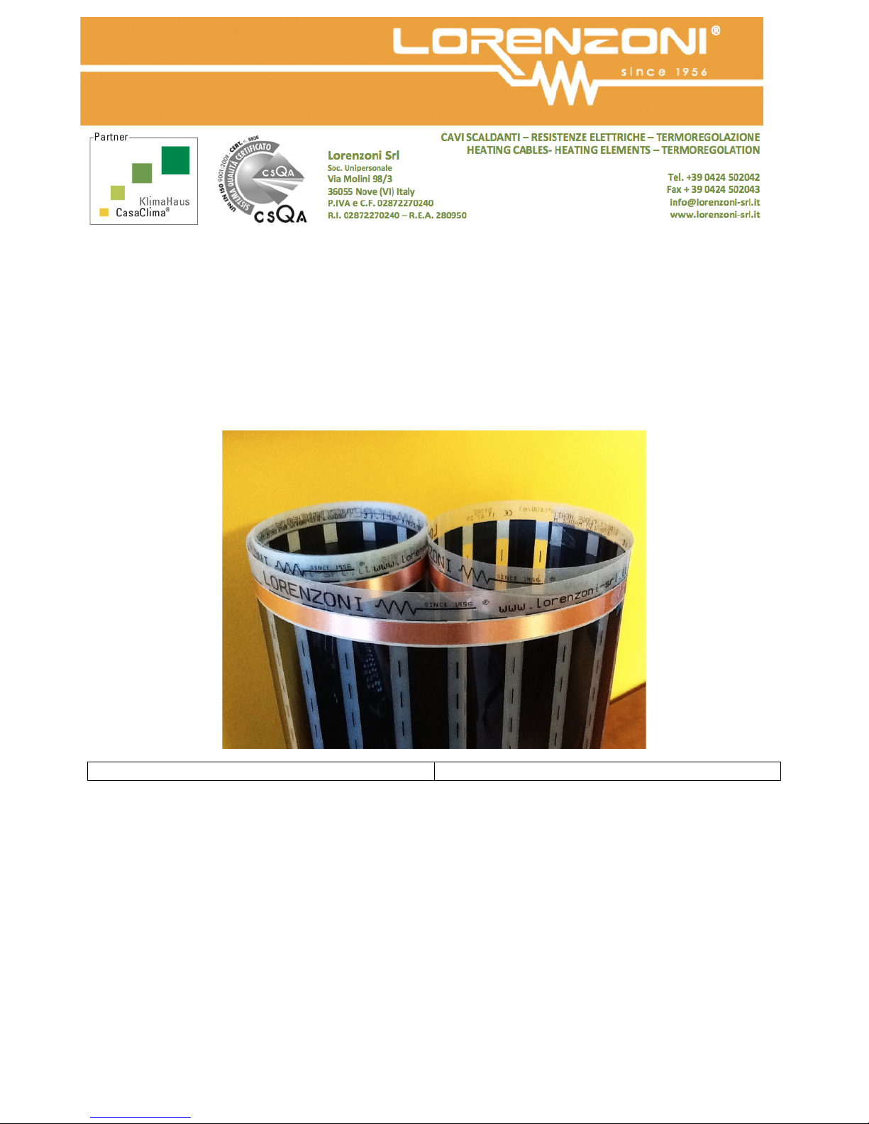
Lor Foil Kit 0.3
Installation instructions Lor Foil Kit 0.3 100 W
7