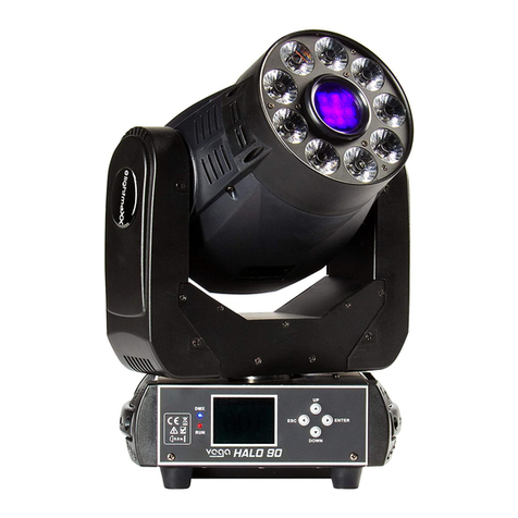
LOTRONIC SPOT10LED User manual

S
SP
PO
OT
T
L
LE
ED
D
M
MO
OV
VI
IN
NG
G
H
HE
EA
AD
D
L
LY
YR
RE
E
A
A
L
LE
ED
D
S
SP
PO
OT
T
S
SP
PO
OT
T
L
LE
ED
D
M
MO
OV
VI
IN
NG
G
H
HE
EA
AD
D
SPOT10LED (15-1930)
USER
MANUAL
MANUEL D’UTILISATION
BEDIENUNGSANLEITUNG
HANDLEIDING
IMPORTANT NOTE: Electric products must not be put into household waste. Please bring them to a recycling centre. Ask your local authorities or
your dealer about the way to proceed.
NOTE IMPORTANTE : Les produits électriques ne doivent pas être mis au rebut avec les ordures ménagères. Veuillez les faire recycler là où il existe
WICHTIGER HINWEIS: Elektrogeräte gehören nicht in den Hausmüll. Sie müssen in speziellen Betrieben recycelt werden. Bringen Sie sie zu einer
speziellen Entsorgungsstelle für Elektrokleingeräte (Wertstoffhof)!
BELANGRIJK: De elektrische producten mogen niet naast het huisvuil geplaatst worden. Gelieve deze te laten recycleren daar waar er centra’s
hiervoor voorzien is. Raadpleeg de plaatselijke autoriteiten of uw verkoper ivm de manier van recycleren.
Imported from China by LOTRONIC – Avenue Zénobe Gramme 1 – B-1480Saintes
©Copyright LOTRONIC 2015 SPOT10LED Page 1

1. BEFORE YOU BEGIN
Unpacking Instructions
Immediately upon receiving a fixture, carefully unpack the carton, check the contents to ensure that all parts are
present and have been received in good condition. Notify the freight company immediately and retain packing
material for inspection if any parts appear to be damaged from shipping or the carton itself shows signs of
mishandling. Keep the carton and all packing materials. In the event that a fixture must be returned to the factory, it
is important that the fixture be returned in the original factory box and packing.
Safety Instructions
Please read these instructions carefully, they include important information about the installation, usage and
maintenance of this product.
• Please keep this User Guide for future reference. If you sell the unit to another user, be sure that he also receives
this instruction booklet.
• Always make sure that you are connecting to the proper voltage, and that the line voltage you are connecting to is
not higher than that stated on the decal or rear panel of the fixture.
• This product is intended for indoor use only!
• To prevent risk of fire or shock, do not expose fixture to rain or moisture. Make sure there are no flammable
materials close to the unit while operating.
• The unit must be installed in a location with adequate ventilation, at least 20in (50cm) from adjacent surfaces. Be
sure that no ventilation slots are blocked.
• Always disconnect from power source before servicing or replacing fuse and be sure to replace with same fuse size
and type.
• Secure fixture to fastening device using a safety chain. Never carry the fixture solely by its head. Use its carrying
handles.
• Maximum ambient temperature (Ta) is 104° F (40°C). Do not operate the fixture at temperatures higher than this.
•In the event of a serious operating problem, stop using the unit immediately. Never try to repair the unit by
yourself. Repairs carried out by unskilled people can lead to damage or malfunction. Please contact the nearest
authorized technical assistance center. Always use the same type of spare parts.
• Don’t connect the device to a dimmer pack.
• Make sure the power cord is never crimped or damaged.
• Never disconnect the power cord by pulling or tugging on the cord.
• Avoid direct eye exposure to the light source while it is on.
GB
©Copyright LOTRONIC 2015 SPOT10LED Page 2

SPECIFICATIONS
Voltage: ..............................................................................................................110-240Vac/ 50-60Hz
Power consumption: ..........................................................................................................................................22W
Light source: ................................................................................................................1led of 10W White
Color : ..................................................................................................................7 color + white
Gobos : .............................................................................................................................7 fixed
Pan: ...................................................................................................................................... 540°
Tilt: ....................................................................................................................................... 190°
Angle: ..................................................................................................................................... 13°
Brightness : ....................................................................................................... 1500 Lux (@3m)
Function: ..........................................Sound
control, Auto-run, Master/Slave, DMX
512, Strobe
Channel: ..................................................................................................... 4/ 12 DMX channels
Data input.................................................................................... Locking 3-pin XLR male socket
Data output ............................................................................ Locking 3-pin DMX female socket
Data pin configuration ................................................................. Pin1 shield, pin 2 (-), pin 3 (+)
Dimensions.........................................................................................................290x170x16mm
N.W: ................................................................................................................................... 2.5kg
SETUP
Fuse Replacement
With a flat head screwdriver wedge the fuse holder out of its housing.
Remove the damaged fuse from its holder and replace with exactly the same type of fuse.
Insert the fuse holder back in its place and reconnect power.
The fuse is located inside this compartment. Remove using a flat head screwdriver.
Fixture Linking
You will need a serial data link to run light shows of one or more fixtures using a DMX-512 controller or to run
synchronized shows on two or more fixtures set to a master/slave operating mode. The combined number of
channels required by all fixtures on a serial data link determines the number of fixtures that the data link can
support.
Important: Fixtures on a serial/data link must be daisy chained in one single line. Maximum recommended serial
data link distance: 500 meters (1640 ft.) Maximum recommended number of fixtures on a serial data link: 32 fixtures
Data Cabling
To link fixtures together you must use data cables. If you choose to create your own cable, please use data-grade
cables that can carry a high quality signal and are less prone to electromagnetic interference.
CABLE CONNECTORS
Cabling must have a male XLR connector on one end and a female XLR connector on the other end.
DMX connector configuration
Termination reduces signal errors. To avoid signal transmission problems and interference, it is always advisable to
connect a DMX signal terminator.
INPUT
COMMON
DMX +
DMX-
Resistance 120 ohm
1/ 4w between pin 2
(DMX-) and pin 3
(DMX+) of the last
fixture.
©Copyright LOTRONIC 2015 SPOT10LED Page 3

CAUTION
Do not allow contact between the common and the fixture’s chassis ground. Grounding the common can cause a
ground loop, and your fixture may perform erratically. Test cables with an ohm meter to check correct polarity and
to make sure the pins are not grounded or shorted to the shield or each other.
3-PIN TO 5-PIN CONVERSION CHART
Note! If you use a controller with a 5-pin DMX output connector, you will need to use a 5-pin to 3-pin adapter.
The chart below details a proper cable conversion:
3 PIN TO 5 PIN CONVERSION CHART
Conductor 3 Pin Female (output) 5 Pin Male (Input)
Ground/Shield Pin 1 Pin1
Data (-) signal Pin 2 Pin 2
Data (+) signal Pin 3 Pin 3
Do not use Do not use
Setting up a DMX Serial Data Link
1. Connect the (male) 3 pin connector side of the DMX cable to the output (female) 3 pin connector of the controller.
2. Connect the end of the cable coming from the controller which will have a (female) 3 pin connector to the input
connector of the next fixture consisting of a (male) 3 pin connector.
3. Then, proceed to connect from the output as stated above to the input of the following fixture and so on.
Master/Slave Fixture Linking
1. Connect the (male) 3 pin connecter side of the DMX cable to the output (female) 3 pin connecter of the first
fixture.
2. Connect the end of the cable coming from the first fixture which will have a (female) 3 pin connecter to the input
connecter of the next fixture consisting of a (male) 3 pin connecter. Then, proceed to connect from the output as
stated above to the input of the following fixture and so on
3. Go to the menu of the first SPOT10LED and select RUN menu. Choose Master mode then select one of 8 auto
program or sound mode. on the others moving head, go to Run mode, select slave then adjust DMX address a 001.
Often, the set up for Master-Slave and Stand-alone operation requires that the first fixture in the chain be initialized
for this purpose via either settings in the control panel or DIP-switches. Secondarily, the fixtures that follow may also
require a slave setting. Please consult the '' Operating Instructions» section in this manual for complete instructions
for this type of setup and configuration.
©Copyright LOTRONIC 2015 SPOT10LED Page 4

OPERATING INSTRUCTIONS
Navigation through the Control Panel
Access control panel functions using the four panel buttons located directly underneath the LCD Display.
Button
Function
<MENU>
Used to access the menu or to return to a previous menu option
<UP>
<DOWN>
Scrolls through menu options in ascending order
Scrolls through menu options in descending order
<ENTER>
Used to select and store the current menu or option within a menu
When a menu function is selected, the display will show immediately the first available option for the selected menu
function. To select a menu item, press <ENTER>.
MENU MAP
DMX address setting
With this function, you can adjust the desired DMX-address via the Control Board.
-Select via the control board.
-Select Addr menu then adjust the DMX address by using up and down buttons. After, press enter button to
validate your setup.
-Press the Mode/Esc-button in order return to the main menu.
DMX Mode
This LED moving head can operate in 4 DMX channels or 12 DMX channels
-Select via the control board.
-Select Chmd menu and select 4CH or 12CH. After, press enter button to validate your setup.
-See description of DMX table later
Run Mode
In the【Run】mode,you can chose【Master】mode and【Slave】mode.
Auto Play
With this function, you can run one of the 8 Inside program with master mode.
-Select via the control board.
-Select SHMd menu select one programs ( 001 to 008 ) in using Up and Down buttons. After, press enter
button to start the program.
-Press the Mode/Esc-button in order return to the main menu.
Sound mode
With this function, you can run the moving head by sound-controlled.
-Select via the control board.
-Select Soun menu and select Yes to enter in sound mode or No to stay in auto mode. After, press enter
button to validate your setup.
-Press the Mode/Esc-button in order return to the main menu
©Copyright LOTRONIC 2015 SPOT10LED Page 5

Pan Reverse
With this function you can reverse the Pan-movement.
-Select via the control board.
-Select Pan menu and select Yes to reverse Pan or No to stay in normal mode. After, press enter button to
validate your setup.
-Press the Mode/Esc-button in order return to the main menu
Tilt Reverse
With this function you can reverse the Tilt -movement.
-Select via the control board.
-Select Tilt menu and select Yes to reverse Tilt or No to stay in normal mode. After, press enter button to
validate your setup.
-Press the Mode/Esc-button in order return to the main menu
Display Reverse
With this function you can reverse the display-movement.
-Select via the control board.
-Select Disp menu and select Yes to reverse display or No to stay in normal mode. After, press enter button to
validate your setup.
-Press the Mode/Esc-button in order return to the main menu
Reset Default
With this function, you can select restore factory set for ON or OFF, the default is OFF.
Reset Motor
-Select via the control board.
-Select Rst and press enter button to reset motor position
SLAVE MODE
Up-to 32 units can be daisy chained together with one single unit acting as Master and all other linked units acting as
Slaves. Slave units will all run in sync with the master unit without the need for an additional controller. Connections
can be made using standard DMX control cables with Master unit running in Auto Run or Sound Activated Modes
and placed at the beginning of the chain
Selection of Slave Mode
Press the “MENU” button and choose “RUN”. When the “ENTER” button is pressed, the LED display changes to
“SLAVE” and the unit will be slaved to control signals coming from a Master unit
©Copyright LOTRONIC 2015 SPOT10LED Page 6

DMX TABLE
4 DMX CHANNEL MODE
CHANNELS
FUNCTION
DMX
Functions
1
Pan
000-255
0-540
2
Tilt
000-255
0-190
3 Gobo and colors
wheels auto play
000-007
008-047
048-087
088-127
128-167
168-207
208-247
248-255
No function
Color change
Gobo change + gobo shake
Gobo and color change
Rotation of color wheel and gobo wheel
Gobo and color change + strobe
Rotation of color wheel and gobo wheel + strobe
Color and gobo sound control
4 Pan and tilt auto
play
000-007
008-032
033-058
059-084
085-110
111-136
137-162
163-188
189-239
240-255
No function
Pan / tilt move run 1
Pan / tilt move run 2
Pan / tilt move run 3
Pan / tilt move run 4
Pan / tilt move run 5
Pan / tilt move run 6
Pan / tilt move run 7
Pan / tilt move run 8
Pan / Tilt sound control
12 DMX CHANNEL MODE
CHANNELS
FUNCTION
DMX
Functions
1
Pan
000-255
0-540
2
Pan fine
000-255
Pan fine
3
Tilt
000-255
0-190
4
Tilt fine
000-255
Tilt fine
5
Pan & Tilt speed
000-255
Slow-fast
6
Dimmer
000-255
From dark to bright
7 Strobe
000-009
010-250
251-255
Shutter closed
Strobe ( from slow to fast )
Shutter open
8 Color wheel
000-023
024-047
048-071
072-095
096-119
120-143
144-167
148-191
192-255
Open ( white )
Color 1
Color 2
Color 3
Color 4
Color 5
Color 6
Color 7
Rainbow effect ( from slow to fast )
9 Gobo wheel
000-011
012-023
024-035
036-047
048-059
060-071
072-083
084-095
Open
Gobo 1
Gobo 2
Gobo 3
Gobo 4
Gobo 5
Gobo 6
Gobo 7
©Copyright LOTRONIC 2015 SPOT10LED Page 7

096-111
112-127
128-143
144-159
160-175
176-191
192-255
Gobo shake 1 ( from slow to fast )
Gobo shake 2 ( from slow to fast )
Gobo shake 3 ( from slow to fast )
Gobo shake 4 ( from slow to fast )
Gobo shake 5 ( from slow to fast )
Gobo shake 6 ( from slow to fast )
Gobo auto change ( from slow to fast )
10 Gobo and colors
wheels auto play
000-007
008-047
048-087
088-127
128-167
168-207
208-247
248-255
No function
Color change
Gobo change + gobo shake
Gobo and color change
Rotation of color wheel and gobo wheel
Gobo and color change + strobe
Rotation of color wheel and gobo wheel + strobe
Color and gobo sound control
11 Pan and tilt auto
play
000-007
008-032
033-058
059-084
085-110
111-136
137-162
163-188
189-239
240-255
No function
Pan / tilt move run 1
Pan / tilt move run 2
Pan / tilt move run 3
Pan / tilt move run 4
Pan / tilt move run 5
Pan / tilt move run 6
Pan / tilt move run 7
Pan / tilt move run 8
Pan / Tilt sound control
12
Reset
000-255
reset
(
200 stop 10 second = reset
)
©Copyright LOTRONIC 2015 SPOT10LED Page 8

PREPARATIFS
Déballage
Dès réception de l’appareil, ouvrez le carton et vérifiez que le contenu est complet et en bon état. Sinon, prévenez
immédiatement le transporteur et conservez l’emballage s’il montre des signes de mauvais traitements. Conservez le
carton et tous les matériaux d’emballage afin de pouvoir transporter l’appareil en toute sécurité.
Consignes de sécurité
Lisez attentivement ce manuel qui contient des informations importantes sur l’installation, l’utilisation et l’entretien
de cet appareil.
• Conservez le manuel pour référence ultérieure. Si l’appareil change un jour de propriétaire, assurez-vous que le
nouvel utilisateur est en possession du manuel.
• Assurez-vous que la tension secteur convient à cet appareil et qu’elle ne dépasse pas la tension d’alimentation
indiqué sur la plaque signalétique de l’appareil.
• Uniquement pour utilisation à l’intérieur!
• Afin d’éviter tout risque d’incendie ou de choc électrique, ne pas exposer cet appareil à la pluie ou à l’humidité.
Assurez-vous qu’aucun objet inflammable ne se trouve à proximité de l’appareil pendant son fonctionnement.
• Installez l’appareil à un endroit bien ventilé à une distance minimum de 50cm de toute surface. Assurez-vous que
les fentes de ventilation ne sont pas bloquées.
• Débranchez l’appareil du secteur avant toute manipulation ou entretien. Lorsque vous remplacez le fusible, utilisez
uniquement un fusible qui présente exactement les mêmes caractéristiques que l’ancien.
• Sécurisez l’appareil sur le dispositif de fixation au moyen d’une chaîne. Ne portez jamais l’appareil en le tenant par
le boîtier. Tenez-le par l’étrier.
• La température ambiante ne doit pas dépasser 40°C. Ne pas faire fonctionner l’appareil à des températures
supérieures.
• En cas de dysfonctionnement, arrêtez immédiatement l’appareil. N’essayez jamais de réparer l’appareil par vous-
même. Une réparation mal faite peut entraîner des dommages et des dysfonctionnements. Contactez un service
technique agréé. Utilisez uniquement des pièces détachées identiques aux pièces d’origine.
• Ne pas brancher l’appareil sur un variateur.
• Assurez-vous que le cordon d’alimentation n’est jamais écrasé ni endommagé.
• Ne jamais débrancher l’appareil en tirant sur le cordon.
• Ne pas exposer vos yeux à la source lumineuse.
F
©Copyright LOTRONIC 2015 SPOT10LED Page 9

CARACTERISTIQUES
Alimentation: ..........................................................................................................110-240Vac/ 50-60Hz
Consommation: ....................................................................................................................................................22W
Led: ...............................................................................................................................1led de 10W White
Couleurs : ............................................................................................................7 color + white
Gobos : ......................................................................................................................................7
Pan: ...................................................................................................................................... 540°
Tilt: ....................................................................................................................................... 190°
Angle: ..................................................................................................................................... 13°
Luminosité : ...........................................................................................................1500 ( @3m )
Fonction: ................................................................... musical
, Auto, Maîttre-esclave, DMX
512
Canaux DMX ......................................................................................................... 4 / 12 canaux
Entrée DMX : ................................................................................................DMX male 3 pattes
Sortie DMX : .............................................................................................DMX femelle 3 pattes
Branchement connecteur ................................................ Patte 1 masse,Patte 2 (-), patte 3 (+)
Dimensions :.....................................................................................................290x170x160mm
Poids :................................................................................................................................. 2.5kg
INSTALLATION
Débranchez le cordon d’alimentation avant de remplacer le fusible et utilisez toujours un fusible ayant les mêmes
caractéristiques que l’ancien.
Remplacement du fusible
Sortez le porte-fusible de son logement à l’aide d’un tournevis à lame plate.
Sortez le fusible grillé et remplacez-le par un autre en tous points identiques.
Remettez le porte-fusible dans son logement et rebranchez l’appareil sur le secteur.
Le fusible se trouve à l’intérieur de ce compartiment.
Retirez-le au moyen d’un tournevis à lame plate.
Branchement de plusieurs effets
Vous avez besoin d’un câble de données sériel pour faire fonctionner plusieurs effets au moyen d’une commande
DMX512 ou pour faire fonctionner deux ou plusieurs effets en mode maître/esclave. Le nombre combiné de canaux
requis par l’ensemble des appareils sur un câble de données sériel définit le nombre d’appareils que le câble de
données peut supporter.
Important: Les appareils doivent être branchés en série sur une seule ligne. Pour être conforme à la norme EIA-485 il
ne faut pas brancher plus de 32 appareils sur une ligne. Si plus de 32 appareils sont branchés sur une seule ligne de
données série sans répartiteur DMX à isolation optique, le signal numérique DMX risque d’être détérioré.
La distance maximale recommandée est de 500m. Le nombre maximum d’appareils branchés sur une liaison de
données est de 32.
Câblage
Pour relier des appareils ensemble, vous devez utiliser des câbles de transmission de données. Vous pouvez acheter
des câbles DMX certifiés directement chez un revendeur/distributeur ou construire vos propres câbles. Si vous
souhaitez fabriquer le câble vous-même, utilisez des câbles de données faible capacitance de haute qualité qui sont
moins sujets à des interférences électromagnétiques.
©Copyright LOTRONIC 2015 SPOT10LED Page 10

CONNECTEURS DE CABLE
Le câble doit posséder une fiche XLR mâle d’un côté et XLR femelle de l’autre. .
Configuration des connecteurs DMX
La résistance de fin de ligne réduit les erreurs de signal. Pour éviter des problèmes de transmission des signaux, il est
toujours conseillé de brancher une résistance de fin de ligne DMX.
ATTENTION
Il ne doit y avoir aucun contact entre le commun et la masse du châssis de l’appareil. La mise à la masse du commun
peut provoquer une boucle de masse et votre appareil fonctionne d’une façon étrange. Testez les câbles à l’aide d’un
ohm-mètre afin de vérifier la polarité et de vous assurer que les broches ne sont pas connectées à la masse ni court-
circuitées sur le blindage ou mutuellement.
CHARTE DE CONVERSION 3-PIN EN 5-PIN
Attention! Si vous utilisez un contrôleur muni d’une fiche de sortie DMX à 5 broches, vous devez utiliser un
adaptateur 5 broches en 3 broches.
La charte ci-dessous montre une conversion correcte:
CHARTE DE CONVERSION 3 PIN EN 5 PIN
Conducteur 3 Pin Femelle (sortie) 5 Pin Mâle (entrée)
Masse/blindage Pin 1 Pin1
Signal données (-) Pin 2 Pin 2
Signal données (+) Pin 3 Pin 3
Ne pas utiliser Ne pas utiliser
Mise en place d’une ligne de données DMX en série
1. Connectez le côté (mâle) à 3 broches du câble DMX sur la sortie (femelle) à 3 broches de la commande.
2. Connectez l’extrémité du câble provenant du contrôleur qui aura une fiche femelle à 3 broches, sur la fiche
d’entrée de l’appareil suivant qui est un connecteur mâle à 3 broches
3. Ensuite, branchez la sortie comme indiqué ci-dessus sur l’entrée de l’appareil suivant, etc.
Branchement Maître/Esclave
1. Connectez le côté mâle à 3 broches du cordon DMX sur la sortie (femelle) à 3 broches du premier appareil.
2. Connectez l’extrémité du cordon provenant du premier appareil (fiche femelle à 3 broches) sur l’entrée de
l’appareil suivant (fiche mâle à 3 broches). Branchez ensuite la sortie de l’appareil sur l’entrée de l’appareil suivant,
etc.
3. Réglez la lyre maître en mode maitre ( menu Run / master ) puis sélectionnez un programme auto ou le mode
musicale. Réglez les lyres esclaves en mode esclave ( menu Run / slave ) et sélectionnez l’adresse DMX 001
Le réglage pour un fonctionnement en maître/esclave ou autonome requiert souvent une initialisation du premier
appareil de la chaîne soit par un paramétrage du panneau de contrôle, soit par des commutateurs DIP. Par ailleurs,
les appareils peuvent également nécessiter un paramétrage en esclave. Veuillez consulter les instructions d’emploi
dans ce manuel pour avoir des instructions complètes pour ce type d’installation et de configuration.
ENTREE
COMMUN
DMX +
DMX-
Résistance de 120 Ω
1/ 4w entre pin 2
(DMX-) et pin 3
(DMX+) sur le dernier
appareil
©Copyright LOTRONIC 2015 SPOT10LED Page 11

Montage
Vous pouvez installer cet appareil dans n’importe quelle position pourvu qu’il y ait une ventilation suffisante.
FONCTIONNEMENT
Tableau de commande
Accédez aux fonctions du tableau de commande au moyen des quatre boutons qui se trouvent juste en-dessous de
l’écran LCD.
Bouton
Fonction
<MENU>
Accès au menu ou retour vers une option
précédente du menu
<UP>
<DOWN>
Défilement des options du menu dans un
ordre croissant ou décroissant
<ENTER>
Sélection et enregistrement du menu ou de
l’option dans un menu
Appuyez à plusieurs reprises sur <MENU> jusqu’à ce que vous atteigniez la fonction désirée. Utilisez les boutons
<UP> et <DOWN> pour naviguer dans les options du menu. Appuyez sur la touche <ENTER> pour sélectionner la
fonction en cours d’affichage ou pour activer une option dans le menu. Pour revenir sur l’option ou le menu
précédent sans changer la valeur, appuyez sur la touche <MENU>.
MENU
Adressage DMX
Avec cette fonction, vous pouvez régler l’adresse DMX.
- Sélectionnez le menu Adr puis ajuster l'adresse DMX en utilisant boutons Up et Down. Après, appuyez sur la touche
Enter pour valider votre configuration.
- Appuyez sur le bouton Esc pour revenir au menu principal.
Mode DMX ( ChMd )
Cette lyre peut fonctionner en 4 canaux DMX ou 12 canaux DMX
- Sélectionnez le menu et sélectionnez ChMd 4CH ou 12ch. Après, appuyez sur la touche Enter pour valider votre
configuration.
©Copyright LOTRONIC 2015 SPOT10LED Page 12

- Appuyez sur le bouton Esc pour revenir au menu principal.
- Voir la description de la table DMX plus tard
Mode Run ( SLMd )
En mode Run, vous pouvez choisir de configurer votre lyre soit en mode Maître soit en mode esclave.
Programme auto ( SHMd )
Avec cette fonction, vous pouvez exécuter l'un des huit programme interne en le mode maître.
- Sélectionnez le menu SHMd, sélectionnez une programmes (001-008) en utilisant les boutons Up et Down. Après,
appuyez sur la touche Enter pour lancer le programme.
- Appuyez sur le bouton Esc pour revenir au menu principal.
Mode auto ( Soun )
Avec cette fonction, vous pouvez Faire fonctionner la lyre au rythme de la musique
- Sélectionnez le menu Soun et sélectionnez On pour entrer en mode sonore ou Off pour rester en mode
automatique. Après, appuyez sur la touche Enter pour valider votre configuration.
- Appuyez sur le bouton Esc pour revenir au menu principal.
Pan inverse ( Pan )
Avec cette fonction, vous pouvez inverser le mouvement Pan.
- Sélectionnez le menu Pan et sélectionnez On pour inverser le Pan ou Off pour rester en mode normal. Après,
appuyez sur la touche Enter pour valider votre configuration.
- Appuyez sur le bouton Esc pour revenir au menu principal.
Tilt inverse ( TIL )
Avec cette fonction, vous pouvez inverser le mouvement tilt.
- Sélectionnez le menu TIL et sélectionnez On pour inverser le tilt ou Off pour rester en mode normal. Après, appuyez
sur la touche Enter pour valider votre configuration.
- Appuyez sur le bouton Esc pour revenir au menu principal.
Affichage inversé ( dISP )
Avec cette fonction, vous pouvez inverser le sens d’affichage
- Sélectionnez le menu Disp et sélectionnez On pour inverser l'affichage ou Off pour rester en mode normal. Après,
appuyez sur la touche Entrée pour valider votre configuration.
- Appuyez sur la / Esc-bouton Mode pour retourner au menu principal
Réglage usine ( rFAC )
Avec cette fonction, vous pouvez restaurer les réglage usine ( ON ou OFF ) la valeur par défaut est OFF.
Reset position moteur ( rST )
- Sélectionnez Rst et appuyez sur la touche Enter pour réinitialiser la position du moteur
©Copyright LOTRONIC 2015 SPOT10LED Page 13

MODE ESCLAVE
Jusqu’à 32 appareils peuvent être relies ensemble et un appareil agit comme Maître. Les Esclaves fonctionnent de la
même manière que le Maître. Reliez les appareils au moyen d’un cordon DMX. Le Maître peut fonctionner en mode
automatique ou active par le son et doit être place au début de la chaîne.
Sélection du mode Esclave
Appuyez sur “MENU” et sélectionnez “RUN”. Lorsque vous appuyez sur ENTER, l’afficheur indique « SLAVE » et
l’appareil obéit aux signaux qu’il reçoit du Maître.
MODES DMX
Réglage des addresses DMX
Appuyez sur “MENU” pour afficher “Addr”.Ensuite, réglez les adresses individuelles de « 001” à “512” au moyen des
touches “UP” et “DOWN”.
TABLEAU CANAUX DMX
MODE 4 CANAUX DMX
CANAL
FONCTION
DMX
DESCRIPTION
1
Pan
000-255
0-540°
2
Tilt
000-255
0-190°
3 Mode auto roues
couleurs et gobos
000-007
008-047
048-087
088-127
128-167
168-207
208-247
248-255
Pas de fonction
Changement couleur auto
Changement couleur auto + gobo shake
Changement couleurs et gobos auto
Rotation roues couleurs et gobos
Changement couleurs et gobos auto + strobe
Rotation roues couleurs et gobos + stobe
Contrôle roues couleurs et gobo en mode musical
4 Mode auto
Pan / Tilt
000-007
008-032
033-058
059-084
085-110
111-136
137-162
163-188
189-239
240-255
Pas de fonction
Mouvement 1 Pan / Tilt
Mouvement 2 Pan / Tilt
Mouvement 3 Pan / Tilt
Mouvement 4 Pan / Tilt
Mouvement 5 Pan / Tilt
Mouvement 6 Pan / Tilt
Mouvement 7 Pan / Tilt
Mouvement 8 Pan / Tilt
Mouvement Pan / Tilt en mode musical
12 DMX CHANNEL MODE
CANAL
FONCTION
DMX
DESCRITPION
1
Pan
000-255
0-540°
2
Pan fine
000-255
Pan fine
3
Tilt
000-255
0-190°
4
Tilt fine
000-255
Tilt fine
5
Vitesse Pan - tilt
000-255
De rapide à lent
6
Dimmer
000-255
De 0 à 100%
7 Strobe
000-009
010-250
Fermé
Strobe ( de lent à rapide )
©Copyright LOTRONIC 2015 SPOT10LED Page 14

251-255
Ouvert
8 Roue couleur
000-023
024-047
048-071
072-095
096-119
120-143
144-167
148-191
192-255
Ouvert ( white )
Color 1
Color 2
Color 3
Color 4
Color 5
Color 6
Color 7
Rainbow effect ( from slow to fast )
9 Roue gobo
000-011
012-023
024-035
036-047
048-059
060-071
072-083
084-095
096-111
112-127
128-143
144-159
160-175
176-191
192-255
Ouvert
Gobo 1
Gobo 2
Gobo 3
Gobo 4
Gobo 5
Gobo 6
Gobo 7
Gobo shake 1 ( de lent à rapide )
Gobo shake 2 ( de lent à rapide )
Gobo shake 3 ( de lent à rapide )
Gobo shake 4 ( de lent à rapide )
Gobo shake 5 ( de lent à rapide )
Gobo shake 6 ( de lent à rapide )
Défilement automatique gobo ( de lent à rapide )
10 Mode auto roues
couleurs et gobos
000-007
008-047
048-087
088-127
128-167
168-207
208-247
248-255
Pas de fonction
Changement couleur auto
Changement couleur auto + gobo shake
Changement couleurs et gobos auto
Rotation roues couleurs et gobos
Changement couleurs et gobos auto + strobe
Rotation roues couleurs et gobos + stobe
Contrôle roues couleurs et gobo en mode musical
11 Mode auto
Pan / Tilt
000-007
008-032
033-058
059-084
085-110
111-136
137-162
163-188
189-239
240-255
Pas de fonction
Mouvement 1 Pan / Tilt
Mouvement 2 Pan / Tilt
Mouvement 3 Pan / Tilt
Mouvement 4 Pan / Tilt
Mouvement 5 Pan / Tilt
Mouvement 6 Pan / Tilt
Mouvement 7 Pan / Tilt
Mouvement 8 Pan / Tilt
Mouvement Pan / Tilt en mode musical
12
Reset
000-255
reset
(
10s après la valeur 200 = reset
)
©Copyright LOTRONIC 2015 SPOT10LED Page 15

1. VORBEREITUNGEN
Auspacken
Sofort nach Empfang vorsichtig den Karton auspacken und den Inhalt überprüfen. Alle Teile müssen vollzählig und in
einwandfreiem Zustand sein. Sofort die Transportfirma benachrichtigen und das Verpackungsmaterial
aufbewahren, wenn Teile Transportschäden aufweisen. Verpackungsmaterial auch für späteren Transport des
Geräts aufbewahren.
Sicherheitshinweise
Diese Anleitung sorgfältig vor der ersten Inbetriebnahme lesen. Sie enthält wichtige Informationen über Installation,
Gebrauch und Instandhaltung des Geräts.
• Die Anleitung für spätere Bezugnahme aufbewahren und an den nächsten Bediener weitergeben.
• Stets die Netzspannung vor Anschluss des Geräts überprüfen Sie muss mit der auf der Rückseite des Geräts
angegebenen Spannung übereinstimmen und darf auf keinen Fall höher sein.
• Dieses Gerät ist nur für Innengebrauch!
• Um Brand und Stromschlag zu vermeiden, das Gerät vor Regen und Feuchtigkeit schützen. Keine brennbaren
Materialien während des Betriebs in der Nähe des Geräts lassen.
• Das Gerät muss an einem gut belüfteten Ort und in mindestens 50cm Entfernung zur nächsten Fläche angebracht
werden. Darauf achten, dass die Belüftungsschlitze nicht blockiert oder verstopft sind.
• Immer erst das Gerät vom Netz trennen, bevor es gewartet oder die Sicherung ersetzt wird. Die Sicherung nur
durch eine identische ersetzen.
• Das Gerät mit einer Sicherheitskette befestigen. Das Gerät niemals nur am Kopf tragen, sondern auch am Sockel.
• Die Raumtemperatur darf 40°C nicht überschreiten. Das Gerät niemals bei höheren Temperaturen betreiben.
• Bei Betriebsstörungen das Gerät sofort ausschalten. Das Gerät niemals selbst reparieren. Reparaturen dürfen nur
von einem Fachmann vorgenommen werden. Alle verwendeten Ersatzteile müssen mit den Originalteilen identisch
sein.
• Das Gerät nicht an ein Dimmerpack anschließen.
•Vergewissern Sie sich, dass das Netzkabel nicht zerquetscht oder beschädigt werden kann. Das Netzkabel dieses
Geräts kann nicht ausgewechselt werden. Falls es beschädigt ist, muss das Gerät entsorgt werden
• Beim Abziehen des Netzsteckers nur am Stecker ziehen, niemals am Kabel.
• Niemals direkt in die Lichtquelle blicken.
•Netztrennungsvorrichtungen
a) Wenn das Gerät über den Netzstecker ausgeschaltet wird, muss die Steckdose jederzeit leicht zugänglich
bleiben
b) Wenn das Gerät über einen Schalter ausgeschaltet wird, muss dieser klar gekennzeichnet und leicht zugänglich
sein.
TECHNISCHE DATEN
Versorgung: .............................................................................................110-240Vac/ 50-60Hz
Verbrauch: ........................................................................................................................... 22W
Lichtquelle: .................................................................................................... 1x 10W LED Weiss
Farben : .............................................................................................................7 Farben + weiß
Gobos : .............................................................................................................................7 feste
Pan: ...................................................................................................................................... 540°
Tilt: ...................................................................................................................................... 190°
Winkel: .................................................................................................................................. 13°
©Copyright LOTRONIC 2015 SPOT10LED Page 16

Helligkeit : ........................................................................................................ 1500 Lux (@3m)
Betriebsarten: ....................Musiksteuerung, Automatik, Master/Slave, DMX512, Stroboskop
Kanäle: ............................................................................................................4/ 12 DMX Kanäle
Dateneingang ............................................................................................. 3-pol. XLR Verbinder
Datenausgang ............................................................................................ 3-pol. XLR Verbinder
Stiftbelegung ...........................................................................Stift1 Masse, Stift 2 (-), Stift 3 (+)
Abmessungen.....................................................................................................290x170x16mm
Nettogewicht: .................................................................................................................... 2.5kg
AUFBAU
Auswechseln der Sicherung
Mit einem flachen Schraubendreher den Sicherungshalter aus seinem Gehäuse entfernen.
Die durchgebrannte Sicherung aus dem Halter nehmen und durch eine identische Sicherung
ersetzen.
Den Sicherungshalter zurück ins Gehäuse setzen und Netz wieder anschließen.
Die Sicherung befindet sich im Inneren dieses Fachs. Mit einem flachen Schraubendreher entfernen.
Hintereinanderschalten mehrerer Geräte
Wenn mehrere Geräte über einen DMX Controller gesteuert werden oder zwei und mehr Geräte im Master/Slave
Betrieb arbeiten sollen, wird ein serielles Datenkabel benötigt. Die kombinierte Anzahl von Kanälen, die von allen
Geräten in einer seriellen Datenverbindung benötigt werden, bestimmt die Anzahl von Geräten, die die
Datenverbindung unterstützen kann.
Wichtig: Die empfohlene Höchstlänge einer seriellen Datenverbindung beträgt 500m. Die empfohlene Höchstmenge
an Geräten in einer seriellen Datenverbindung beträgt 32.
Verkabelung
Für den Anschluss der Geräte muss spezielles Datenkabel verwendet werden. Wenn Sie Ihr Kabel selbst herstellen
möchten, benutzen Sie bitte Datenkabel, dass eine hochwertige Signalübertragung gewährleistet und weniger
anfällig für elektromagnetische Störfelder ist.
KABELVERBINDER
Die Kabel müssen einen XLR Stecker auf der einen und eine XLR Buchse auf der anderen Seite besitzen.
DMX Steckerbelegung
Der Endwiderstand verringert Signalfehler. Um Signalübertragungsprobleme und Störungen zu vermeiden, ist es
ratsam, einen DMX Signalwiderstand zwischenzuschalten.
3-PIN AUF 5-PIN UMSETZTABELLE
Hinweis! Wenn Sie ein Steuerpult mit 5-pol. DMX Ausgangsverbinder benutzen, müssen Sie einen 5- auf 3-pol.
Adapter benutzen.
In der nachstehenden Tabelle steht die richtige Kabelumsetzung:
EINGANG
NEUTRAL
DMX +
DMX-
120 Ohm 1/4W
Widerstand zwischen
Pin2 (DMX-) und Pin 3
(DMX+) am letzten
Gerät
©Copyright LOTRONIC 2015 SPOT10LED Page 17

Leiter 3 Pin Buchse (Ausgang) 5 Pin Stecker (Eingang)
Masse/Abschirmung Pin 1 Pin1
Datensignal (-) Pin 2 Pin 2
Datensignal (+) Pin 3 Pin 3
Nicht benutzen Nicht benutzen
Einrichten einer seriellen DMX Datenverbindung
1. Den 3-pol. Stecker des DMX Kabels in die 3-pol. Eingangsbuchse des Controllers stecken.
2. Das vom Controller kommende Kabel mit der 3-pol. Buchse an den 3-pol. Eingangsstecker des folgenden Geräts
stecken.
3. Dann den Ausgang des Geräts an den Eingang des folgenden Geräts anschließen usw.
Master/Slave Anschluss
1. Den 3-pol. Stecker des DMX Kabels in die 3-pol. Eingangsbuchse des ersten Geräts stecken.
2. Das vom ersten Gerät kommende Kabel mit der 3-pol. Buchse an den 3-pol. Eingangsstecker des folgenden Geräts
stecken. Dann den Ausgang des Geräts an den Eingang des folgenden Geräts anschließen usw.
3. Gehen Sie ins Menü des ersten SPOT10LED und wählen Sie das RUN Menü. Wählen Sie den MASTER Mode und
dann eines der 8 Automatikprogramme oder musikgesteuerten Betrieb. Für die anderen Moving Heads gehen Sie in
den RUN Mode, wählen Sie SLAVE und stellen Sie die DMX Adresse auf 001 ein.
BEDIENUNG
Beschreibung des Bedienfelds
Die Funktionen sind über die vier Tasten unterhalb des Displays zugänglich.
Taste
Funktion
<MODE/ESC>
Gibt Zugang zum Menü oder schaltet zurück zum vorigen Menü
<UP>
<DOWN>
Durchlauf durch die Optionen in aufsteigender oder rückläufiger Reihenfolge
<ENTER>
Zur Auswahl und Speicherung des laufenden Menüs oder der Option im Menü
Wenn eine Menüfunktion gewählt ist, erscheinen sofort die ersten möglichen Optionen der gewählten Funktion. Um
eine Einstellung zu wählen, auf ENTER drücken.
MENÜ
Einstellung der DMX Adresse
-Addr Menü wählen und die gewünschte DMX Adresse mit den UP und DOWN Tasten einstellen. Dann mit
ENTER bestätigen.
-Mode/Esc-Taste drücken, um ins Hauptmenü zurückzugehen.
DMX Betrieb
Das Moving Head kann mit 4 oder 12 DMX Kanälen arbeiten.
-Chmd Menü wählen und 4CH oder 12CH wählen. Mit ENTER bestätigen.
-Beschreibung der DMX Kanäle siehe DMX Tabelle
Run Betrieb
Im【Run】Betreib jaben Sie die Wahl zwischen【Master】und【Slave】Betrieb.
©Copyright LOTRONIC 2015 SPOT10LED Page 18

Auto Play
Mit dieser Funktion können Sie eins der 8 programmierten Programme im Master-Betrieb abspielen.
-Im SHMd Menü ein Programm ( 001 bis 008 ) mit den Up und Down Tasten wählen. Mit ENTER bestâtigen.
-Mode/Esc-Taste drücken, um ins Hauptmenü zurückzugehen.
Sound Betrieb
In dieser Betriebsart wird das Moving Head musikgesteuert.
-Soun Menü wählen und YES wählen, um in musikgesteuerten Betrieb zu schalten oder NO, um im
Automatikbetrieb zu bleiben. Mit ENTER bestätigen.
-Mode/Esc-Taste drücken, um ins Hauptmenü zurückzugehen.
Pan Reverse
Umkehrung der PAN Bewegung
-Pan Menü wählen und YES wählen, um die horizontale Bewegung umzukehren oder NO, um im normalen
Betrieb zu bleiben. Mit ENTER bestätigen.
-Mode/Esc-Taste drücken, um ins Hauptmenü zurückzugehen.
Tilt Reverse
Umkehrung der TILT Bewegung
-Tilt Menü wählen und YES wählen, um die vertikale Bewegung umzukehren oder NO, um im normalen
Betrieb zu bleiben. Mit ENTER bestätigen.
-Mode/Esc-Taste drücken, um ins Hauptmenü zurückzugehen.
Display Reverse
Umkehrung des Displays
-Disp Menü wählen und YES wählen, um die Displayanzeige umzukehren oder NO, um im normalen Betrieb zu
bleiben. Mit ENTER bestätigen.
-Mode/Esc-Taste drücken, um ins Hauptmenü zurückzugehen.
Reset auf Werkseinstellungen
Auf ON stellen, alle Werte auf die Werkseinstellungen zurückzusetzen. Werkseinstellung ist OFF.
Motor Reset
-Rst wählen und ENTER drücken, um die Motorstellung zu resetten.
SLAVE MODE
Bis zu 32 Geräte können aneinandergeschlossen werden und wie ein einziges Gerät arbeiten. Ein Gerät ist der
Master und alle anderen Geräte sind Slaves und führen genau dieselben Bewegungen aus wie das Mastergerät.
Hierfür wird kein zusätzlicher Controller benötigt. Die Anschlüsse erfolgen über Standard XLR Kabel. Das Mastergerät
muss auf AUTO Run oder musikgesteuerten Betrieb eingestellt sein und am Anfang der Kette stehen.
Einstellung des Slave Betriebs
“MENU” Taste drücken und “RUN” wählen. Wenn die “ENTER” Taste gedrückt wird, erscheint “SLAVE” auf dem
Display und das Gerät befolgt die Steuersignale, die vom Master kommen.
DMX TABELLE
4 DMX KANALBETRIEB
©Copyright LOTRONIC 2015 SPOT10LED Page 19

KANÄLE
FUNKTION
DMX
Funktionen
1
Pan
000-255
0-540
2
Tilt
000-255
0-190
3 Gobo and colors
wheels auto play
000-007
008-047
048-087
088-127
128-167
168-207
208-247
248-255
No function
Color change
Gobo change + gobo shake
Gobo and color change
Rotation of color wheel and gobo wheel
Gobo and color change + strobe
Rotation of color wheel and gobo wheel + strobe
Color and gobo sound control
4 Pan and tilt auto
play
000-007
008-032
033-058
059-084
085-110
111-136
137-162
163-188
189-239
240-255
No function
Pan / tilt move run 1
Pan / tilt move run 2
Pan / tilt move run 3
Pan / tilt move run 4
Pan / tilt move run 5
Pan / tilt move run 6
Pan / tilt move run 7
Pan / tilt move run 8
Pan / Tilt sound control
12 DMX KANALBETRIEB
KANÄLE
FUNKTION
DMX
Funktionen
1
Pan
000-255
0-540
2
Pan fine
000-255
Pan fine
3
Tilt
000-255
0-190
4
Tilt fine
000-255
Tilt fine
5
Pan & Tilt speed
000-255
Slow-fast
6
Dimmer
000-255
From dark to bright
7 Strobe
000-009
010-250
251-255
Shutter closed
Strobe ( from slow to fast )
Shutter open
8 Color wheel
000-023
024-047
048-071
072-095
096-119
120-143
144-167
148-191
192-255
Open ( white )
Color 1
Color 2
Color 3
Color 4
Color 5
Color 6
Color 7
Rainbow effect ( from slow to fast )
9 Gobo wheel
000-011
012-023
024-035
036-047
048-059
060-071
072-083
084-095
096-111
112-127
128-143
144-159
Open
Gobo 1
Gobo 2
Gobo 3
Gobo 4
Gobo 5
Gobo 6
Gobo 7
Gobo shake 1 ( from slow to fast )
Gobo shake 2 ( from slow to fast )
Gobo shake 3 ( from slow to fast )
Gobo shake 4 ( from slow to fast )
©Copyright LOTRONIC 2015 SPOT10LED Page 20
This manual suits for next models
1
Table of contents
Languages:
Other LOTRONIC Dj Equipment manuals

LOTRONIC
LOTRONIC MY60-SPOT User manual

LOTRONIC
LOTRONIC AFX LIGHT LED PAR CAN 4x15W 5-in-1 User manual

LOTRONIC
LOTRONIC LAS1000RGB-5IN1 User manual

LOTRONIC
LOTRONIC AFX LIGHT SCAN1000FX5-RGB User manual

LOTRONIC
LOTRONIC AFX Light PARLED-118 User manual

LOTRONIC
LOTRONIC Party Light & Sound ARTY-MOBILE8-SET User manual