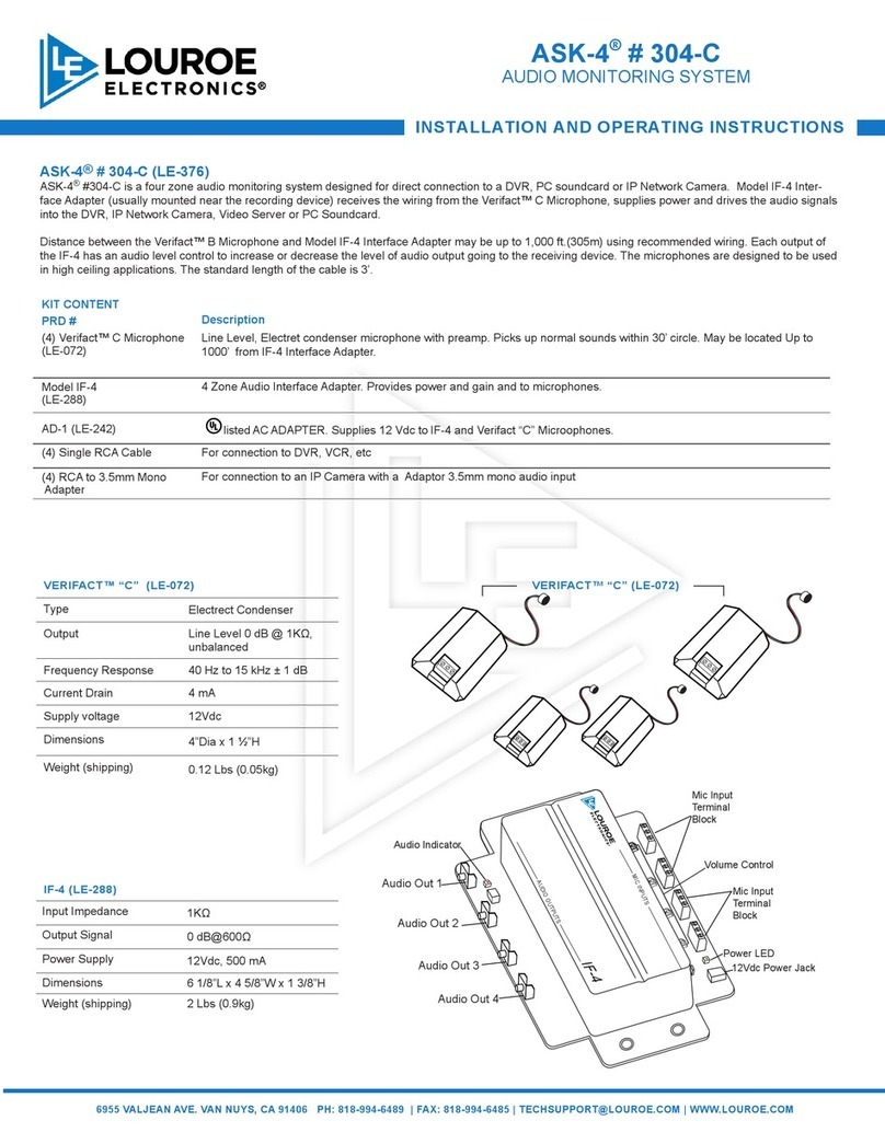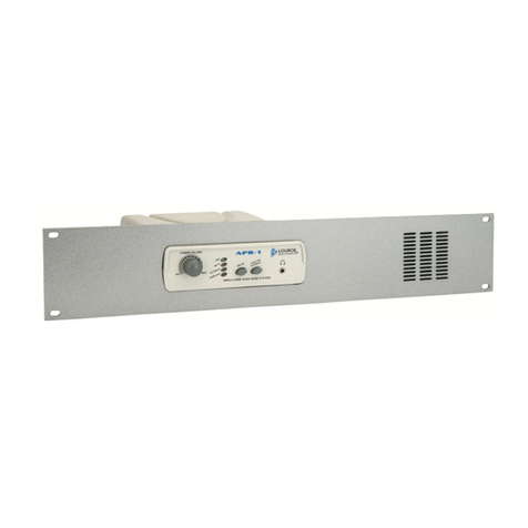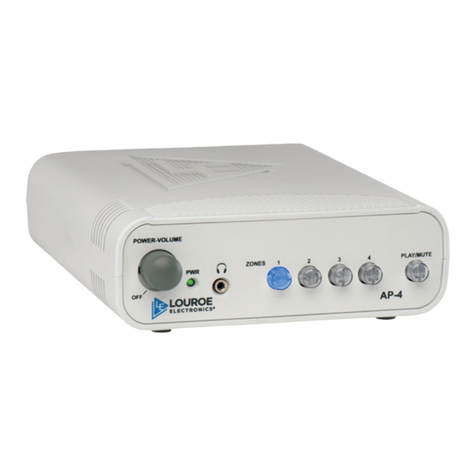
ASK-4®# 300
AUDIO MONITORING SYSTEM
INSTALLATION AND OPERATING INSTRUCTIONS
6955
V
ALJEAN
A
VE.
V
AN
NUYS,
CA
91406
PH:
818-994-6489
|
F
AX:
818-994-6485
|
[email protected] |
WWW
.LOUROE.COM
6955
V
ALJEAN
A
VE.
V
AN
NUYS,
CA
91406
PH:
818-994-6489
|
F
AX:
818-994-6485
|
[email protected] |
WWW
.LOUROE.COM
INSTALLATION INSTRUCTIONS
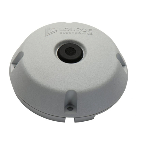
VERIFACT “A” MIC INSTALLATIONS INSTRUCTIONS
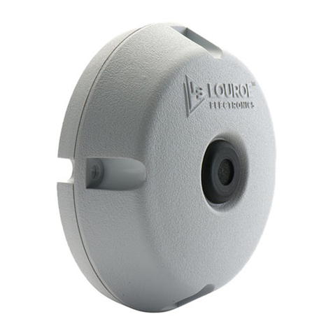
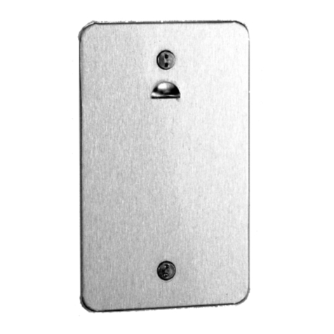
Model A Microphone is designed for surface mounting to a ceiling
or wall. Microphone will pick up sounds 15’ away from all directions.
For best results, install microphone as close to desired area of
coverage as possible. Avoid mounting microphone to ceiling heights
in excess of 10’, or near air vents, refrigeration units, or other audio
interferences.
NOTE: Make wiring connection on back side of microphone
before installing microphone to ceiling or at surface.
Located on back side of microphone is a terminal block marked A,
B and C. A is 12 Vdc, B is Audio, C is Ground (common)
1. Using recommended wiring, connect as follows: RED wire to
terminal A (12Vdc), BLACK wire to terminal B (Audio), BARE
wire to terminal C (Ground)
NOTE: If using wiring from other manufacturers, color
code may vary.
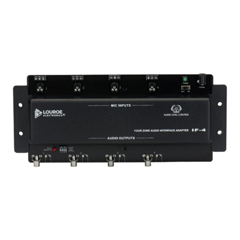
IF-1 INTERFACE ADAPTER INSTALLATIONS INSTRUCTIONS
The IF-1 Interface Adapter serves as an interface device between
the microphone and the audio receiver (DVR/VCR, PC Sound Card,
etc..). The IF-1 can be installed several ways:
1.Wall mounted close to DVR/VCR or IP Network Camera, etc
2.Attached to side of the receiving device using two-way ¼”
adhesive tape (not provided)
MICROPHONE CONNECTION TO IF-1 INTERFACE ADAPTER
Bring in other end of wiring from microphone and connect to “MIC
INPUT” terminal block on IF-1 marked, A, B and C. Connect as
follows:
Terminal A of microphone to terminal A of IF-1 12Vdc
Terminal B of microphone to terminal B of IF-1 Audio Output
Terminal C of microphone to terminal C of IF-1 Ground (common)
To apply power to the system, Model AD-1 12Vdc power supply is
included. First connect small end (female plug) into 12Vdc jack on
IF-1, then connect 2-prong power block to a standard 110Vac outlet
or power strip.
NOTE: IF-1 contains two types of audio outputs. A connection
cable is provided for each type.
1. RCA
2. 3.5mm stereo
3. RCA to 3.5mm mono with adaptor
These two audio outputs are in parallel ... only one can be used.
CHOOSE YOUR SETTING
DVR/VCR - RECORDING INSTRUCTIONS
CONNECTION BETWEEN IF-1 INTERFACE ADAPTER AND DVR/
VCR WITH RCA TYPE AUDIO CONNECTIONS
To make connection to DVR/VCR, plug the RCA cable (supplied)
into the RCA type audio output jack located on the output side of
Model IF-1. Connect other end of RCA cable to the DVR/VCR’s “AU-
DIO IN” jack
IP NETWORK CAMERA INSTRUCTIONS
CONNECTION BETWEEN IF-1 AND AN IP NETWORK CAMERA,
DVR, VIDEO SERVER WITH 3.5mm MONO TYPE AUDIO CON-
NECTIONS
To make connection to IP Network Camera, plug the RCA to 3.5mm
mono cable with adaptor (supplied) into the RCA audio out jack lo-
cated on the output side of IF-1, connect other end of cable (3.5mm)
to the camera’s audio in jack.
IP NETWORK, VIDEO SERVER, DVR, ETC... INSTRUCTIONS
CONNECTION BETWEEN IF-1 AND A DVR, IP NETWORK CAM-
ERA OR PC SOUNDCARD WITH 3.5mm STEREO TYPE CON-
NECTION.
To make connection, plug the 3.5mm stereo cable (supplied) into the
“audio out” jack located on the output side of IF-1. Plug the other end
of the cable to “AUDIO IN” of DVR, IP Network Camera or “ LINE IN”
of PC soundcard.
NOTE
SENSITIVITY SWITCH OF MICROPHONE
For special installations that require less microphone sensitiv-
ity, a sensitivity switch has been added to the microphone pre-
amp (PC board) and has two positions - N and L:
N represents normal sensitivity (0dB output into 1KΩ) L repre-
sents low sensitivity (-6dB output into 1 KΩ).
NOTE: Louroe™ Verifact microphones are always shipped with
the sensitivity switch in normal (N) position. Do not change un-
less required. To make an adjustment, use a small screwdriver
and move slide switch from N to L. Sensitivity switch is located
on the backside of Verifact™ A Microphone.
