6955
V
ALJEAN
A
VE.
V
AN
NUYS,
CA
91406
PH:
818-994-6489
|
F
AX:
818-994-6485
|
[email protected] |
WWW
.LOUROE.COM
ASK-4®# 501
AUDIO MONITORING SYSTEM
INSTALLATION AND OPERATING INSTRUCTIONS
INSTALLATION INSTRUCTIONS
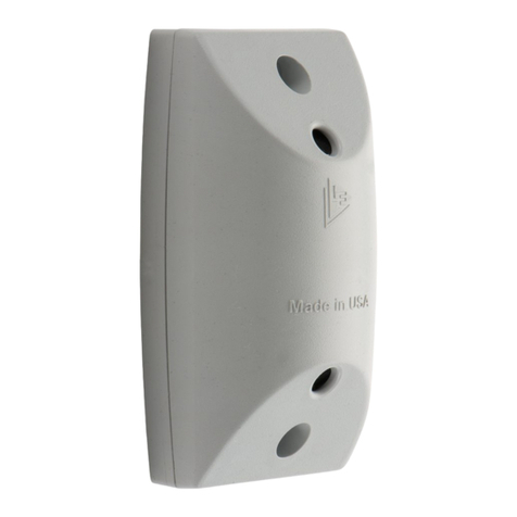
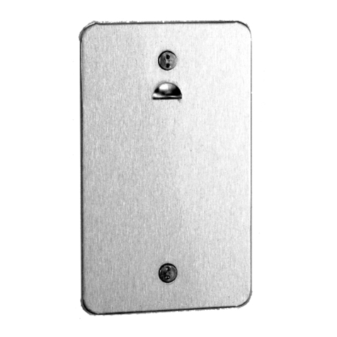
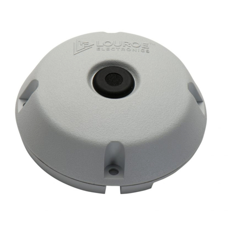
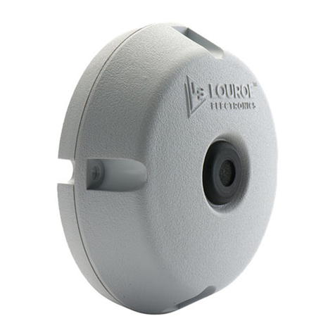
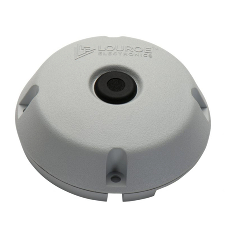
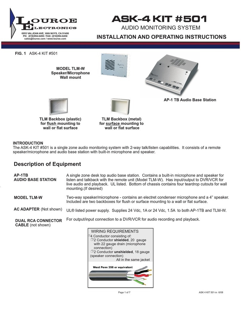
TLM-W SPEAKER/MICROPHONE
Model TLM-W is designed for mounting to a wall or at surface. In-
cluded is a plastic backbox for surface mounting to a wall. If ush
mounting is needed, a 3 gang electrical box (not supplied) maybe
used.
1. Drill an opening at top, bottom, side or back of backbox for passing wir-
ing or connecting conduit. Four small screws are supplied for attaching
backbox to a wall.
2. Four screws are also supplied for attaching the TLM faceplate to the
backbox. The plastic hole plugs must be place on the screw holes of
the faceplate to cover the screws.
WIRING CONNECTIONS BETWEEN MODEL TLM-W SPEAKER/MI-
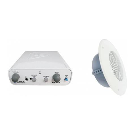
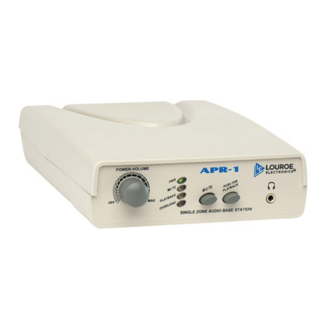
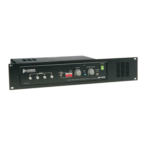
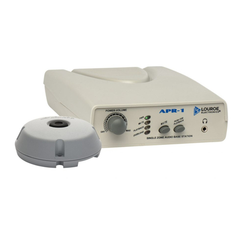
CROPHONE AND AP-1TB AUDIO BASE STATION
1. Connect one end of recommended cable to remote speaker/micro-
phone (TLM-W). Connect wires wrapped with overall shield to termi-
nals “A”, “B”, and “C” of TLM-W’s terminal block. When using sample
cable, connect red wire to terminal “A”; black wire to terminal “B” and
bare wire to terminal “C”.
2. Connect the two speaker wires (twisted pair) green and white to green
and white wires of TLM-W’s 70V transformer. Using wire nut connect
green wire to green wire of TLM-W’s 70V Transformer. Again, using
wire nut connect white wire to white wire of TLM-W’s 70V Transformer.
3. Connect the other end of the cable to AP-1TB Mic 6-Pin Terminal
Block [12]. Make sure that wire connected to terminal “A” of remote
TLM-W connects to terminal “A” of AP-1TB’s Mic 6-Pin Terminal Block
[12]; wire connected to terminal “B” of TLM-W connects to terminal “B”
of AP-1TB; “C” to “C”. Observe cable color coding. Terminal “P” of
AP-1TB is not used with this application. Used only when paralleling
to a second AP-1TB.
4. For speaker connection, connect green speaker wire (positive) to Mic
6-Pin Terminal Block [12] terminal “SP”, connect white speaker wire
(negative) to “G”.
5. When a recording device is used (DVR,VCR,etc.) connect Audio-OUT
Jack [11] to recorder’s Audio-IN Jack with the dual RCA cable (sup-
plied).
6. Connect Audio-IN Jack [10] to recorder’s Audio-OUT Jack with the re-
maining RCA plug.
OPERATION AND TEST
1. Applying Power To The System - With all wiring connections com-
plete, power up the system using the 12Vdc, 500mA power supply
included with the kit. First connect the small end of power supply to
the DC IN Jack [13] located on rear panel of AP-1TB Base Station.
Connect the large end with the 2-prong plug to a standard 120Vac wall
outlet or power strip.
2. Rotate the Power-Volume Control - [1] ON position as indicated by
the Power LED[3] Power LED [3] will illuminate.
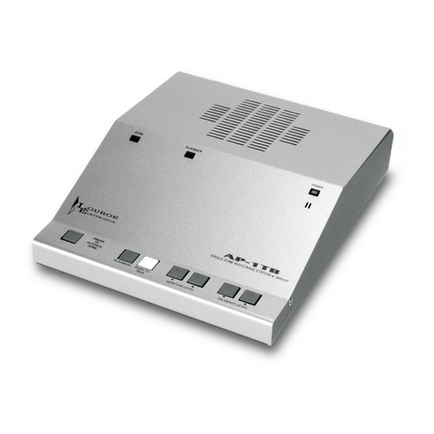
3. Testing For Listen And Talkback - At the AP-1TB Base Station push
in Zone Switch [4] located on front panel of AP-1TB. Zone Switch[4]
will illuminate (blue) and two-way communication is now activated.
Have someone create sound by talking at the remote Model TLM-W
Speaker/Microphone. Audio should be present via the AP-1TB’s Moni-
tor Speaker [9]. Adjust loudness of sound heard at the Monitor Speak-
er[9] by rotating the Power-Volume Control[1] clockwise to increase or
counterclockwise to decrease.
4. Talkback Mode - To speak out to the remote TLM-W, press and hold
down Talkback Switch [8] of the AP-1TB. Another person is needed to
listen at the TLM-W location. If talkback volume needs adjusting, rotate
Talkback Volume Control[7] clockwise to increase or counterclockwise
to decrease.
5. Audio Recording And Playback - Model AP-1TB contains an Audio
Out Jack [11] and an Audio In Jack [10], located on rear panel. In-
cluded with kit is a color coded dual RCA connector cable. RCA plugs
are usually red and white.
For recording, take one end of dual RCA cable (white) and connect to Audio
Out Jack [11] of AP-1TB. Connect other end (same color) to Audio In of
the recording device (DVR, VCR, etc.). For listening to recorded playback
through the AP-1TB, connect RCA plug into Audio Out of the recording de-
vice and the other end of RCA plug to Audio-In Jack [10] (red) of AP-1TB.
Push in Playback/MuteSwitch [6] to activate playback mode. Playback/Mute
Switch[6] will illuminate (orange).The unit is now ready to receive audio
from the recorder. Press playback on the recorder. Recorded audio can now
be heard at the AP-1TB Monitor Speaker[9].This switch must be turn OFF if
not being use for playback as the same switch can be used for muting the
audio heard at the Monitor Speaker[9] when monitoring audio.
This switch can be used either for muting the sound of the remote micro-
phone heard on the unit’s speaker or listening for playback audio from a
recorder.
TLM-W (LE-007)
Output of microphone Line Level (0 dB @ 1KΩ)
Frequency Response (Mic) 40 Hz to 15 kHz ± 1 dB
Current Drain (mic) 4 mA
Speaker 2.5”, 4W w/ 70V transformer
Dimensions (Face Plate) 6.8”L x 5”W x 0.5”D
Backbox for TLM-W 6.92”L x 5.12”W x 1.62”D
Weight 1.25 lbs
AP-1TB (LE-001)
Input sensitivity
(from remote microphone)
0.78Vrms
Input sensitivity
(talkback microphone)
-45 dB
Monitor power output 1W @ 8Ω
Talkback power output 1W into 70V Line
Audio line output impedance 600Ω
Audio input impedance 10kΩ
Audio frequency response 100 Hz to 10kHz
Headphone impedance 8Ω to 600Ω
Power input 12 Vdc, 500mA
Dimensions 7.9”L x 6.6”W x 2.4”H
Weight 3.25 lbs (1kg)
6955
V
ALJEAN
A
VE.
V
AN
NUYS,
CA
91406
PH:
818-994-6489
|
F
AX:
818-994-6485
|
[email protected] |
WWW
.LOUROE.COM
