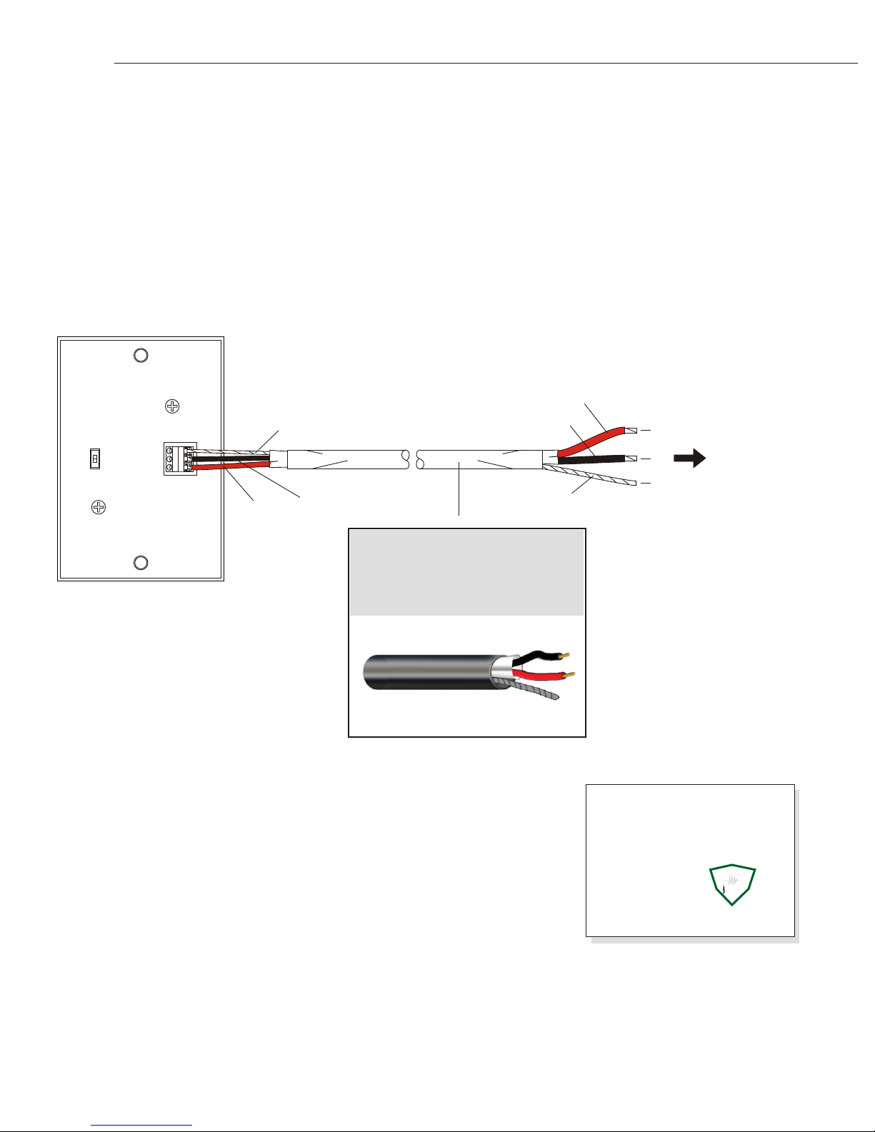
MICROPHONE CONNECTION:
RED wire (12 Vdc) goes to terminal A
BLACK wire (Audio Out) goes to terminal B
BARE wire (ground) goes to terminal C
PAGE 1 OF 2
INSTALLATION TIP: If area to be monitored for audio is noisy or has background disturbances, the
microphone should be positioned close to the subject 1½’ - 2½’, if possible.
LOUROE ELECTRONICS 6 9 5 5 VA L J E A N AVENUE, VAN NUYS, CA 91406 TEL (818) 994-6498 FAX (818)994-6458
CONNECTION TO LOUROE RECEIVING DEVICE
(Audio Base Station or Audio Interface Adapter:
All Louroe receiving devices (base stations, interface adapters) have a corresponding terminal block marked
A, B, C. Observing wire color code, connect other end of cable matching:
A to A
B to B
C to C
Also refer to installation instructions for the specific model base station or interface adapter. Maximum cable
run between microphone and receiving device is 1,000 ft. (305 m).
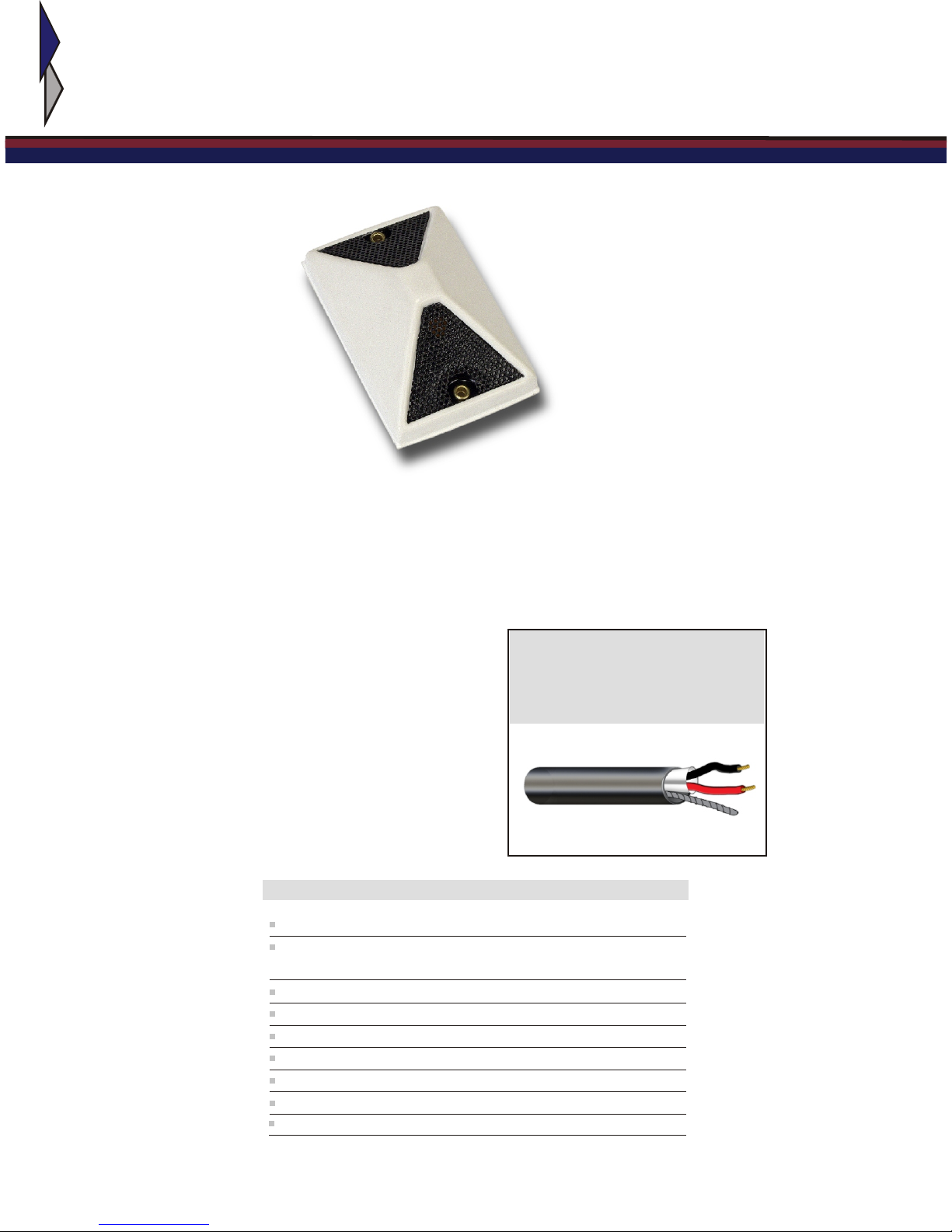
INSTALLATION AND OPERATING INSTRUCTIONS
The L-DT can be placed directly on a desktop or any flat surface. It has a weighted bottom with rubber
padding for positive grip. For best results, persons should be 2 - 3 ft. from the microphone.
MICROPHONE POSITIONING:
Model L-DT connects directly to any Louroe base station or audio interface adapter. A terminal block is
located on the back of Model L-DT Microphone housing, marked A, B, C.
A is 12 Vdc (power)
B is Audio Output
C is Ground
All Louroe base stations and audio interface adapters have a corresponding terminal block (A, B, C) for
each zone. Using recommended wiring, connect microphone to the receiving device as follows:
ELECTRICAL CONNECTION:
L-DT MIC 1/08