Lovibond SensoDirect 150 User manual

SensoDirect 150
MultiMeter Instrument - Instruction Manual
GB
pH/ORP DO
CD/TDS

22
Table of Contents
1. Specifications .................................................................................. 1
1.1 General Specifications .................................................................... 1
1.2 Electrical Specifications .................................................................. 2
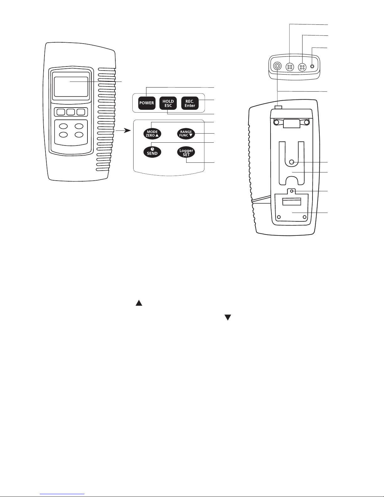
2. Front Panel Description.................................................................. 5
3. pH/mV Measuring and Calibration
Procedure ........................................................................................ 7
4. Conductivity/TDS Measuring and
Calibration Procedure .................................................................. 13
5. DO (Dissolved Oxygen) Measuring
and Calibration Procedure ........................................................... 18
6. Data Load, Data Record, Data Logger ........................................ 24
7. Advanced Adjustment Procedure................................................ 26
7.1 Check Memory Space ................................................................... 27
7.2 Clear Memory ............................................................................... 27
7.3 Date/Time Setting......................................................................... 27
7.4 Sample Time Setting..................................................................... 27
7.5 Auto Power Off Default Setting.................................................. 28
7.6 Temp. Unit Default Setting .......................................................... 28
7.7 pH Manual Temp. Value Setting.................................................. 28
7.8 CD Temp. Compensation Factor Setting...................................... 28
7.9 CD ( µS, mS ), TDS ( ppm ) Setting ............................................... 29
7.10 DO % Salt Compensation Value Setting ..................................... 29
7.11 DO Height (Altitude) Compensation Value Setting ................... 30
7.12 Escape from the Setting function................................................ 30
8. Data Output.................................................................................. 31
9. RS232 PC Serial Interface.............................................................. 33
10. Battery Replacement .................................................................... 35
11. System Reset ................................................................................. 35
11. Optional Accessories..................................................................... 36

1
1. Specifications
1.1 General Specifications
Circuit Custom microprocessor LSI
Display LCD size : 58 mm x 34 mm.
Measurement pH / Oxidation Reduction Potential (ORP)
Conductivity/Total Dissolved Solids (TDS)
Dissolved Oxygen (DO)
Temperature
Sampling Time of Data Log-
ger
1 second to 8 hours 59 minutes and
59 seconds
Data Hold Freeze the display reading.
Memory Recall Maximum and Minimum value
Power off •Auto shut off saves battery life; manual
shutoffpossiblebypressing“Power”button
for 2 seconds
•Default changeable: auto power off/
manual power off
•Withdefaultsetatautopoweroff,power
will off automatically after 10 minutes if no
buttonispressed.
Display lapse time Approx.1second.
Data Output RS 232 PC serial interface
Operating Temperature 0 to 50 °C (32 to 122°F) for the instrument
(notincludingprobes)
Operating Humidity Less than 80% rel. humidity
Power Supply •DC1.5Vwith4batteries(mignonsize;
TypeAA)
•DC9Vbyadapterinput
Power Current •Operation:approx.DC28mA
•Clock(poweroff):approx.DC1µA

2
Weight •instrument390g(batteriesincluded)
•withprotectivecovering620g
Dimension instrument:203x76x38mm•
with protective covering: approx.•
220 x 125 x 45 mm
1.2 Electrical Specifications (23± 5°C)
A. pH/mV
Measurement pH 0 to 14 pH
mV -1999mVto1999mV
Input Impedance 1012 ohm
Temperature Compensation
for pH measurement
Manual 0 to 100°C
(32 to 212°F)
Automatic(ATC) 0to65°C
(32 to 149 °F) with tem-
peratureprobe
pHCalibration 1to3pointcalibrationusing
pH7/pH4/pH10buffersolutions
Threepointcalibrationensuresbestlinearity
and accuracy
Measurement Range Resolution Accuracy
pH 0 to 14 pH 0.01 pH ± (0.02 pH + 2 digits)
mV -1999to1999mV 1mV ± (0.5 % pH + 2 digits)
*pHaccuracyisbasedoncalibratedmeteronly.

3
B. Conductivity
Conductivityprobe Carbon rod electrode for long
life
Function •Conduction(µS,mS)
•TotalDissolvedSolids(ppm)
•Temperature(°C,°F)
Temperature Compensation Automatic from 0 to 60°C
(32–140°F),
with temperature compensa-
tion factor variable between
0 to 5 % per °C
ProbeOperatingTemperature 0to60°C(32to140°F)
ProbeDimension Round, 22 mm diameter x
120 mm length
ProbeWeight approx.65g
Range Measurement Resolution Accuracy
200µS 0to200.0µS/cm 0.1µS/cm ± (2 % F.S.
+ 1 digit)
2 mS 0.2 to 2.000 mS / cm 0.001 mS / cm
20 mS 2 to 20.00 mS / cm 0.01 mS / cm
200 mS 20 to 200.0 mS / cm 0.1 mS / cm
F.S. = Full Scale

4
C. TDS (Total Dissolved Solids)
Range Measurement Resolution Accuracy
200 ppm 0 to 132 ppm 0.1 ppm ± (2 % F.S. +
1 digit)
2,000ppm 132to1,320ppm 1 ppm
20,000ppm 1,320to13,200ppm 10 ppm
200,000ppm 13,200to132,000ppm 100 ppm
F.S. = Full Scale
D. Temperature
Function Measurement Resolution Accuracy
°C 0°Cto60°C 0.1°C ± 0.8°C
°F 32°F to 140°F 0.1°F ± 1.5°F
E. Dissolved oxygen
OxygenProbe Polarographictypeoxygenprobe
ProbeCompensation
andAdjustment
Temperature 0to50°C,automatic,
(3 to 122 °F)
Salt 0 to 39 % Salt
Height 0 to 8900 meter
ProbeWeight approx. 195 g
ProbeSize Round,190mmlengthx28mmdiameter
Measurement Range Resolution Accuracy(23±5°C)
Dissolved Oxygen 0 to 20.0 mg/L 0.1 mg/L O2± 0.4 mg/L O2
OxygeninAir 0 to 100 % 0.1 % O2± 0.7 % O2

5
2. Front Panel Description (Fig. A)
A-1 Display
A-2 Power Button
A-3 REC Button (Enter Button)
A-4 HOLD Button (ESC Button)
A-5 Mode Button ( Up Button, Zero Button)
A-6 Function Button (Range Button, Down Button)
A-7 Send Button (Clock Button)
A-8 SET Button (Logger Button)
A-9 Stand
A-10 Battery Compartment Cover
A-11 Battery Cover Screw
A-12 Tripod Fix Nut
A-13 Temp. Socket (pH ATC Socket)
A-14 CD Socket
A-15 DO Socket
A-16 pH Socket (BNC Socket)
A-2
A-3
A-4
A-5
A-6
A-7
A-8
A-1
A-15
A-14
A-13
A-16
A-12
A-9
A-11
A-10

6
A-17 DC 9V Power Adapter Input Socket
A-18 RS-232 Output Terminal
A-19 System Reset Button
A-20 LCD Brightness Adjust
Attention:
Please do not put more than one electrode only into the water
sample when using an instrument that
works with various electrodes.
Only start the measurement for which the according electrode
is immersed in the sample.
A-17 A-18 A-19 A-20
DC IN
RS232
RESET

7
3. pH/mV Measuring and Calibration Procedure
Display layout
MeasurementValue
PH
Manual Temp.
25.0 °C
Temp. value Temp unit
pH
or
mV
Manual Temp. or
AutoTemp.
10.00
The meter default settings are as follows:
•The display unit is set to pH.
• The temperature unit is set to °C.
• Manual temperature setting (without ATC probe
connection)
• Auto power off.
• Data logger function sampling time: 2 seconds.

8
3.1 pH measurement (with manual temperature setting)
1)AttachthepHElectrodebyinstallingthe“ProbePlug“
(Fig.B-1)intothe“pHSocket/BNCSocket“(Page5,Fig.A-16).
2)Poweronthemeterbypressingthe“Power”buttononce.
3)Keeppressingthe“Mode”buttonuntilthedisplayofbottom
rightshows“pH“and“ManualTemp.“indicator.
4) Adjust the Manual Temp. value exactly to the same
temperature
as the solution. For procedure refer to chapter
7.7, page 28.
5)RemovecapandholdthepHElectrodebody(Fig.B-2)andcom-
pletelyimmersethe“SensingHead“(Fig.B-3)inthesolutionto
bemeasuredandgentlyswirltheprobe.
6)TheupperdisplaywillshowthepHvalue,thebottomleftdisplay
will show the Manual Temp. setting.
Fig. B
B-1
B-2
B-3
B-4

9
3.2 pH measurement (with ATC , automatic Temperature
Compensation)
1)Alltheproceduresarethesameasfor3.1“pHmeasurement
(manualtemperaturesetting)“,exceptforattachmentofa
temperatureprobebyinsertingtheplugofthetemperature
probeintothe“Temp.Socket“(Page5,Fig.A-13),andimmers-
ingthesensingheadofthetemperatureprobeintothemeasure-
ment solution.
2)TheupperdisplaywillshowthepHvalue,thebottomleft
displaywillshowtheTemp.valueofthemeasuredsolution,and
thebottomrightdisplaywillshow“AutoTemp.“asexamplebelow:
When not in use the “Electrode Sensing Head“ (Page 8, Fig.
B-3) should always be immersed in water by part-filling
the probe cap, (Page 8, Fig. B-4) and ensuring that the cap
is firmly lifted onto the probe. Failure to do so will reduce
probe life.
3.3 mV Measurement
TheinstrumenthasabuiltinmV(millivolt)measurementfunction,
whichenablesyoutomakeion-selective,ORP(oxidationreduction
potential),andotherprecisemVmeasurements.
1)AttachtheORPElectrodebyinstallingthe“ProbePlug“ofthe
ORPelectrodeintothe“pHSocket/BNCSocket“(Page5,Fig.A-16).
2)Poweronthemeterbypressingthe“Power”buttononce.
3)Keeppressingthe“Mode”buttonuntilthedisplayatbottom
rightshows“PH“and“ManualTemp.“indicator.
PH
Auto Temp.
25.0 °C
7.01

10
Press the “Function” button once so that the bottom right
display shows “mV“ .
4)TheupperdisplaywillshowthemVvalue.
3.4 pH calibration
Calibration - Introduction
An“ideal”pHElectrodegenerates0mVatpH7.00(177.4mVat
pH4).Themeterhasbeencalibratedwithsignalswhichsimulate
the“ideal”pHElectrode(basedon25°Cambientenvironment).
HowevernoteverypHElectrodeisasaccurateasthe“ideal”one,
socalibrationproceduresarenecessarybeforersttimemeasure-
ment.Inadditiontocalibrationbeforersttimemeasurement,us-
ersarealsorecommendedtocarryoutregularcalibrationtoensure
high accuracy measurements.
Required Equipment for Calibration
1)pHElectrode.
2)pHbuffersolutions.
Calibration Procedure
1)AttachthepHElectrodebyinstallingthe“ProbePlug“(Page8,
Fig.B-1)intothe“pHSocket/BNCSocket“(Page5,Fig.A-16).
2)Poweronthemeter,setthemodetopHmeasurement,andthe
bottomrightdisplaywillshow“PH“.
3)Adjustthe“TemperatureCompensationValue“tomakeitthe
sametemperatureasthepHbuffersolution.
• Manual temperature compensation value adjustment
procedure, refer to 7-7, page 28.
• Automatic temperature compensation, refer to 3.2,
Page 9.
4)Holdthe“pHElectrodebody“(Page8,Fig.B-2)andcompletely
immersethe“SensingHead“(Page8,Fig.B-3)inthebuffersolu-
tionandgentlyswirltheprobe.ThedisplaywillshowthepHvalue.

11
5)Pressthe“REC”buttonand“HOLD”buttonatthesametime.
Thedisplaywillshowthefollowingscreenasanexample.Now
release.
6)• IfthebuffersolutionispH7.0(±1pH),theupperdisplaywill
show 7.00 automatically.
• IfthebuffersolutionispH4.0(±1pH),theupperdisplaywill
show 4.00 automatically.
• IfthebuffersolutionispH10.0(±1pH),theupperdisplay
will show 10.00 automatically.
• IfthebuffersolutionvalueisbeyondpH7.00,pH4.00,
pH10.00(forexample7.01,4.02,10.03)thenuse
“
”button,“ ”buttontoadjustthedisplayvaluetoexactly
matchthepHbuffersolutionvalue.
7)Pressthe“Enter”buttontwicetosavethecalibrationdataand
nishthecalibrationprocedure.
8)Thedescribedprocedurecanbeperformedforthefollowing
calibrationpoints:
pH7 calibration
pH4 calibration
pH10 calibration
•CalibrationshouldalwaysstartwithpH7,followedbypH4and/
orpH10calibration.
•Rinsetheelectrodewithdistilledwaterbeforeeachcalibration
point.
PH CAL.
^, v Enter : Y
23.5 °C
7.00

12
•Repeattheabovecalibrationproceduresatleasttwicetoensure
accuracy.
3.5 ORP calibration
1)AttachtheORPelectrode(optional,ORP-14)byconnectingthe
ORP electrode to the meter.
2)Poweronthemeter,andsetthemodeandfunctionto“mV“
(refertochapter3.3,Page9).
3) Immerse the sensing head of the ORP electrode in the ORP
standardbuffersolution.TheupperdisplaywillshowtheORP
valueinmV.
4)Pressthe“REC”buttonand“HOLD”buttonatthesametime.
Thedisplaywillshowthefollowingscreenasanexample.Now
release.
5)Use“ ”button,“ ”buttontoadjusttheupperdisplayvalueto
exactlymatchtheORPbuffersolutionvalue.Pressthe“Enter”
buttontwicetosavethecalibrationdataandnishthecalibra-
tion procedure.
• ORP calibration is only possible if the ORP buffer solution
value is > 100 mV.
• ORP calibration at less than 100 mV is not permitted.
mV
Adjust
201
235
Aiv

13
4. Conductivity/TDS Measuring and Calibration Procedure
Display layout MeasurementValue
200.0 µS
Auto Range
24.2 °C
Temp. value Temp unit AutoorManual
range
19.00
The meter default settings are as follows:
•Thedisplayunitissettoconductivity(µS,mS).
•Thetemperatureunitissetto°C.
•Temp.compensationfactorissetto2.0%per°C.
•Autorange.
•Autopoweroff.
•Dataloggerfunctionsamplingtime:
2 seconds.
Range
scale

14
4.1 µS, mS measurement
1)AttachtheConductivityProbebyinstallingthe“ProbePlug“
(Fig.C-1)intothe“CDSocket“(Page5,Fig.A-14).
2)Poweronthemeterbypressing“Power”buttononce.
3)Keeppressingthe“Mode”buttonuntilthebottomrightdisplay
showsavalue(e.g.“200mS“)and“AutoRange“.
4)Removeprobecapandholdtheprobebody(Fig.C-2)andcom-
pletelyimmersethe“SensingHead“(Fig.C-3)inthesolutionto
bemeasured.Swirltheprobetoletanyairbubbleescapefrom
the sensing head.
5)Thedisplaywillshowtheconductivityvaluesineither“mS/cm”
or“µS/cm”.Atthesametimethebottomleftdisplaywillshow
the Temp. value of the measured solution.
Fig. C
C-1
C-2
C-3

15
Manual range operation
The meter default is set to auto range mode. Under auto range
measurement,thebottomrightdisplaywillshowthe“Auto
Range“indicator.Ifmanualrangemodeisrequired,theprocedures
are as follows:
1)Pressthe“Range”buttoncontinuouslyforatleasttwoseconds
untilthebottomrightdisplayshowsthe“ManualRange“indica-
tor.Releasethe“Range”button.Nowthemeterissetformanual
range operation.
2)Pressthe“Range”buttononcetochangetherange.Therange
(200µS,2mS,20mS,200mS)willshowunderthemeasure-
ment value.
3)• Ifthedisplayshows“ ---- “,itindicatesanoverrange.
Selectthenext,higherrange.
• Ifthedisplayshows“ ----“,itindicatesanunderrange.
Selectthenext,lowerrange.
4)TochangeManualRangebacktoAutoRange,pressthe
“Range”buttoncontinuouslyforatleasttwosecondsuntilthe
bottomrightdisplayshowsthe“AutoRange“Indicator.Release
the“Range”button.NowthemeterissetforAutorangemode
again.
Change the Temp. unit to °F
TochangetheTemp.unitfrom°Cto°F,pleaserefertopage28,
chapter7.6(Temp.UnitDefaultSetting)
Change the Temp. Coefficient Factor
The default Temp. compensation factor value of the measurement
solutionissetto2.0%per°C.Tochangeit,pleaserefertopage
28,chapter7.8(Temp.CompensationFactorSetting).

16
4.2 TDS (ppm) measurement
Measuringproceduresarethesameasabove4.1 Conductivity (µS,
mS) measurement,exceptforchangingthedisplayunitfromµS,
mStoppm.Fordetailedprocedurespleaserefertopage29,chap-
ter7.9CD(µS,mS),TDS(ppm)Setting.
4.3 Calibration
1)Obtainathestandardconductivitysolution:
For example :
• 2mSrangecalibrationsolution:
1.413 mS Conductivity Standard Solution
• 200µSrangecalibrationsolution:
80 µS Conductivity Standard Solution
• 20mSrangecalibrationsolution:
12.88 mS Conductivity Standard Solution
or other Conductivity Standard Solution
2)Installthe“ProbePlug“(Page14Fig.C-1)intothe“CDSocket“
(Page5,Fig.A-14).
3)Poweronthemeter,andsetthemodetoconductivity
measurement(µS,mS).
4)Holdtheprobebody(Page14,Fig.C-2)andcompletelyimmerse
“SensingHead“(Page14,Fig.C-3)inthestandardsolution.
Swirltheprobetoletanyairbubbleescapefromthesensing
head. The display will show the conductivity mS ( mS ) values.
5)Pressthe“REC”buttonand“HOLD”buttonatthesametime.
Thedisplaywillshowthefollowingscreen,asanexample.Now
release.

17
6)Use“ ”button(Page5,Fig.A-5),“ ”buttontoadjustthe
upper display value to match the standard conductivity value.
7)Pressthe“Enter”buttontwicetosavethecalibration
data,andnishthecalibrationprocedure.
• If only one calibration point is needed, just set the 2 mS
range (1.413 mS Cal.).
• A multi-point calibration procedure should always start
with 2 mS range (1.413 mS Cal.), then proceed to other
ranges (20 µS range, 20 mS range or 200 mS range) if
necessary.
CD CAL.
^, v ENTER: Y
23.5 °C
1.413

18
Display layout MeasurementValue
% O2
24.2 °C
Temp. value Temp unit Temp. unit
% O2or mg/L
20.9
5. DO (Dissolved Oxygen) Measuring and Calibration
Procedure
ATTENTION: Make sure the Oxygen probe is filled with Elec-
trolyte!
To fill the Probe‘s Electrolyte, refer to chapter 5.3 “Probe
maintenance“, page 22.
The meter default settings are as follows:
•Thedisplayunitissetto%O2.
•Thetemperatureunitissetto°C.
•Autopoweroff.
•Dataloggersamplingtime:2seconds.
Table of contents