manuals.online logo
Brands
  1. Home
  2. •
  3. Brands
  4. •
  5. Lowrance
  6. •
  7. Compass
  8. •
  9. Lowrance SIMRAD B and G Precision 9 User manual

Lowrance SIMRAD B and G Precision 9 User manual

Scan to save a copy
Precision™ 9 Installation Guide
The Precision™ 9 compass outputs magnetic heading for sail and powerboats. It connects to the vessel’s NMEA 2000®
network, allowing you to set up and control it from display units on the network. The compass outputs magnetic heading
data suitable for autopilot steering as well as rate of turn, pitch, roll and heave.
¼Note: Pitch and roll are called trim and heel for B&G®products.
Installation
The Precision™ 9 compass can be mounted on a at, horizontal or vertical surface, athwart ship or along ship. Select a
location that provides a solid mounting place free from vibration (as much as possible), and as close as possible to the vessel’s
center of pitch and roll, i.e. close to the water line.
It should be as far away as possible from:
• disturbing magnetic interferences, for example, engines (minimum of 2 m)
• ignition cables
• large metal objects, particularly the autopilot drive unit.
On steel hull vessels, the compass can be mounted 0.75 - 1 m (2.5 - 3.3 ft) above the wheel house on a non-magnetic stand, if
no other options are available.
¼Warning: Never mount the compass upside down. Level the compass as close to horizontal as possible.
To mount the compass directly to a at, horizontal surface:
1. Use the supplied direct mount template to mark 2 screw holes and a hole for the network cable.
¼Note: Position the compass so it is parallel to the vessel’s center line.
2. Drill holes at the marks and position the compass so the holes line up.
3. Use 2 pan head or roundhead machine screws to secure the compass to the surface.
¼Note: You must supply your own screws for direct mounting. Screw recommendations: Ø 10G - 4.8 mm - 3/16". Max 7.5 mm
(0.29”). Length is determined by the surface thickness. Screws must be non magnetic.
To mount the compass to a at, vertical surface, such as a bulkhead:
1. Use the supplied bracket template to mark 2 holes to a vertical surface, then drill holes at the marks.
2. Use the supplied self-tapping screws to attach the supplied bracket to the wall.
3. Position the compass on the bracket so the mounting holes line up.
4. Insert the supplied machine screws and tighten them loosely (only half way).
5. Manually swivel the compass so it’s orientation is parallel to the vessel’s center line.
6. Fully tighten the mounting screws to secure the compass.
Wiring
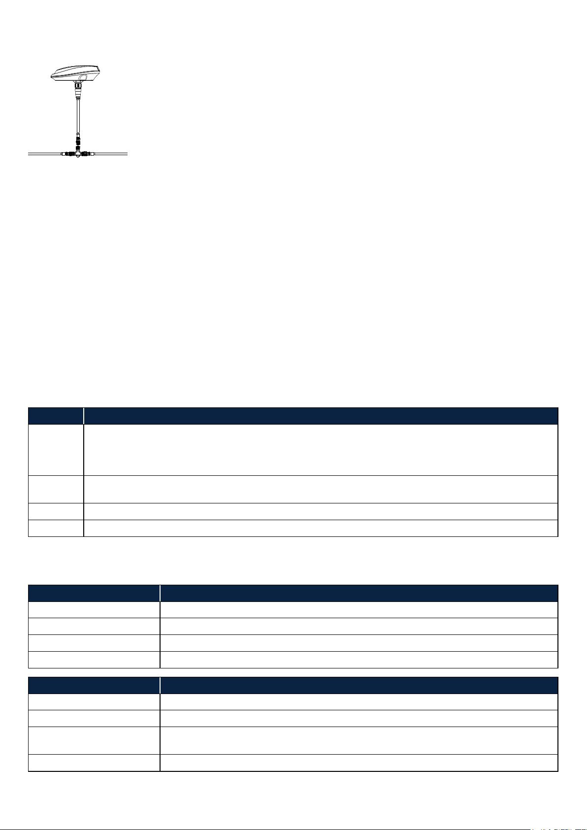
Connect the Precision™ 9 compass to your NMEA 2000®network using the supplied tee connector.
Calibration
After installing and wiring your compass, you should calibrate it to compensate for the deviation (local magnetic eld) on
board the vessel, and adapt the sensors to the earth’s magnetic eld strength.
Your Precision™ 9 compass supports two calibration modes:
• Auto calibration
• Manual calibration
Auto calibration
There are 4 different auto calibration modes. In all modes, data is continuously collected and new calibration parameters
calculated - the difference is in how and when new parameters are used.
The default mode is Auto, and for most users it’s not necessary to change this. However, if you wish to make sure the
compass doesn’t change its calibration, you can set it to Locked once you're satised with the performance.
To change the mode, go to your compatible display unit and nd your Precision™ 9 compass in the devices list, usually under
Settings > Network (or Boat network) > Device list (or Devices) > Precision-9. Open the compass conguration screen and
select a different mode from the Compass auto calibration drop-down.
¼Note: If the Compass auto calibration option isn't available on your display unit, go directly to the Manual calibration
section of this installation guide.
Mode Behavior
Auto The compass accumulates calibration parameters from normal use on the water. If the compass detects
the new calibration parameters are more accurate than the stored values, the new calibration parameters
are phased in over a period of time. Note: New calibration parameters are phased in only if the existing
parameters are invalid.
Locked In this mode, the compass won’t change the parameters in use by itself. If new parameters are deemed better
than the current ones, the following warning dipslays, "Parameters in use are not valid”.
On New calibration parameters are phased in whenever they are deemed better than the existing ones.
Off In this mode, no auto calibration parameters are used, and the compass uses manual calibration.
Statuses and warnings
Calibration status and warning information also displays on the compass conguration screen.
Status Description
Is not calibrated The needed magnetic raw data is not yet collected.
Is calibrating New calibration parameters have been found, and are being phased in.
Is calibrated Calibration parameters have been found and are being used.
- - - Auto calibration mode is set to Off.
Warning Description
First calibration in progress Data for rst calibration is being collected.
No warning Performance of current parameters is deemed good.
Parameters in use are not
valid
Current parameters are not valid. If this is seen when the mode is Locked, the mode should
at least temporarily be set to On or Auto, to switch parameters.
- - - Auto calibration mode is set to Off.
Manual calibration
To manually calibrate your Precision™ 9 compass, go to your compatible display unit and nd it in the devices list, usually
under Settings > Network (or Boat network) > Device list (or Devices) > Precision-9. Select Calibrate or Recalibrate
compass (depending on your display unit) and follow the on-screen instructions.
¼Note: If your display unit supports auto calibration, the auto calibration mode must rst be set to Off.
Important points:
• Manually calibrate your compass in calm sea conditions with minimal wind and current.
• Ensure there's enough open water around the vessel to maneuver a turn of about 390 degrees.
• Maintain a turn rate of about 2-3 degrees per second until you see a notication that the calibration is complete.
¼Note: If an autopilot is congured, a setup guide automatically takes you through compass calibration, without having to
go through the Settings menu.
¼Note: For optimal performance, you should recalibrate the compass if the vessel has traveled far from where it was
previously calibrated. Recalibration may be required because the strength of the earth’s magnetic eld varies in different
geographic locations.
Data
To see the data your compass is generating, select Data or Show details (depending on your display unit) under Settings >
Network (or Boat network) > Device list (or Devices) > Precision-9.
Offsets
After calibrating your compass, you should apply offsets for the heading, pitch and roll outputs to compensate for any
mounting alignment errors.
To apply pitch and roll offsets:
1. Ensure the vessel is stationary at the dock, loaded in normal trim.
2. Open the compass data screen by selecting Data or Show details (depending on your display unit) and take note of the
pitch and roll output values.
3. Open the compass conguration screen and adjust the pitch and roll offsets.
4. Return to the data screen to conrm the pitch and roll output values are 0.
The heading offset compensates for any difference between the vessel’s center line (A) and the
compass lubber line (B).
To apply the heading offset:
1. Open the compass data screen by selecting Data or Show details (depending on your display
unit) and take note of the heading output value.
2. If necessary, change the heading reference on your display unit (Settings > Units (or
Preferences) > Heading) so it's the same as the compass heading (°Mor °T).
3. Use a chart or chartplotter to nd the bearing from the vessel position to a visible object.
4. Steer the vessel so its center line aligns with the bearing line pointing towards the object.
5. Open the compass conguration screen and adjust the heading offset so the bearing value and the compass heading
output are the same.
¼Note: The compass heading and bearing values may be damped. Allow time for the heading and bearing values to settle
before applying offset.
Dimensions
133 mm (5.23”)
119 mm (4.69”)
126 mm (4.96”)
72 mm (2.83”)
36 mm
(1.42”)
90 mm (3.54”)
119 mm (4.69”)
36 mm
(1.42”)
90 mm (3.54”)
126 mm (4.96”)
B
A
x
*988-10984-003*
Technical specications
Module weight 165 g (5.8 oz)
Bracket weight 130 g (4.6 oz)
Supply and interface 8-16 V via NMEA 2000®
Power consumption 0.4 W
Calibration Automatic or manual
Repeatability ± 1.0° (or better)
Roll/pitch range ± 45°
Heading accuracy ± 2° after calibration
NMEA 2000®
Load equivalence no. (LEN) 1
Ports (input/output) 1
Output Messages: PGN 127250, 127251, 127257, 127252
Data: Magnetic heading (20 Hz), rate of turn (20 Hz), pitch/roll (10 Hz),
heave (10 Hz)
Status and warning information
Dynamic performance
- with random excitation of ± 10° at max 1 Hz Heading error <2°
- with heading step input of 90° at a rate of 10°/s Heading error 10 sec. after turn <2°
Environmental protection IPX7
Compass safe distance 0.5 m (1.7 ft)
Temperature range
Operation temperature -25 to +65°C (-13 to +149°F)
Storage temperature -30 to +70°C (-22 to +158°F)
Cable supplied 4.5 m (15 ft) incl. connector
Mounting Horizontal or vertical surface
Material Plastic
Compliance statements
Declarations
The relevant declarations of conformity are available at: www.simrad-yachting.com, www.lowrance.com and www.bandg.com.
United Kingdom
The Precision™ 9 compass complies with UKCA under Electromagnetic Compatibility Regulations 2016.
Europe
The Precision™ 9 compass complies with CE under Electromagnetic Compatibility Directive 2014/30/EU.
United States of America
Note: The user is cautioned that any changes or modications not expressly approved by the party responsible for compliance could void the user's authority to operate the
equipment.
Australia and New Zealand
The Precision™ 9 compass complies with the requirements of Level 2 devices of the Radiocommunications (Electromagnetic Compatibility) Standard 2017.
Note: This product includes code from the Eigen project licensed under the MPL v2.0 license, available from http://eigen.tuxfamily.org/.
Copyright
Copyright © 2022 Navico Holding AS.
Trademarks
®Reg. U.S. Pat. & Tm. Off, and ™ common law marks. Visit www.navico.com/intellectual-property to review the global trademark rights and accreditations for Navico Holding AS
and other entities.
Translated documentation
Translated versions of this installation guide are available at: www.simrad-yachting.com, www.lowrance.com and www.bandg.com.
Warranty
The warranty card is supplied as a separate document. In case of any queries, refer to the brand website of your unit or system.

Popular Compass manuals by other brands

Jula 651-001 Installation and operating instructions

Jula

Jula 651-001 Installation and operating instructions

Bresser National Geographic 90-79000 operating instructions

Bresser

Bresser National Geographic 90-79000 operating instructions

Brunton 85R Directions for use

Brunton

Brunton 85R Directions for use

B&G Network Network System user manual

B&G Network

B&G Network Network System user manual

Tokimec TG-6000 Service manual

Tokimec

Tokimec TG-6000 Service manual

Suunto SK-7 user guide

Suunto

Suunto SK-7 user guide

Riviera ARTICA 2 3/4 user manual

Riviera

Riviera ARTICA 2 3/4 user manual

Silva Carabiner 28 Product introduction

Silva

Silva Carabiner 28 Product introduction

Riviera BW2 instructions

Riviera

Riviera BW2 instructions

Riviera Polare BP1 user manual

Riviera

Riviera Polare BP1 user manual

IST GP-4000 manual

IST

IST GP-4000 manual

Astra A5022 user manual

Astra

Astra A5022 user manual

TFA HiTRAX TREK operating instructions

TFA

TFA HiTRAX TREK operating instructions

patura 150901 user manual

patura

patura 150901 user manual

Raymarine ST60+ SPEED INSTRUMENT Owner's handbook

Raymarine

Raymarine ST60+ SPEED INSTRUMENT Owner's handbook

Silva EXPEDITION SERIES Product information

Silva

Silva EXPEDITION SERIES Product information

manuals.online logo
manuals.online logoBrands
  • About & Mission
  • Contact us
  • Privacy Policy
  • Terms and Conditions

Copyright 2025 Manuals.Online. All Rights Reserved.