LRAD 500X
Table of Contents
Table of Contents............................................................................................................................ 2
List of Figures .................................................................................................................................. 2
List Tables........................................................................................................................................ 3
1.0 Important Safety Information.................................................................................................. 4
Power Cord Termination................................................................................................................. 5
System Description ......................................................................................................................... 5
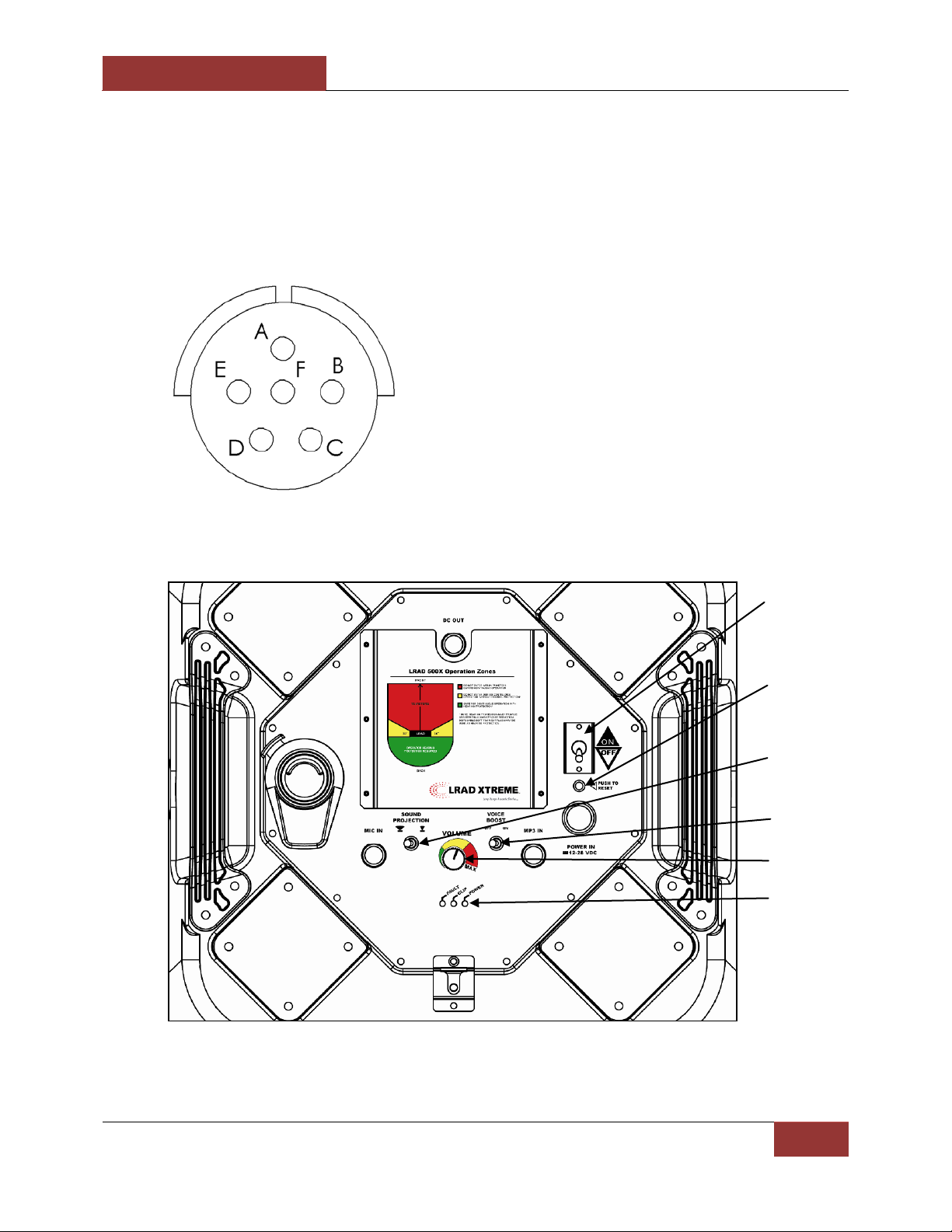
Operator Controls and Connections............................................................................................... 7
Rear Panel Connections .............................................................................................................. 7
Auxiliary DC Output .................................................................................................................... 7
DC Power Input ........................................................................................................................... 8
MP3 Player Input ........................................................................................................................ 8
Microphone Input ....................................................................................................................... 9
Rear Panel Controls and Indicators............................................................................................. 9
Main Power Switch ................................................................................................................... 10
Resettable Breaker.................................................................................................................... 10
Sound Projection Switch ........................................................................................................... 10
Volume Control......................................................................................................................... 10
Voice Boost Switch.................................................................................................................... 11
LED Status Indicators ................................................................................................................ 11
System Setup................................................................................................................................. 11
Operation – Hailing and Warning ................................................................................................. 15
Care and Maintenance.................................................................................................................. 16
Troubleshooting and Repairs........................................................................................................ 17
Schematic Diagram ....................................................................................................................... 19
Spare Parts/Support...................................................................................................................... 20
Specifications ................................................................................................................................ 21
15.0 Technical Support ................................................................................................................ 22
List of Figures
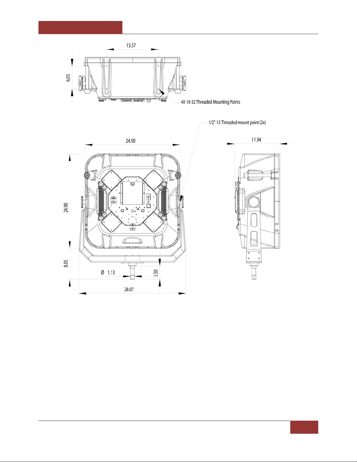
Figure 1: LRAD-500X outside dimensions and mounting points. Operator Controls and
Connections .................................................................................................................................... 6
Operator Controls and Connections............................................................................................... 7
Figure 2: LRAD-500X mounting point details................................................................................ 12
Figure 3: MP3 Player Controls ...................................................................................................... 14
Figure 4: Do not attempt to listen to the output side of the unit. ............................................... 16