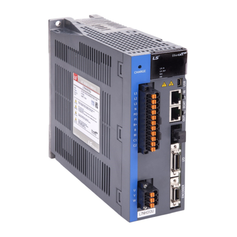
LS ELECTRIC L7NH Series User manual

Read all safety precautions before using this product.
After reading this manual, store it in a readily accessible
location for future reference.
Safety Precautions
The Best Choice for the Most Benefit!
At LS Mecapion, we are committed to providing premium benefits to all of our
customers.
AC Servo User Manual
L7NH Series
400
AC SERVO DRIVE
Xmotion
L7NH Series Us
er Manual
LS
ELECTRIC always tries its best to bring the greatest benefit to its customers.


Introduction
i
Introduction
Hello. Thank you for choosing LS ELECTRIC L7NH Series.
This user manual describes how to use this product safely and efficiently.
Failure to comply with the guidelines outlined in this manual may cause personal injury or damage to
the product. Be sure to read this manual carefully before using this product and follow all guidelines
contained therein.
The contents of this manual are subject to change without notice.
The reproduction of part or all of the contents of this manual in any form, by any means or for
any purpose is strictly prohibited without the explicit written consent of LS ELECTRIC.
LS ELECTRIC retains all patents, trademarks, copyrights and other intellectual property rights to
the material in this manual. The information contained in this manual is only intended for use
with LS ELECTRIC products.
Safety precautions are categorized as either Warnings or Cautions, depending on the severity
of the precaution.
Precautions Definition
Danger Failure to comply with these guidelines may cause serious injury or death.
Caution Failure to comply with these guidelines may cause personal injury or property
damage.
Precautions listed as Cautions may also result in serious injury.
Electric Safety Precautions
Danger
Before wiring or inspection tasks, turn off the power. Wait 15 minutes until the charge
lamp goes off, and then check the voltage.
Ground both the servo drive and the servo motor.
Only specially trained technicians may perform wiring on this product.
Install both the servo drive and servo motor before performing any wiring.
Do not operate the device with wet hands.
Do not open the servo drive cover during operation.
Do not operate the device with the servo drive cover removed.
Even if the power is off, do not remove the servo drive cover.
Fire Safety Precautions
Caution
Install the servo drive, the servo motor, and the regenerative resistor on non-
combustible materials.
Disconnect the input power if the servo drive malfunctions.

Introduction
ii
Installation Precautions
Store and operate this product under the following environmental conditions.
Environment Conditions
Servo drive Servo motor
Operating
temp. 0 ~ 50 ℃0 ~ 40 ℃
Storage temp. -20 ~ 65 ℃-10 ~ 60 ℃
Operating
humidity Below 90% RH (no condensation) 20~80% RH(no condensation)
Storage
humidity
Altitude 1000 m or lower
Spacing
When installing 1 unit:
More than 40 mm at the top and
bottom of the control panel
More than 10 mm on the left and right
sides of the control panel
When installing 2 or more units:
More than 100 mm at the top of the
control panel
More than 40 mm at the bottom of the
control panel
More than 30 mm on the left and right
sides of the control panel
More than 2 mm between units
Refer to Section 2.2.1, "Wiring the
Control Panel."
Other
Ensure the installation location is free from dust, iron, corrosive gas,
and combustible gas.
Ensure the installation location is free from vibrations or the potential
for hard impacts.
Caution
Install the product with the correct orientation.
Do not drop the product or expose it to hard impact.
Install this product in a location that is free from water, corrosive gas, combustible
gas, or flammable materials.
Install this product in a location capable of supporting the weight of this product.
Do not stand on the product or place heavy objects on top of it.
Always maintain the specified spacing when installing the servo drive.
Ensure that there are no conductive or flammable debris inside the servo drive or the
servo motor.
Firmly attach the servo motor to the machine.
Install the servo motor with a correctly oriented decelerator.
Do not touch the rotating unit of the servo motor during operation.
Do not apply excessive force when connecting the couplings to the servo motor shaft.
Do not place loads on the servo motor shaft that exceed the specified amount.

Introduction
iii
Wiring Precautions
Caution
Always use an AC 380-480 V power input for the servo drive.
Always connect the servo drive to a ground terminal.
Do not connect commercial power directly to the servo motor.
Do not connect commercial power directly to the U, V, W output terminals of the servo
drive.
Connect the U, V, W output terminals of the servo drive directly to the U, V, W input
terminals of the servo motor, but do not install magnetic contactors between the wires.
Always use pressurized terminals with insulation tubes when connecting the servo
drive power terminal.
When wiring, be sure to separate the U, V, and W cables for the servo motor power
and encoder cable.
Always use the robot cable if the motor moves.
Before you perform power line wiring, turn off the input power of the servo drive, and
then wait until the charge lamp goes off completely.
Startup Precautions
Caution
Check the input voltage (AC 380-480 V) and power unit wiring before supplying power
to the device.
The servo must be in the OFF mode when you turn on the power.
Before you turn on the power, check the motor's ID and the encoder pulse for L7NHB
□□□.
Set the motor ID[0x2000], encoder type[0x2001] and the encoder pulse [0x2002] for
L7NHB□□□ first after you turn on the power.
After you complete the above settings, set the drive mode for the servo drive that is
connected to the upper level controller in [0x6060].
Refer to Chapter 1.4 "System Configuration" to perform I/O wiring for the servo drive
according to each drive mode.
You can check the ON/OFF state for each input terminal of I/O at [0x60FD].
Handling and Operating Precautions
Caution
Check and adjust each parameter before operation.
Do not touch the rotating unit of the motor during operation.
Do not touch the heat sink during operation.
Be sure to attach or remove the I/O and ENCODER connectors when the power is off.
Extreme change of parameters may cause system instability.

Introduction
iv
Usage Precautions
Caution
Install an emergency cut-off switch which immediately stops operation in an
emergency.
Reset the alarm when the servo is off. Be warned that the system restarts
immediately if the alarm is reset while the servo is on.
Use a noise filter or DC reactor to minimize electromagnetic interference. This
prevents nearby electrical devices from malfunctioning due to interference.
Only use approved servo drive and servo motor combinations.
The electric brake on the servo motor stops operation. Do not use it for ordinary
braking.
The electric brake may malfunction if the brake degrades or if the mechanical
structure is improper (for example, if the ball screw and servo motor are combined via
the timing belt). Install an emergency stop device to ensure mechanical safety.
Malfunction Precautions
Caution
Install a servo motor with an electric brake or separate the brake system for use
during emergencies or device malfunctions.
If an alarm occurs, solve the underlying cause of the problem. After solving the
problem and ensuring safe operation, deactivate the alarm and resume operation.
Do not approach the machine until the problem is solved.
Repair/Inspection Precautions
Caution
Before performing servicing tasks, turn off the power. Wait 15 minutes until the charge
lamp goes off, and then check the voltage. Enough voltage may remain in the
condenser after the power is off to cause an electric shock.
Only authorized personnel may repair and inspect the device or replace its parts.
Do not modify this device in any way.
General Precautions
Caution
This user manual is subject to change due to product modification or changes in
standards. If such changes occur, we issue a new user manual with a new product
number.
Product Application
Caution
This product is not designed or manufactured for machines or systems intended to
sustain human life.
This product is manufactured under strict quality control conditions. Nevertheless,
install safety devices if installing the device in a facility where product malfunctions
may result in a major accident or a significant loss.

Introduction
v
EEPROM Lifespan
Caution
The EEPROM is rewritable up to 4 million times for the purpose of recording
parameter settings and other information. The servo drive may malfunction if the total
number of the following tasks exceeds 4 million, depending on the lifespan of the
EEPROM.
EEPROM recording as a result of parameter changes
EEPROM recording as a result of an alarm

Table of Contents
vi
Table of Contents
1. Product Configuration.......................................................................................1-1
1.1 Product Verification .......................................................................................................1-1
1.2 Product Specifications...................................................................................................1-2
1.3 Part Names ...................................................................................................................1-4
1.3.1 Servo Drive Parts ...........................................................................................1-4
1.3.2 Servo Motor Parts ..........................................................................................1-9
1.4 System Configuration Example ...................................................................................1-10
2. Wiring and Connection......................................................................................2-1
2.1 Installation of Servo Motor.............................................................................................2-1
2.1.1 Operating Environment...................................................................................2-1
2.1.2 Preventing Impact ..........................................................................................2-1
2.1.3 Motor Connection...........................................................................................2-1
2.1.4 The Load Device Connection ......................................................................... 2-2
2.1.5 Cable Installation............................................................................................2-2
2.2 Installation of Servo Drive..............................................................................................2-3
2.2.1 Installation and Usage Environment...............................................................2-3
2.3 Internal Block Diagram of Drive.....................................................................................2-4
2.3.1 L7NH Drive Block Diagram (L7NHB010U~ L7NHB035U) ..............................2-4
2.3.2 L7NH Drive Block Diagram (L7NHB050U~ L7NHB075U) ..............................2-5
2.3.3 L7NH Drive Block Diagram (L7NHB150U) .....................................................2-6
2.4 Power Supply Wiring.....................................................................................................2-7
2.4.1 Power Supply Wiring Diagram........................................................................ 2-8
2.4.2 Power Circuit Electrical Components ............................................................2-11
2.4.3 Regenerative Resistor Options.....................................................................2-17
2.5 Wiring for Input/Output Signals....................................................................................2-18
2.5.1 Names and Functions of Digital Input/Output Signals...................................2-18
2.5.2 Names and Functions of Analog Input/Output Signals..................................2-20
2.5.3 Examples of Connecting Input/Output Signals .............................................2-21
2.5.4 Examples of Connecting Input/Output Signals .............................................2-23
2.6 Wiring of Encoder Signal (ENCODER)........................................................................2-24
2.6.1 Quadrature Encoder Signaling Unit Wiring...................................................2-24
2.6.2 Serial Encoder Signaling Unit Wiring............................................................ 2-25
2.6.3 Multi-Turn Encoder Signaling Unit Wiring.....................................................2-27
2.6.4 Tamagawa Encoder Signaling Unit Wiring.................................................... 2-28
2.6.5 EnDat 2.2 Encoder Signaling Unit Wiring..................................................... 2-29
2.7 Wiring for Safety Function Signals (STO)....................................................................2-30
2.7.1 Names and Functions of Safety Function Signals ........................................2-30
2.7.2 Example of Connecting Safety Function Signals..........................................2-31
2.7.3 Bypass Wiring of Safety Function Signal......................................................2-32
2.8 Wiring for EtherCAT Communication Signals .............................................................. 2-33
2.8.1 Names and Functions of EtherCAT Communication Signals........................2-33
2.8.2 Example of Drive Connection.......................................................................2-34
3. EtherCAT Communication.................................................................................3-1
3.1 Structure of CANopen over EtherCAT ...........................................................................3-1

Table of Contents
vii
3.1.1 EtherCAT State Machine ................................................................................3-2
3.2 Status LED ....................................................................................................................3-3
3.3 Data Type......................................................................................................................3-5
3.4 PDO assignment ...........................................................................................................3-5
3.5 Synchronization Using the DC (Distributed Clock).........................................................3-8
3.6 Emergency Messages...................................................................................................3-9
4. CiA402 Drive Profile...........................................................................................4-1
4.1 State machine................................................................................................................4-1
4.2 Operation Modes...........................................................................................................4-3
4.3 Position Control Modes .................................................................................................4-5
4.3.1 Cyclic Synchronous Position Mode ................................................................4-5
4.3.2 Profile Position Mode......................................................................................4-8
4.4 Velocity Control Mode..................................................................................................4-13
4.4.1 Cyclic Synchronous Velocity Mode...............................................................4-13
4.4.2 Profile Velocity Mode....................................................................................4-16
4.5 Torque Control Modes.................................................................................................4-19
4.5.1 Cyclic Synchronous Torque Mode ................................................................4-19
4.5.2 Profile Torque Mode .....................................................................................4-21
4.6 Homing........................................................................................................................4-23
4.6.1 Homing Method............................................................................................4-24
4.7 Touch Probe Function..................................................................................................4-38
5. Drive Application Functions..............................................................................5-1
5.1 Drive Front Panel ..........................................................................................................5-1
5.1.1 7-Segment for indicating servo status.............................................................5-1
5.2 Input/Output Signals Setting..........................................................................................5-4
5.2.1 Assignment of Digital Input Signals ................................................................5-4
5.2.2 Assignment of Digital Output Signals..............................................................5-6
5.2.3 Use of User I/O...............................................................................................5-8
5.3 Electric Gear Setup .....................................................................................................5-15
5.3.1 Electric Gear.................................................................................................5-15
5.3.2 Example of Electric Gear Setup....................................................................5-16
5.4 Settings Related to Speed Control...............................................................................5-17
5.4.1 Smooth Acceleration and Deceleration.........................................................5-17
5.4.2 Servo-lock Function......................................................................................5-18
5.4.3 Signals Related to Speed Control.................................................................5-18
5.5 Settings Related to Position Control............................................................................5-19
5.5.1 Position Command Filter ..............................................................................5-19
5.5.2 Signals Related to Position Control ..............................................................5-21
5.6 Settings Related to Torque Control..............................................................................5-22
5.6.1 Speed Limit Function....................................................................................5-22
5.7 Positive/Negative Limit Settings ..................................................................................5-23
5.8 Setting the Brake Output Signal Function....................................................................5-24
5.9 Torque Limit Function ..................................................................................................5-26
5.10 Gain switching function................................................................................................5-29

Table of Contents
viii
5.10.1 Gain group switching....................................................................................5-29
5.10.2 P/PI Control Switching..................................................................................5-31
5.11 Dynamic brake ............................................................................................................5-33
5.12 Regenerative resistance setting ..................................................................................5-34
5.12.1 Use of Internal Regenerative Resistor..........................................................5-35
5.12.2 Use of External Regenerative Resistor......................................................... 5-37
5.12.3 Other Considerations ...................................................................................5-38
5.13 Configuration of Drive Node Address (ADDR).............................................................5-39
6. Safety Functions ................................................................................................6-1
6.1 Safe Torque Off (STO) Function....................................................................................6-1
6.2 External Device Monitor (EDM).....................................................................................6-4
6.3 Example of Using Safety Function................................................................................. 6-5
6.4 How to Verify Safety Function........................................................................................6-5
6.5 Precautions for Using Safety Function...........................................................................6-6
7. Tuning..................................................................................................................7-1
7.1 Auto Gain Tuning...........................................................................................................7-1
7.2 Manual Gain Tuning ......................................................................................................7-2
7.2.1 Gain Tuning Sequence...................................................................................7-3
7.3 Vibration Control............................................................................................................7-5
7.3.1 Notch Filter.....................................................................................................7-5
7.3.2 Adaptive Filter ................................................................................................7-6
7.4 Analog Monitor..............................................................................................................7-7
8. Procedure Function ...........................................................................................8-1
8.1 Manual JOG Operation................................................................................................8-1
8.2 Programmed Jog Operation ..........................................................................................8-2
8.3 Deleting Alarm History...................................................................................................8-3
8.4 Auto Gain Tuning...........................................................................................................8-5
8.5 Index Pulse Search .......................................................................................................8-5
8.6 Absolute encoder reset..................................................................................................8-6
8.7 Instantaneous Maximum Torque Initialization................................................................8-6
8.8 Phase current offset tuning............................................................................................8-7
8.9 Software reset...............................................................................................................8-8
8.10 Commutation.................................................................................................................8-8
9. Object Dictionary................................................................................................9-1
9.1 General Objects ............................................................................................................9-1
9.2 Manufacturer Specific Objects.....................................................................................9-17
9.3 CiA402 Objects ...........................................................................................................9-68
10. Product Specifications ....................................................................................10-1
10.1 Servo Motor.................................................................................................................10-1
10.1.1 Product Characteristcs.................................................................................10-1
10.1.2 Outline Diagram ................................ 오류! 책갈피가 정의되어 있지 않습니다.

Table of Contents
ix
10.2 Servo Drive................................................................................................................10-28
10.2.1 Product Characteristics ..............................................................................10-28
10.2.2 Outline Diagram .........................................................................................10-31
10.3 Options and Peripheral Devices ................................................................................10-34
11. Maintenance and Inspection......................................................................... 11-42
11.1 Maintenance and Inspection.......................................................................................11-42
11.1.1 Precautions .................................................................................................11-42
11.1.2 What to Inspect ...........................................................................................11-42
11.1.3 Replacing Parts...........................................................................................11-43
11.2 Diagnosing and Troubleshooting Abnormalities..........................................................11-44
11.2.1 Servo Motor.................................................................................................11-44
11.2.2 Servo Drive .................................................................................................11-45
12. Test Drive ........................................................................................................ 11-53
12.1 Preparation for Operation............................................................................................12-2
12.2 Test Drive Using TwinCAT System Manager................................................................12-3
12.3 Test Drive Using LS ELECTRIC PLC (XGT + PN8B)..................................................12-11
13. Appendix.........................................................................................................13-18
13.1 Firmware Update.......................................................................................................13-18
13.1.1 Use of USB OTG........................................................................................13-18
13.1.2 Use of FoE (File access over EtherCAT).................................................... 13-19
13.1.3 Use of Drive CM......................................................................................... 13-23


1. Product Configuration
1-1
1. Product Configuration
1.1 Product Verification
1. Check the name tag to verify that the product received matches the model ordered
Does the servo drive's name plate match?
Does the servo motor's name plate match?
2. Check the product components and options.
Are the type and length of cables correct?
Does the regenerative resistor conform to the required standard?
Is the shape of the shaft correct?
Are there any abnormalities after mounting the oil seal or brake?
Are the gearbox and the gear ratios correct?
Is the encoder format correct?
3. Check the exterior of the device.
Are there any foreign substances or humidity in the device?
Is there any discoloration, contaminant, damage or disconnected wire?
Are the bolts tightly fastened to the joints?
Is there any abnormal sound or excessive friction during operation?

1. Product Configuration
1-2
1.2 Product Specifications
L7NH Series Product Type
L7 NH B 010 U AA
Input voltage
A: 200Vac
B: 400Vac
Option
Blank: Standard
Marked: Exclusive
Encoder
U: Universal
Series Name
L7 Series
Capacity
001 : 100W
002 : 200W
004 : 400W
008 : 750W
010 : 1kW
020 : 2kW
035 : 3.5kW
050 : 5.0kW
075 : 7.5kW
110 : 11.0kW
150 : 15kW
Communication
/Drive Type
NH: Network type /
All-in-One Type

1. Product Configuration
1-3
Servo Motor Product Format
APM – S E P 10 D E K 1 G1 03
Motor Shape
S: Real Axis
H: Hollow Shaft
B: Assembly
Servo Motor
Flange Size
A: 40 Flange
B: 60 Flange
C: 80 Flange
D: 100 Flange
E: 130 Flange
F: 180 Flange
G: 220 Flange
Gearbox Classification
03: 1/3
10: 1/10
Gearbox Spec.
Non-existent: No gearbox
G1: For general industrial purposes
G2: For general industrial purposes
G3: Precise Gearbox
Oil Seal, Brake Existence
Non-existent: None included
1: Oil Seal attached
2: Brake attached
3: Oil Seal and Brake
Motor
R3: 30[W]
R5: 50[W]
01: 100[W]
02: 200[W]
03: 300[W]
04: 400[W]
06: 550/600[W]
07: 650[W]
08: 750/800[W]
10: 1[kW]
15: 1.5[kW]
20: 2[kW]
35: 3.5[kW]
50: 5[kW]
75: 7.5[kW]
150: 15[kW]
220: 22[kW]
300: 30[kW]
370: 37[kW]
RatedRPM
A: 3000[rpm]
D: 2000[rpm]
G: 1500[rpm]
M: 1000[rpm]
Encoder Type
Quadrature(Pulse type)
A: Inc. 1024[ppr]
B: Inc. 2000[ppr]
C: Inc. 2048[ppr]
D: Inc. 2500[ppr]
E: Inc. 3000[ppr]
F: Inc. 5000[ppr]
G: Inc. 6000[ppr]
Serial BiSS
(Communication type)
N : 19bit SingleTurn
M : 19bit MultiTurn
Shaft Shape
N: Straight
K: One-sidedround key
(Standard))
C: C Cut
D: D Cut
T: Taper Shape
R: Double-sided
H: Hollow Shaft
Input
Blank: 200Vac
P: 400Vac

1. Product Configuration
1-4
1.3 Part Names
1.3.1 Servo Drive Parts
L7NH Drive (1KW)
CHARGE lamp
This turns on when the main circuit power is on.
DC reactor connector (PO, PI)
These terminals connect to the DC reactor to
suppress high-frequency power.
-If the DC reactor is not used, be sure to short-
circuit this connector.
Regenerative resistance connector (B+, B, BI)
These terminals connect to the external regenerative resistor.
-For basic installations : Short-circuit B and BI terminals.
-For external resistor installations : Install to B+ and B terminals.
Control power terminals (C1 and C2)
These terminals connect to the control power input.
Servo motor connection terminals (U,V,W)
These terminals connect to the main circuit cable
(power cable) of the servo motor.
Ground terminal
It is a ground terminal to prevent electric shock.
Connector for analog monitors
It is a connector for checking the analog output
signal.
Node address setting switch
This switch is toset the node address of the drive.
You can set the node addresses from 0 to 99.
USB connector (USB)
This connector is to communicate with a PC.
EtherCAT communication input port (ECAT IN)
EtherCAT communication output port (ECAT
OUT)
Safety connector (STO)
This connector connects safety devices.
-If a safety device is not used, be sure to install the
safety jump connector before use.
Input/output signal connector (I/O)
This connector is for sequence input/output signals.
Encoder connector (ENCODER)
This connector connects to the encoder
installed in the servo motor.
Display
It shows drive status, alarms, etc.
Status LED
It indicates the current state of EtherCAT
communication.
Main power connectors (L1, L2, and L3)
These terminals connect to the main circuit power
input.

1. Product Configuration
1-5
L7NH Drive (2KW, 3.5KW)
CHARGE lamp
This turns on when the main circuit
power is on.
Display
It shows drive status, alarms, etc.
Status LED
It indicates the current state of
EtherCAT communication.
Main power connectors
(L1, L2, and L3)
These terminals connect to the main
circuit power input.
DC reactor connector (PO, PI)
These terminals connect to the DC
reactor to suppress high-frequency
power.
-If the DC reactoris not used, be sure to
short-circuit this connector.
Regenerative resistance connector
(B+, B, BI)
These terminals connect to the external
regenerative resistor.
-For basic installations : Short-circuit B
and BI terminals.
-For external resistor installations:
Install to B+ and B terminals.
Control power terminals (C1 and C2)
These terminals connect to the control power
input.
Servo motor connection terminals (U,V,W)
These terminals connect to the main circuit cable
(power cable) of the servo motor.
Ground terminal
It is a ground terminal to prevent electric
shock.
Connector for analog monitors
It is a connector for checking the analog output
signal.
Node address setting switch
This switch is to set the node address of the
drive.
Y h d dd f 0
USB connector (USB)
This connector is to communicate with a PC.
EtherCAT communication input port (ECAT IN)
EtherCAT communication output port
(ECAT OUT)
Safety connector (STO)
This connector connects safety devices.
-If a safety device is not used, be sure to install
the safety jump connector before use.
Input/output signal connector (I/O)
This connector is for sequence input/output
signals.
Encoder connector (ENCODER)
This connector connects to the encoder
installed in the servo motor.

1. Product Configuration
1-6
L7NH Drive (5KW)
CHARGE lamp
This turns on when the main circuit power
is on.
Display
It shows drive status, alarms,
etc.
Status LED
It indicates the current state of
EtherCAT communication.
Main power connectors (L1, L2, and L3)
These terminals connect to the main circuit
power input.
DC reactor connector (PO, PI)
These terminals connect to the DC reactor
to suppress high-frequency power.
-If the DC reactor is not used, be sure to
short-circuit this connector.
Regenerative resistance connector (B+, B)
These terminals connect to the external
regenerative resistor.
-For basic installations : Short-circuit B+ and B
terminals.
-
For external resistor installations : After
attaching internal resistor wiring to the internal
resistor fixing hole “NC” of the case, connect
the external resistor to B+ and B terminals.
Control power terminals (C1 and C2)
These terminals connect to the control
power input.
Servo motor connection terminals (U,V,W)
These terminals connect to the main circuit
cable (power cable) of the servo motor.
Ground terminal
It is a ground terminal to prevent electric
shock.
Connector for analog monitors
It is a connector for checking the analog
output signal.
Node address setting switch
This switch is to set the node address of the
drive. You can set the node addresses from 0
to 99.
USB connector (USB)
This connector is to communicate with a PC.
EtherCAT communication input port
(ECAT IN)
EtherCAT communication output port
(ECAT OUT)
Safety connector (STO)
This connector connects safety devices.
-If a safety device is not used, be sure to
install the safety jump connector before use.
Input/output signal connector (I/O)
This connector is for sequence
input/output signals.
Encoder connector (ENCODER)
This connector connects to the encoder
installed in the servo motor.
*It is not a connector for
connection (N)

1. Product Configuration
1-7
L7NH Drive (7.5KW)
CHARGE lamp
This turns on when the main
circuit power is on.
Display
It shows drive status,
alarms, etc.
Status LED
It indicates the current state of
EtherCAT communication.
Main power connectors (L1, L2,
and L3)
These terminals connect to the
main circuit power input.
DC reactor connector (PO, PI)
These terminals connect to the DC reactor to
suppress high-frequency power.
-If the DC reactor is not used, be sure to short-circuit
this connector.
Regenerative resistance connector (B+, B)
These terminals connect to the external regenerative resistor.
-For basic installations : Short-circuit B+ and B terminals.
-For external resistor installations : After attaching internal resistor
wiring to the internal resistor fixing hole “NC” of the case, connect
the external resistor to B+ and B terminals.
Control power terminals (C1 and C2)
These terminals connect to the control
power input.
Ground terminal
It is a ground terminal to prevent electric shock.
Connector for analog monitors
It is a connector for checking the analog
output signal.
Node address setting switch
This switch is to set the node address of
the drive. You can set the node addresses
from 0 to 99.
USB connector (USB)
This connector is to communicate with a
PC.
EtherCAT communication input port
(ECAT IN)
EtherCAT communication output port
(ECAT OUT)
Safety connector (STO)
This connector connects safety
devices.
-If a safety device is not used, be sure
to install the safety jump connector
before use.
Input/output signal connector (I/O)
T
his connector is for sequence
input/output signals.
Encoder connector
(ENCODER)
This connector connects to the
encoder installed in the servo
t
*It is not a connector
for connection (N)
*NC
Servo motor connection terminals
(U,V,W)
These terminals connect to the main
circuit cable (power cable) of the servo
motor.

1. Product Configuration
1-8
L7NH Drive (15KW)
CHARGE lamp
This turns on when the
main circuit power is on.
Display
It shows drive status,
alarms, etc.
Status LED
It indicates the current state of
EtherCAT communication.
Main power connectors (L1,
L2, and L3)
These terminals connect to the
main circuit power input.
DC reactor connector (PO, PI)
These terminals connect to the DC reactor to
suppress high-frequency power.
-If the DC reactor is not used, be sure to short-
circuit this connector.
Regenerative resistance connector (B+, B)
These terminals connect to the external
regenerative resistor.
-Install external regenerative resistance
Control power terminals
(C1 and C2)
These terminals connect to
the control power input.
Ground terminal
It is a ground terminal to prevent electric shock.
Connector for analog monitors
It is a connector for checking the analog
output signal.
Node address setting switch
This switch is to set the node address of the
drive. You can set the node addresses from 0
to 99.
USB connector (USB)
This connector is to communicate with a PC.
EtherCAT communication input port
(ECAT IN)
EtherCAT communication output port
(ECAT OUT)
Safety connector (STO)
This connector connects safety devices.
-If a safety device is not used, be sure to
install the safety jump connector before use.
Input/output signal connector (I/O)
This connector is
for sequence
input/output signals.
Encoder connector (ENCODER)
This connector connects to the encoder
installed in the servo motor.
Z
*It is not a connector for
connection (N)
Servo motor connection terminals
(U,V,W)
These terminals connect to the main circuit
cable (power cable) of the servo motor.
Other manuals for L7NH Series
2
Table of contents
Other LS ELECTRIC Servo Drive manuals