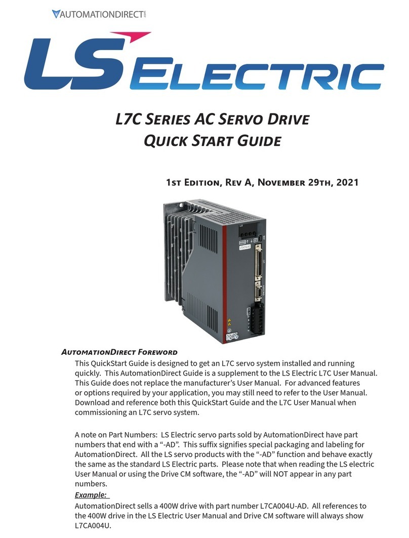
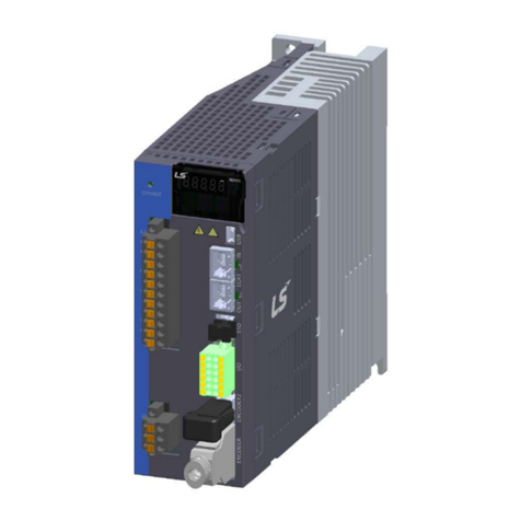
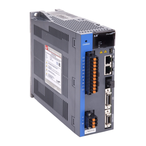
LS ELECTRIC iX7NH Series User manual

iX7NH Series AC Servo Drive
Quick Start Guide
This QuickStart Guide is designed to get an iX7NH servo system installed and running quickly.
This AutomationDirect Guide is a supplement to the LS Electric iX7NH User Manual. This Guide
does not replace the manufacturer’s User Manual. For advanced features or options required
by your application, you may still need to refer to the User Manual. Download and reference
both this QuickStart Guide and the iX7NH User Manual when commissioning an iX7NH servo
system.
This quickstart guide will get your iX7NH drive configured and commissioned using Drive CM.
This is helpful for:
•
For further EtherCAT commissioning help, see AutomationDirect’s LS Electric Interactive PLC
Guide available at https://cdn.automationdirect.com/static/helpfiles/ls_plc/Content/Home.htm
•
For further Modbus TCP commissioning, see the iX7NH Modbus TCP Communications Guide.
A note on Part Numbers: LS Electric servo parts sold by AutomationDirect have part numbers
that end with “-AD”. This suffix signifies special packaging and labeling for AutomationDirect.
All the LS servo products with the “-AD” function and behave exactly the same as the standard
LS Electric parts. Please note that when reading the LS electric User Manual or using the Drive
CM software, the “-AD” will NOT appear in any part numbers. For example, AutomationDirect
part iX7NHA004U-AD is just iX7NHA004U in the LS Electric documentation.
NOTE: EtherCAT®is a registered trademark and patented technology, licensed by Beckhoff
Automation GmbH, Germany.
Modbus TCP

iX7NH Series AC Servo Drives Quick Start Guide
Page 2 of 38iX7NH Servo Drives Quick Start Guide – 1st Edition 12/04/2023
iX7NH Series Servo System Overview . . . . . . . . . . . . . . . . . . . . . . . . . . . . . . . . . . . . 3
Warnings and Cautions . . . . . . . . . . . . . . . . . . . . . . . . . . . . . . . . . . . . . . . . . . . . . . . . 3
Installation . . . . . . . . . . . . . . . . . . . . . . . . . . . . . . . . . . . . . . . . . . . . . . . . . . . 4
Quick Start Instructions . . . . . . . . . . . . . . . . . . . . . . . . . . . . . . . . . . . . . . . . . . . . 5
What you’ll need: . . . . . . . . . . . . . . . . . . . . . . . . . . . . . . . . . . . . . . . . . . . . . . . . . . . 5
First Time Inspection . . . . . . . . . . . . . . . . . . . . . . . . . . . . . . . . . . . . . . . . . . . . . 8
iX7NH Servo Drive . . . . . . . . . . . . . . . . . . . . . . . . . . . . . . . . . . . . . . . . . . . . . . . . . . . 8
APMC and APM Servo Motor. . . . . . . . . . . . . . . . . . . . . . . . . . . . . . . . . . . . . . . . . . . . . 9
Basic Inspection . . . . . . . . . . . . . . . . . . . . . . . . . . . . . . . . . . . . . . . . . . . . . . . 10
System Wiring . . . . . . . . . . . . . . . . . . . . . . . . . . . . . . . . . . . . . . . . . . . . . . . . 11
Pre-made Motor Cables. . . . . . . . . . . . . . . . . . . . . . . . . . . . . . . . . . . . . . . . . . . . . . . 11
Names and Functions of Analog Inputs and Outputs . . . . . . . . . . . . . . . . . . . . . . . . . . . . . . 13
General Wiring Overview . . . . . . . . . . . . . . . . . . . . . . . . . . . . . . . . . . . . . . . . . . . . . . 14
Main Power Connection Wiring . . . . . . . . . . . . . . . . . . . . . . . . . . . . . . . . . . . . . . . . . . 15
I/O Connection Wiring Diagram with Default Functions . . . . . . . . . . . . . . . . . . . . . . . . . . . . . 17
I/O Wiring and Option Details for the Analog Input . . . . . . . . . . . . . . . . . . . . . . . . . . . . . . . 21
LED Display. . . . . . . . . . . . . . . . . . . . . . . . . . . . . . . . . . . . . . . . . . . . . . . . . . 22
Alarms . . . . . . . . . . . . . . . . . . . . . . . . . . . . . . . . . . . . . . . . . . . . . . . . . . . . . . . . 22
Warnings . . . . . . . . . . . . . . . . . . . . . . . . . . . . . . . . . . . . . . . . . . . . . . . . . . . . . . . 22
Drive CM Software. . . . . . . . . . . . . . . . . . . . . . . . . . . . . . . . . . . . . . . . . . . . . . 23
AutomationDirect Foreword . . . . . . . . . . . . . . . . . . . . . . . . . . . . . . . . . . . . . . . . . . . . 23
Getting Started. . . . . . . . . . . . . . . . . . . . . . . . . . . . . . . . . . . . . . . . . . . . . . . . . . . . 23
Using the Drive CM Software . . . . . . . . . . . . . . . . . . . . . . . . . . . . . . . . . . . . . . . . . . . . 25
I/O Configuration . . . . . . . . . . . . . . . . . . . . . . . . . . . . . . . . . . . . . . . . . . . . . . 27
Digital Inputs. . . . . . . . . . . . . . . . . . . . . . . . . . . . . . . . . . . . . . . . . . . . . . . . . . . . . 27
Digital Outputs. . . . . . . . . . . . . . . . . . . . . . . . . . . . . . . . . . . . . . . . . . . . . . . . . . . . 29
I/O Connection - Analog Torque Input . . . . . . . . . . . . . . . . . . . . . . . . . . . . . . . . . . . . . . 30
Setup Wizard. . . . . . . . . . . . . . . . . . . . . . . . . . . . . . . . . . . . . . . . . . . . . . . . . 31

iX7NH Series AC Servo Drives Quick Start Guide
Page 3 of 38iX7NH Servo Drives Quick Start Guide – 1st Edition 12/04/2023
WARNING: Install both the servo drive and the servo motor before performing any
wiring.
WARNING: Before wiring or inspecting, turn off the power, wait 15 minutes, make
sure the charge lamp is off, and check the voltage.
WARNING: Ensure this product is correctly grounded. All grounding and circuit
protection methods must comply with all local standards/regulations and the
national electrical standard (refer to NFPA 70: National Electrical Code, 202 Ed.)
WARNING: Do not change the motor or drive wiring while power is on.
WARNING: Only qualified and trained technicians may perform wiring on this product.
WARNING: Do not operate the servo system with wet hands.
WARNING: Do not open the servo drive cover during operation.
WARNING: Do not operate the servo system with the servo drive cover removed.
WARNING: Do not touch the heat sink of the servo drive when it is connected to
power and operating This component gets very hot and will scald.
CAUTION: The installation location must be free of vapor and corrosive or
flammable gas.
CAUTION: When wiring, do not connect the three-phase power supply to the motor
UVW connectors. Incorrect wiring may cause damage to the servo drive.
CAUTION: Do not disassemble the servo drive.
CAUTION: Verify the emergency stop can be activated before the servo drive is
connected to power and put into operation.
For additional warnings and precautions, please see pages iii through vii of the iX7NH User Manual.

iX7NH Series AC Servo Drives Quick Start Guide
Page 4 of 38iX7NH Servo Drives Quick Start Guide – 1st Edition 12/04/2023
The iX7NH Servo and APM/APMC motors should be installed under the environmental conditions
detailed below. Exceeding these conditions risks damage to the equipment.
Operating Temperature 0–50°C [32–122 °F]
Install a cooling fan on the control panel for
ventilation and to maintain the temperature within the
required range.
Operating Humidity 90% relative humidity or below
Moisture developed inside the drive due to ice
formation or condensation during a prolonged period
of inactivity may damage the drive. If the drive has
been inactive for a prolonged period remove all
moisture before operating the drive.
External Vibration Vibration acceleration 4.9 m/s2
(0.5 G) or lower
Excessive vibration can cause malfunctions and
reduces the lifespan of the drive.
Ambient Conditions
• Do not expose the drive to direct sunlight.
• Do not expose the drive to corrosive or combustible gases.
• Do not expose the drive to oil or dust.
• Ensure that the drive receives sufficient ventilation even if installed in a confined place.
Operating Temperature 0–40°C [32–104 °F]
If motor temperature exceeds 40°C [104 °F], use
forced air cooling to keep the motor temperature
within spec.
Operating Humidity 80% relative humidity or below Do not operate the motors in an environment with
steam.
External Vibration Vibration acceleration 19.6 m/s2
(2.0 G) or lower on X and Y axes
Excessive vibrations reduce the lifespan of the motor
bearings.
Comply with the spacing standard below when installing drives with the control panel:
More
than
10mm
More
than
10mm
More
than
40mm
More
than
40mm
More
than
10mm
More
than
10mm
More
than
100mm
More
than
40mm
More
than
10mm
[1.57 in.]
[1.57 in.]
[1.57 in.]
[0.39 in.] [0.39 in.] [0.39 in.]
[0.39 in.]
[0.39 in.]
[3.93 in.]

iX7NH Series AC Servo Drives Quick Start Guide
Page 5 of 38iX7NH Servo Drives Quick Start Guide – 1st Edition 12/04/2023
To verify your servo components and motor/drive wiring as quickly as possible, please follow the steps
below. These basic instructions will quickly get the motor spinning (verifying that parts and power
wiring are correct).
The rest of this quick start guide contains detailed information on how to properly set up your system
and configure the drive for your specific application.
•
Servo Drive
•
Servo Motor
•
Motor Power Cable
•
Encoder Power Cable
•
Brake Power Cable (for brake-equipped motors)
•
CN6 STO cable (APCS-STOxxA-AD) or STO bypass dongle (APCS-CN6K-AD, included with drive)
•
Drive CM software installed on a Windows PC
•
A USB A to USB mini-B cable (such as SV2-PGM-USB15)
AEnsure Input Power wiring is connected to C1, C2, and Ground. Refer to “Main Power Connection Wiring”
on page 15.
BEnsure 24VDC power and I/O signals are connected. At the very least, make sure the E-Stop and STO
circuits are connected. Refer to “I/O Connection Wiring Diagram with Default Functions” on page 17.
C
Ensure the Motor Encoder cable is connected. Do not simply plug the connector into the motor. Use the
captive screws to ensure the connector is secure. Intermittent encoder connection can wreak havoc with
the system.
D
Ensure the Motor Brake cable is connected (if using a brake motor). If practical, wire the brake directly to
24VDC during initial system testing. This eliminates any question of brake wiring functioning properly.
Brake testing can be verified after initial drive testing.
E
Leave the motor power cable disconnected until initial drive setup and testing are complete to prevent
unwanted motion. Later, the motor will be wired and tested. Do not connect a load to the motor shaft
until testing is completed.
A Turn on 24VDC power to the Drive I/O terminal and brake (if using a brake motor).
B Turn on power (230VAC at L1, L2, L3 (motor power), and C1, C2 (control power)).
C The drive LED display will show the drive’s status and Warning or Alarm codes if present.

iX7NH Series AC Servo Drives Quick Start Guide
Page 6 of 38iX7NH Servo Drives Quick Start Guide – 1st Edition 12/04/2023
AUsing a standard USB A to USB mini-B cable (such as SV2-PGM-USB15, MOSAIC-CSU, etc.), connect the
PC to the Drive.
B Start Drive CM software.
C
Select and press the button. The software should begin to
communicate with the drive. A green flashing square should appear in the bottom left corner of the
screen indicating comms traffic.
Push to
connect
After connecting, icon
will change to this. Push
to disconnect.
A In the Quick Setup window (left side of screen), click .
B
In the USB Connection window, choose and click to read parameters from the drive.
If the radio button is not available and grayed out, click on again. This should
restart the Setup Wizard and enable the button.
C
Follow the steps in the Setup Wizard to define your application.
1) For initial setup and system testing, allow the Setup Wizard to choose the default selections. After
completing this hardware test/verification, you can go through the rest of this guide and refer to the
User Manual if you want to customize your configuration.
2) After stepping through the Setup Wizard, select .
3) After writing to the drive is complete, make sure to cycle power to the drive. A quick way to power
cycle the CPU only is to click the button in the upper right toolbar. Many settings in
the Setup Wizard only take affect after a power cycle.
When writing to the drive and performing a software reset, always make sure the servo is not
enabled.
A Restart the drive and establish communications again.
B
Go to “Fault\Servo Alarm History” and press the button. Correct any errors that are causing alarms
to display on this page. Correction actions and information can be found in the User Manual or by
selecting “Fault\Alarm List.”
C
After fixing any issues, click on and verify the alarms have been corrected.

iX7NH Series AC Servo Drives Quick Start Guide
Page 7 of 38iX7NH Servo Drives Quick Start Guide – 1st Edition 12/04/2023
A Remove power from the drive.
BEnsure that there is nothing attached to the motor shaft. Initial motion testing should always be done
with the motor uncoupled.
C Connect the motor power cable and re-apply power to the drive.
D Reconnect the software to the drive (see Step 3C).
EClick on the icon
F
Enter a nominal speed, acceleration, and deceleration (a value of 200 for each setting is a good starting
point).
If a value is red, that means the value in the drive is different than the value in the software. Click in that
field and press to send the updated value to the drive.
GPress to enable the drive from the software. The drive’s LED should read (servo is in run
mode).
HPress or to jog the motor. Once the motor jogs, you have verified the power wiring,
servo drive, motor, and motor cables are connected properly.
AChoose either an EtherCAT®controller or Modbus TCP to control the system (only one protocol can be
configured).
BThe iX7NH drive can be controlled by EtherCAT or Modbus TCP controllers. Configuration and
Commissioning details can be found in “Setup Wizard” on page 31.
COnce operating mode is set, system quick setup is complete. See the iX7NH Modbus TCP Communication
Guide for further details on Modbus TCP communications.
NOTE: Regardless of using this drive as an EtherCAT or Modbus TCP device, care should be
taken to not have duplicate MAC ID addresses on any network. See the iX7NH Modbus TCP
Communication Guide for more information for the MAC ID.

iX7NH Series AC Servo Drives Quick Start Guide
Page 8 of 38iX7NH Servo Drives Quick Start Guide – 1st Edition 12/04/2023
Ensure your servo motor and drive match capacity.
Part Number Explanation
The three-digit number in
the middle of the drive part
number determines the
power of the drive. Note that
the “-AD” simply represents
special packaging for
AutomationDirect. These are
standard LS Electric parts.
For example:
•
iX7NHAU-AD
•
iX7NHAU-AD
The value 004 represents a
400W drive. The value 010
represents a 1000W (or 1kW)
drive.
1 Display
2 Analog Monitor Connector
3 Node Address Switch
4 Node Address Switch
5 OTG Switch
6 USB Connector (USB, Mini B Type)
7 Main Power Connectors (L1, L2, L3)
8 EtherCAT Input Port (ECAT IN)
9 EtherCAT Output Port (ECAT OUT)
10 DC Reactor Connectors (PO, PI)
11 Safety Connector (STO)
12 Regenerative Resistor Connector (B+, B, BI)
13 Input/Output Signal Connector (I/O)
14 Control Power Terminals (C1, C2)
15 Servo Motor Connection Terminal (U, V, W)
16 Servo Motor Encoder Connector (ENCODER)
17 Ground Terminal
17
1
3
5
10
12
14
15
16
11
9
6
4
2
8
7
13
iX7NHA004U-
AD
115/
230VAC 400W
APMC-FBL01AMK-AD
APMC-FBL02AMK-AD
APMC-FBL04AMK-AD
APMC-FBL01AMK2-AD
APMC-FBL02AMK2-AD
APMC-FBL04AMK2-AD
iX7NHA008U-
AD
230VAC
750W APMC-FCL08AMK-AD APMC-FCL08AMK2-AD
iX7NHA010U-
AD 1kW APMC-FCL10AMK-AD APMC-FCL10AMK2-AD
iX7NHA020U-
AD 2kW
APM-FE15AMK-AD
APM-FE16DMK-AD
APM-FE22DMK-AD
APM-FE15AMK2-AD
APM-FE16DMK2-AD
APM-FE22DMK2-AD
iX7NHA035U-
AD 3.5 kW APM-FF35DMK-AD APM-FF35DMK2-AD
* 100W to 750W 230V motors can use their recommended drives if using a single-phase
supply. No derating required.
1kW 230V motors must be derated to 200% max torque if using 1kW drives with single-
phase input (use the 2kW drive for no derating with single-phase supply).
1.5kW and 1.6kW 230V motors need to be derated to 200% if using the 3.5kW drive with
single-phase supply.
2.2kW 230V motors need to be derated to 150% if using the 3.5kW drive with-single
phase supply.
3.5kW 230V motors can only be used with the 3.5kW drive with three-phase supply.

iX7NH Series AC Servo Drives Quick Start Guide
Page 9 of 38iX7NH Servo Drives Quick Start Guide – 1st Edition 12/04/2023
Part Number Explanation
The motor part number is defined by several of the digits in the middle. Note that the “-AD” simply
represents special packaging for AutomationDirect. These are standard LS Electric Parts.
APM(C)-FxxyyzMK(2)-AD
•
XX = the frame size:
•
BL = 62mm square (80mm bolt circle)
•
CL = 80mm square (105mm bolt circle)
•
E = 130mm square (145mm bolt circle)
•
F = 180mm square (200mm bolt circle)
•
YY = power in hundreds of watts
•
Z = Rated speed 3000rpm if A, 2000rpm if D
•
(2) = If present at the end of the part number,
represents a motor with built-in brake.
No (2) = no brake.
For example:
APM-FE16DMK2-AD
This represents a 230VAC motor, 130mm square, 1.6 kW
power, 2000rpm rated speed, with brake, specially
packaged for AutomationDirect.
Sha
Frame
Housing
Encoder
Connecon
Power
Connecon
FBL/FCL Motors (w/o brake)
2-Pin Brak
(For FBL/FCL brake motors only)
FBL/FCL Braking Motors
Sha
Encoder
Connecon
Power
Connecon
Motor
Connector
Encoder
Connector
Shaft
FE/FF Motors
Note: FE/FF brake motors have brake wiring incorporated into
the power cable (no separate brake cable).

iX7NH Series AC Servo Drives Quick Start Guide
Page 10 of 38iX7NH Servo Drives Quick Start Guide – 1st Edition 12/04/2023
Perform periodic inspections to maintain your equipment, as well as inspections before operation of
the servo and motor.
Periodically check to confirm the screws are securely tightened. This includes the screws in
the servo drive, the connection screws between the motor shaft and the machine, and the
connection screws between the terminal block and machine.
Prevent oil, water, metallic particles, and other foreign matter from entering the control box
or ventilation equipment. Protect the servo drive from any drill cuttings.
If the control box is installed in a location where dust or harmful gas are present, ensure the
dust or harmful gas cannot enter the control box.
Make sure to wire encoders and other devices in the proper sequence to avoid sudden
unintended acceleration or damage to the motor.
To avoid electric shock, connect the ground terminal of the servo drive to the ground
terminal of the control box. If wiring must be added or modified, wait at least 10 minutes
after disconnecting the servo drive from the power supply or discharge the electricity with a
discharge device.
Isolate the wires at the wiring terminal.
Make sure the wiring is correct to avoid damage or any abnormal operation.
Check for and remove any electrically conductive objects, including metal sheet and screws,
or flammable objects inside or near the servo drive.
Make sure the emergency stop switch is OFF.
To ensure the electromagnetic brake works, make sure the stop and circuit breaker functions
are working properly.
Reduce the electromagnetic interference if there is electromagnetic interference with the
peripheral devices.
Make sure the external voltage level of the servo drive is correct.
The encoder cable should be protected from excessive stress – make sure the cable is not
worn or stretched.
Contact AutomationDirect if the servo motor vibrates or makes unusual noise during
operation.
Make sure the parameter settings are correct. Different machines have different
characteristics. Adjust the parameters according to the characteristics of each machine.
Reset the parameters when the servo drive is in the Servo OFF status to avoid possible
malfunction.
If there is no contact noise or other abnormal noise when the relay is operating, contact
AutomationDirect.
Contact AutomationDirect if the power indicator or LED display does not function properly.

iX7NH Series AC Servo Drives Quick Start Guide
Page 11 of 38iX7NH Servo Drives Quick Start Guide – 1st Edition 12/04/2023
Motor connections utilize premade cables available in normal flex or robotic flex specifications. Cables
are available for any iX7NH drive and motor size 100W–3.5 kW but are model dependent (brake cables
are only applicable for brake motors). They are available in lengths of 3m, 5m, 10m, and 20m (9.8 ft,
16.4 ft, 32.8 ft, and 65.6 ft).
For cable model details and specifications, please see www.automationdirect.com.
For assistance in specifying a servo system, go to www.automationdirect.com/selectors for utilities
that will help pick the correct motor, drive, cables, IO components, and accessories.
1
2
3
FG
12
3
FG
Item Phase Pin No.
LEAD
WIRE
U 1
V 2
W 3
FG FG 4
<Front Direction> <Rear Direction>
APCS-PxyyLSX
Motor Side Connector Drive Side Connector
1 7
8 14
Pin
No.
Encoder
Signal
1 -
2 -
3 MA
4 /MA
5 SLO
6 /SLO
7 0V
Pin
No.
Encoder
Signal
8 -
9 -
10 -
11 -
12 -
13 -
14 +5V
Plate SHIELD
Pin
No.
Encoder
Signal
Pin
No.
Encoder
Signal
1 MA 6 /MA
2 SLO 7 /SLO
3 - 8 -
4 0V 9 +5V
5 SHIELD
1
2
3
4
5
6
7
8
9
Motor Side Connector
Drive Side Connector
6
7
8
9
1
2
3
4
5
PIN No.
1
2
BK +
BK -
Signal
Motor SideConnectorDrive Side Connector
Motor Side Connector
Drive Side Connector

iX7NH Series AC Servo Drives Quick Start Guide
Page 12 of 38iX7NH Servo Drives Quick Start Guide – 1st Edition 12/04/2023
Motor Side Connector Drive Side Connector
APCS-L7NCN1T-AD, APCS-L7NCN1T01-AD, APCS-L7NCN1T015-AD, APCS-L7NCN1T02-AD
You can download a printable terminal label (“I/O Breakout Template”) at
https://www.automationdirect.com/pn/APCS-L7NCN1T-AD
See terminal assignments table on the following page.
APCS-CN101A-AD, APCS-CN102A-AD, APCS-CN103A-AD
Connect with:
• L7P-CON-E (for 24-48 AWG pins)
• L7P-CON-F
• L7P-CON-G (for 26AWG IDC)
1 2
3 4
Analog output monitor connection
(viewed from front side of drive)
Connect with:
• APCS-CN6K-AD

iX7NH Series AC Servo Drives Quick Start Guide
Page 13 of 38iX7NH Servo Drives Quick Start Guide – 1st Edition 12/04/2023
3
(A2)
5
(A3)
7
(A4)
9
(A5)
11
(A6)
13
(A7)
15
(A8)
17
(A9)
19
(A10)
4
(B2)
6
(B3)
8
(B4)
10
(B5)
12
(B6)
14
(B7)
16
(B8)
18
(B9)
20
(B10)
1
(A1) 2
(B1)
APCS-L7NCN1Txxx-AD
A1 1 DO1 Yellow Black 1
B1 2 DOCOM Yellow Red 1
A2 3 DO2 Yellow Black 2
B2 4 DO3 Yellow Red 2
A3 5 AGND Yellow Black 3
B3 6 +24V Yellow Red 3
A4 7 DI3 Yellow Black 4
B4 8 DI4 Yellow Red 4
A5 9 AO Yellow Black 5
B5 10 /AO Yellow Red 5
A6 11 DI1 White Black 1
B6 12 DI2 White Red 1
A7 13 DI5 White Black 2
B7 14 DI6 White Red 2
A8 15 A-TLMT White Black 3
B8 16 GND White Red 3
A9 17 ZO White Black 4
B9 18 /ZO White Red 4
A10 19 BO White Black 5
B10 20 /BO White Red 5
AMON1 Analog monitor 1 1 Analog monitor output (-10V to +10V)
1 2
3 4
AMON2 Analog monitor 2 2 Analog monitor output (-10V to +10V)
AGND AGND(0V) 3 Analog ground
AGND AGND(0V) 4 Analog ground
AGND AGND(0V) 5 Analog ground
A-TLMT Analog torque limit 15
-10V to +10V is connected between A-TLMT
(pin 15) and AGND (pin 5) to limit the
motor’s output torque. The relationship
between input voltage and torque limit varies
depending on the Torque Command Scale
[0x221C] value and Torque Limit Function
Select (0x2110).

iX7NH Series AC Servo Drives Quick Start Guide
Page 14 of 38iX7NH Servo Drives Quick Start Guide – 1st Edition 12/04/2023
NOTE: 100W to 2.2 kW 230VAC systems can use a single-phase supply. Any 2 of R,S,T can be
used. See “iX7NH Servo Drive” on page 8 for notes on motor sizes that need derating when
using single-phase power.
U
S
B
ADDR
XGT
5
0
5
0
Power
Three-phase AC 220 V
RS T
Molded-case
Circuit Breaker
It is used to protect power
line.
It turns off the circuit if
overcurrent flows.
3M
10
31
4
3M
10
31
4
POTNOT HOME
DAQ
Mini USB
Cable
Mini USB
Adaptor
Mini USB
Cable
Node Address Setting Switch
Upper Device
Noise Filter
It protects power line
from e xternal noise.
Electromagnetic
Contactor
It turns ON / OF F
servo power.
Safety Device
1.When using an internal
resistor
- Short-circuit (B, BI)
2.When using an external
resistor
- Install (B, B+)
Connect a
regenerative resistor.
Connect DC reactor.
- Short-circuit it if not used
(PO, PI).
1. If the safety function is
not used:
Install the safety jump
connector.
2. If the safety function is
used:
Motor Cable
Safety Cable
Encoder Cable
I/O Cable
EtherCAT Communication Cable
Servo Motor
Servo Drive
Oscilloscope
Analog Monitor Cable
Digital I/O, Encoder Out, Analog In
NOTE: PE between the servo motor and the servo and between the servo and the device must
be connected.

iX7NH Series AC Servo Drives Quick Start Guide
Page 15 of 38iX7NH Servo Drives Quick Start Guide – 1st Edition 12/04/2023
NOTE: Single-phase can use any two wires of R, S, or T. Ensure C1 and C2 are powered as
well.
400W 1-phase 115V/230V, 3-phase 230V
750W–2.2 kW 1-phase (with derating) or 3-phase 230V
3.5 kW 3-phase 230V
Although designed with 3-phase AC input power in mind, some iX7NH systems are capable of
supporting single-phase AC input power. With 3-phase AC supply, the iX7NH motor/drive combination
supplies 300% rated maximum/intermittent motor Torque (see the Instantaneous Operation Range
in the torque-speed charts above). With single-phase AC supply some ratings will have limited
maximum/intermittent torque, and/or the next larger drive size will be required.
100W/200W/400W iX7NHA004U-AD Single phase and three phase input both produce 300% max torque
750W iX7NHA008U-AD Single phase and three phase input both produce 300% max torque
1kW iX7NHA010U-AD or
iX7NHA020U-AD
2kW drive produces 300% max torque. The 1kW drive can be used,
but the motor can only provide 200% max torque.
1.5 kW/1.6 kW/
2.2 kW iX7NHA035U-AD
3.5kW drive produces 200% max torque with 1.5 kW and 1.6 kW
motors. With single phase supply, this drive only produces 150% max
motor torque with a 2.2 kW motor.
3.5 kW n/a No single-phase capability
U
V
W
L1
L2
L3
C1
C2
B+
B
BI
9
11
I / O
RA
M
E
Alarm-
Alarm+
1Ry
RA
1SK
1Ry1MC
+24
V
NF
1MC
R S T
AC 200~230[V]
Main
OFF
PO PI
Servo Drive
DC Reactor
Encoder
Note 2) External
Regenerative
Resistance
3A–5A
Note 1)
Main
ON
NOTE 1: About 1–2 seconds are required from main power supply to alarm signal output. Hold
the main power on for 2 seconds until the alarm circuit (“1Ry”) will latch main power ON.
See “STO Wiring” on page 20.
NOTES 2 & 3: If an external regen resistor is required, see the available regen resistors under
Motion Control category at AutomationDirect.com (APCS-140R50-AD, APCS-300R30-AD, etc.).
Remove the jumper from the internal resistor between B and BI, and connect the external
resistor to the B+ and B pins.

iX7NH Series AC Servo Drives Quick Start Guide
Page 16 of 38iX7NH Servo Drives Quick Start Guide – 1st Edition 12/04/2023
NOTE: To connect a power or motor connector, use the provided spring cage release tool (IX7-
CON-C) or flat-head screwdriver to clear the opening as shown below. Insert the core wire
into the hole and pull out the spring opener or flat-head screwdriver to complete connection.
Wiring Specifications
15A 30A
TB6-B010LBEI (10A) TB6-B030NBDC (30A)
10A 15A 30A
11A / 240V 18A / 240V 32A / 240V
1
16AWG
(1.5 mm2)
14AWG
(2.5 mm2)
12AWG
(4.0 mm2)
AL 1, 5-8 BK 3200043, Phoenix Contact
AI 0, 75-8 GY-3200519, Phoenix
Contact
(8.5 ± 0.5 mm strip & twist)
UA-F4010, SEOIL
(10mm strip & twist)
50W
100Ω
100W
40Ω
150W
13Ω
iX7-CON-A
iX7-CON-B
iX7-CON-C
iX7-CON-D
iX7-CON-E
iX7-CON-F
- Select and use 600V, PVC-insulated wires. To comply with UL (CSA) standards, use UL-certified wires that have a
heat resistant temperature of 75°C [167°F] or above. To comply with other standards, use proper wires that meet the
applicable standards. For other special specifications, use wires equivalent or superior to those specified in this section.
- Use Class CC or High Speed J (HL series) current limiting fuses to prevent nuisance tripping and to increase the panel
SCCR rating.
Power Connector Signal Names
L1
Main power connectors
L2
L3
NNeutral from incoming 3-phase power supply
P0 DC reactor connection connector
PI
B+
Recovery resistance connection connector
B
BI
C1 Control power terminal
C2
U
Servo motor connection terminal
V
W
NOTE: Strip all Power Connector wiring 7–10mm. Refer to section 3.4.2 of the User Manual.

iX7NH Series AC Servo Drives Quick Start Guide
Page 17 of 38iX7NH Servo Drives Quick Start Guide – 1st Edition 12/04/2023
I/O Connection wiring diagram is shown below. For a printable terminal label, go to:
https://www.automationdirect.com/pn/APCS-L7NCN1T-AD.
See “Terminal Assignments and Wire Colors” on page 13 for terminal assignments.
POT 11
NOT 12
HOME 7
STOP 8
PCON 13
GAIN2 14
PCL
NCL
BRAKE1
ALARM3
6+24V IN
DC 24V
3.3kΩ
TLMT**
INPOS1**
(DI1)
(DI2)
(DI3)
(DI4)
(DI5)
(DI6)
(DO1)
(DO2)
VLMT**
READY4
DOCOM2
(DO3)
ZSPD
I/O
STO
STO1+ 4
3STO1-
STO2+ 6
5STO2-
EDM+7
EDM-8
PROBE2
PROBE1
EMG
**
**
**
A-RST **
WARN**
INSPD**
TGON**
INPOS2**
3.3kΩ
3.3kΩ
Analog
Monitor
MONITOR 11
-10V ~+ V
10
MONITOR 22
AGND3, 4
-10V ~+
10V
A-TLMT 15
Analog input
AGND 5
Analog
torque limit
LVSF1 **
LVSF2 **
SVON **
ABS-RESET **
ABS-RQ **
AO9
BO19
GND16
**
**
**
/AO10
/BO20
ZO17
/ZO18
Upper level controller
Digital Input Digital Output
Safety Function InputSafety Function Output
Analog Output
R
Br
DO Com
Interposing
relay
Do not wire the brake
output directly to the brake.
Use an interposing relay.
Brake coil is not polarity
sensitive (use either lead
for + or -)
Motor Brake
+24VDC
Analog monitor wiring
viewed from front side
of the drive. See
L7P-CON-F and
L7P-CON-G for
connector options.
See STO Wiring section
on page 20 for example
wiring.
NOTE: Input signals DI1–DI6 and output signals DO1–DO3 are factory default signals and can be
reconfigured.
NOTE: APCS-L7NCN1Txxx-AD provides shielding between the servo and the terminal blocks.
User provided shielding should be installed for high speed and analog signals (ground the
shield on the PLC side).

iX7NH Series AC Servo Drives Quick Start Guide
Page 18 of 38iX7NH Servo Drives Quick Start Guide – 1st Edition 12/04/2023
The iX7NH includes a Modbus TCP Server feature. For Modbus TCP
communications to the drive the two rotary dials need to be addressed to
node 98 or 99. Node 99 allows access to the built-in webserver in the drive. For
network installations that do not allow webservers, Node 98 enables Modbus
TCP communications without the built-in webserver function (firmware version
1.15 and later). See the iX7NH Modbus TCP Communication Guide for further
details on Modbus TCP communication.
Note that the drive only reads the node switch value when power is turned on. To change the value,
the power has to be turned off and back on again.
Modbus TCP communication is only available using the EtherCAT-IN port.
The iX7NH supports the following operation modes (0x6060) when connected to the Modbus-TCP
server.
•
Profile Position Mode (PP): Refer to Section 5.3.2
•
Homing Mode (HM): Refer to Section 5.6
•
Profile Velocity Mode (PV): Refer to Section 5.4.2
•
Profile Torque Mode (PT): Refer to Section 5.5.2
Default IP Address : 192.168.5.5 / Port : 502
See section 13.1 in the iX7NH user manual for further details.
The iX7NH Node address must be unique on an EtherCAT network. For EtherCAT usage, set the two
rotary dials to any value 0 - 97 not being used on the network.
NOTE: The iX7NH MAC ID factory default setting is 00:00:00:00:00:00 for all drives
(parameter 0x241F). Having duplicate MAC IDs will probably not impact an EtherCAT network,
but care should be taken to avoid having duplicate MAC IDs on any managed network. See the
iX7NH Modbus TCP Communication Guide for more information.
Digital Inputs
1) You can set the input contact to contact A (normally open) or contact B (normally closed).
2) You can assign each input contact to one of 17 functions.
3) For more information on signal assignment and change of the input contact, refer to the User
Manual, section 6.2 “Input/Output Signals Setting.” The Drive CM software makes setting the I/O
signals very quick and easy.
4) The rated voltage is 12VDC to 24VDC.
Internal
circuit
R2
R1
Internal
circuit
R2
R1
DI1
Servo drive
External Power Supply
12 VDC to 24 VDC
+24V IN
R1: 2.49KΩ, R2: 680Ω
DI6

iX7NH Series AC Servo Drives Quick Start Guide
Page 19 of 38iX7NH Servo Drives Quick Start Guide – 1st Edition 12/04/2023
Digital Outputs
1) You can set the output to contact A (normally open) or Contact B (normally closed).
2) You can assign each output contact to one of 11 output functions.
3) For more information on signal assignment and change of the output contact, refer to the User
Manual, section 6.2 “Input/Output Signals Setting.” The Drive CM software makes setting the I/O
signals very quick and easy.
4) Excessive voltage or overcurrent may damage the device because it uses an internal transistor
switch. Be cautious. Do not directly power large inductive loads, use an interposing relay.
5) The rated voltage and current are 24VDC ±10% and 120mA.
DC 24V
L
L
DO3
내부
회로
내부
회로
DO1
서보드라이브
DOCOM
DOCOM
Inner
Circuit
Inner
Circuit
Servo Drive
6) When using an electronic brake, refer to the wiring diagram below for configuration.
Servo Drive
BRAKE
DOCOM
RA1 BK+
SK
RA1
BK-
BRAKE
Servo motor
DC24V DC24V
Note
NOTE: Use separate power sources for the control and the main power of the electronic brake
with voltage according to the electronic brake’s specifications (refer to “Electronic Brake
Specifications” table in iX7NH User Manual Section 2). For DO1-DO3 output, use a common
GND24 for DOCOM.

iX7NH Series AC Servo Drives Quick Start Guide
Page 20 of 38iX7NH Servo Drives Quick Start Guide – 1st Edition 12/04/2023
The iX7NHA Safe Torque Off circuit is designed to meet Safety Category 3, Safety integrity level 2 (SIL
2), Performance level d(PL d).
ESTOP
4
3
6
5
7
8
STO1+
STO1-
STO2+
STO2-
EDM+
EDM-
STO
24VDC
Safety relay
(Example of automatic reset
with a Dold LG5925
safety relay)
S11 S12 S21 S22 13 23
S34 S33 14 24
Current flow
NOTE: Polarity between terminals
S33/S34 and EDM+/- must be correct.
If polarity is reversed, enough leakage
current will ow thru the drive transis-
tor to satisfy the reset circuit of the
safety relay.
1. The STO rated voltage is 12VDC to 24VDC
2. With the contacts of STO1 and STO2 o, the
motor output current is blocked.
NOTE: Each iX7NH drive ships with an STO bypass connector APCS-CN6K for commissioning
and testing. AutomationDirect recommends using pre-made STO cables (APCS-STOxxA-AD) to
facilitate STO wiring.
This manual suits for next models
5
Table of contents
Other LS ELECTRIC Servo Drive manuals
Popular Servo Drive manuals by other brands

SSD Drives
SSD Drives 637 product manual

Smitec
Smitec COSMOS 301 Series Installation, use and maintenance manual

National Instruments
National Instruments NI 9502 Getting started

Panasonic
Panasonic MINAS A5E Series operating instructions

Astor
Astor Astraada SRV-63 series Operation manual

Mitsubishi Electric
Mitsubishi Electric MR-J4-10A(-RJ) instruction manual