Page 2
Power Guard Operator Manual Version 1.3 May 2007
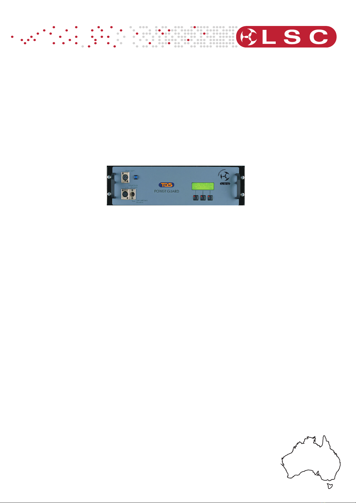
1.0 Product Information
The PowerGuard power monitoring system is a microprocessor based 3 phase mains
power supervisor. The PowerGuard will analyse the voltage and current parameters of
each phase of the incoming mains power, as well as measure the line frequency. An
additional function for the PowerGuard is to monitor the temperature of the dimmer
racks, when fitted into the TDS Dimming System.
A comprehensive menu system gives the user maximum system information within the
shortest time. The main menu displays the current system status, showing all line
voltages and currents as well as the rack temperature and line frequency. By “digging”
a bit further, statistics for maximum and minimum Voltages, Currents and Temperatures
are displayed along with the exact times that these peaks or lows occurred. A further
menu allows the setting of the real time internal clock. Statistical information will
accumulate over time or can be reset or cleared if desired. An integral LED backlight in
the display, makes reading the display easier. The backlight switches itself off after 5
minutes if no buttons have been pressed. More information on the menu system can be
found in section 4.1 “PowerGuard Operation”.
The voltages and currents measured are read as true RMS values. True RMS is the
component of an AC waveform that actually contains energy to do work. ie the mains
from a wall socket in Australia is 240VAC RMS. The peak voltage of this waveform is
339Volts. However an analysis of the waveform will yield that only an average of the
components of the waveform are actually used to do work, such as heating a light bulb
filament. In pure AC applications where full sine waves are used the RMS and Peak
values can be readily calculated. But in phase control AC dimming systems, the mains
waveform is severely chopped up so a simple calculation is no longer applicable. LSC
use specific circuitry and software to read the true RMS values from its power sensors.