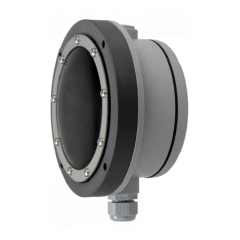
Mollet MFB User manual

M LLET
Füllstandtechnik
GmbH
Manufacturer MOLLET
and vessels. It can be used as full, demand and empty indicator for
Address Industriepark RIO 103
Füllstandtechnik GmbH
74706 Osterburken
Name Membrane level indicator
Operating instructions
1.1 Intended use
The level indicator observes the filling level as a limit switch in silos
dusty and powdery, granulated and grainy bulk goods with a max.
1. Description
grain size up to 100 mm and with a bulk density of 0.3 t/m³... 2.5 t/m³.
1.2 Function
The bulk goods presses with its weight against the membrane.
A tappet directly transfers the pressure from the membrane to the
switch. When the bulk goods are decreasing, pressure is taken off
the membrane and the switch will be interconnected.
1.3 Technical data
Type MFB
acc. to DIN EN 60529 IP53 if cable gland is downwards
Stainless steel 304 -20 °C ... +200 °C
IP65 with stainless steel membrane
Mounting position any position
Switching voltage 24 V ... 250 V AC
Maintenance none
Signal contact change-over contact, potentialfree
Weight 1.85 kg
Capacity of the contact 4 A / 250 V AC
or 12 V ... 125 V DC
Overpressure safety up to 5 bar
Ambient temperature -20 °C ... +80 °C
Bulk goods NBR -20 °C ... +80 °C
temperature VITON -20 °C ... +150 °C
Cable entry Cable gland M20x1.5
Response delay none
Cable connection Scrwe M4 for cable socket
Type of protection IP40
1.4 Dimensions
4. A fuse (with max. 4A) has to be connected in series to the voltage supply.
2. Comply with the local and statutory rules and regulations and/or the VDE 0100.
Safety instructions
1. The installation, initial operation and maintenance may be done by a qualified expert with electrical know-how only.
3. Take notice of the temperature specifications at the data plate.
6. The device may put into operation if it is closed, only.
7. Switch off the power supply, before opening the device. (touchdangerous voltage)
5. Protect the signal contact from voltage peaks when inductive loads are connected.
Read and follow these safety instructions first and take notice of the operating instructions.
MOLLET D-74706 Osterburken Tel. +49 6291 6440-0 Fax +49 6291 9846 Operating instructions
top
002-0205
60
Ø 187
214
200
5 x 72°
7
Ta
Ts
Contact
IP
Housing Aluminium
Type Membrane Mounting ring
MFB-NE = NBR Stainless steel 1.4301 / 304
MFB-VA = VITON Aluminium
1.5 Materials
MFB-NA = NBR Aluminium
MFB-VE = VITON Stainless steel 1.4301 / 304
MFB-EA = Stainless steel 304 Aluminium
MFB-EE = Stainless steel 304 Stainless steel 1.4301 / 304
14
4
Ø 110
M20x1.5
Membrane level indicator
MFB
02/20 © by MOLLET MFB-BA 01
Contact
see Type plate
see Type plate
max. Switching voltage
max. Braking capacity
02/20 © by MOLLET MFB-BAD 01
By use in explosive hazardous areas read and follow the
MFB-B0
for safe application
first and take notice of the operating instructions.
special conditions and instructions
attached
B0

[
2.2 Mounting in the vessel
instructions, before handling with the device !
2. Installation
- Check the membrane of visual transport damage.
and fix it with 5 washers and screws M6.
Position the level indicator with the gasket at the provided flange
Circuit diagram
2.3 Electrical connection
- Read and follow the safety instructions and the operating
2.1 Preparation
- The level indicator is presetted at sensitive.
- Put the level indicator into operation only, if the installation and the
NBR 100 g ... 200 g
-
Clockwise insensitive.
VITON 100 g ... 200 g
- After electrical connection, tighten the cable gland.
Stainless steel 1.4301 / 304 200 g ... 500 g
- Screw the cap nut, until the cable entry is closed tightly.
electrical connection have been done correctly.
- Sensitivities with membrane:
- With the adjusting nut the device can be adjustable insensitive.
2.4 Cable gland
3. Commissioning
M LLET
Füllstandtechnik
GmbH
02 MFB-BAD 01/19 © by MOLLET
Operating instruction MOLLET D-74706 Osterburken Tel. +49 6291 6440-0 Fax +49 6291 9846
4.1 Normal operation
of bulk goods was exceeded or was fallen short off.
4.2 Inexpert handling
- Ignoring of the safety instructions and the operating instructions.
4. Utilization
- Damaged devices have to put out of operation immediately.
- Mounting of spare parts which are no original parts.
- Violation against applicable law and standards.
-
- Use the level indicator in its intended application only.
- Not intended use.
pressureless operation.
- The level indicator is provided for use in silos or vessels with
- Comply with the specifications on the data plate. Check the
membrane of the level indicator, when the permissible temperature
if there is no overpressure or vacuum.
5.2 Maintenance
5.3 Servicing
- Store the level indicator dry and dust-free.
radiation.
- Damaged parts have immediately replaced with similar.
-
7. Disposal
according to the location of the carrier and the local manufacturing
- Protect the membrane against pointed objects and ultraviolet
conditions.
immediately with a new membrane.
5. Maintenance and servicing
membrane. Define the control intervals, depending on the
characteristics of the bulk goods.
6. Storage
- Inspect in regular intervals if there is any wear or abrasion at the
-
- The disposal applies to the valid environmental guidelines
- The level indicator can be recycled.
- In case of damage or abrasion, replace the membrane
- Until the complete reconstruction of the proper function, the level
- Use original spare parts only.
indicator must not be used any more.
5.1 General informations
- Do maintenance work only, if the silo or the vessel is empty and
-
PE
NC NO C
P
23/4 1
12 3/4
002-AP01
adjusting nut
Membrane level indicator
MFB

MOLLET D-74706 Osterburken Tel. +49 6291 6440-0 Fax +49 6291 9846
01/20 © by MOLLET MFB-SH-01 03
M LLET
Füllstandtechnik
GmbH
Explosion protection information
Membrane level indicator
MFB
Special conditions and instructions for safe application
15. Clean the device with a moist towel only. Don´t use any pointed objects or solvents.
14. Take notice of the requirements of DIN EN 60079-14, DIN EN 60079-17 and DIN EN 1127-1, especially regarding the dust deposits and
temperatures and follow the pertinent rules and regulations.
12. Switch off the power supply, before opening the device. (touchdangerous voltage)
13. Depending on the bulk goods characteristics and the wear, the carrier has to define resp. to find out in which intervals the membrane of
the level indicator has to be checked for leakage to keep the type of protection (Dust-proof). This inspection has to be repeated regularly.
with a torsional force of 3.75 Nm.
11. The device may put into operation with built-in cap-sealing and when it is closed, only.
cable has to be brought into the cable gland.
If there is a fault, the membrane has to be replaced with a new membrane.
6. As soon as the device will be brought into the explosion hazardous area it has to be mounted immediately at the precaused place and a
5. Protect the signal contact from voltage peaks when inductive loads are connected.
8. Please check if the cable gland have loosened during on the mounting or at the transport. When it is loosened, it has to be fitted again
7. Using the device in ambient temperatures > +60 °C, the applied connection cables have to be made for temperatures of min. +80 °C.
9. To secure the type of protection, the screw nut of the cable gland has to be fixed at the installation with a torsional force of min. 2.7 Nm.
If it will be fastened too strong, the IP-protection can be affected.ATTENTION!
10. The earth connection of the device has to be installed in such a way that mechanical damage will be excluded.
2. Comply with the local and statutory requirements and/or the VDE 0100.
4. A fuse (with max. 4A) has to be connected in series to the voltage supply.
1. The installation, maintenance, initial operation, removal and repair have to be controlled resp. checked by an “authorized person” for
3. Take notice of the temperature specifications at the data plate.
explosion protection.
-

M LLET
Füllstandtechnik
GmbH
Single parts MOLLET D-74706 Osterburken Tel. +49 6291 6440-0 Fax +49 6291 9846
04 MFB-ET-01 04/13 © by MOLLET
2 Switch Z-15G-B
8 Mounting ring . E MFB-HR-VA Stainless steel 304
Mounting ring . A MFB-HR-AL Aluminium
Item Reference Order code Material
6 Membrane E . MFB-MB-VA Stainless steel 304
4 Spring MFB-FR01 Spring steel
9 Gasket MFB-FD01 NBR foam
1 Cap seal MFB-DS01 EDPM
3 Filter 395028-AVS Brass
7 Seal ring MFB-DS02
10 Spare part kit incl. switch for MFB-E . MFB-EP11
Membrane level indicator
Single parts
MFB
1
3
7
4
986
2
10
002-0803
M20x1,5

L
L
E
O
T
M
-
-
F
n
ü
e
l
l
k
s
r
t
a
u
n
b
r
d
e
t
t
e
s
c
h
O
n
6
i
k
0
7
G
4
m
7
-
b
D
H
H
ExB
Wolfgang Hageleit
Geschäftsführer / Managing director
EU-Konformitätserklärung
EU-Declaration of Conformity
Wir/We MOLLET Füllstandtechnik GmbH
Industriepark RIO 103
D-74706 Osterburken
Tel. 06291 64400 Fax 06291 9846
erklären in alleiniger Verantwortung, dass das Produkt:
declares under our sole responsibility, that the product:
Membran-Füllstand-Grenzschalter / Membrane limit switch
Membran-Füllstandanzeiger / Membrane level indicator
Typ/Type MFA ... , MFB ... und/and MFD ...
den folgenden Europäischen Richtlinien entspricht:
conforms with the following European directives:
Niederspannungsrichtlinie Low voltage directive 2014/35/EU
Angewandte harmonisierte Normen oder normative Dokumente:
Applied harmonized standards or normative documents:
DIN EN 61010-1:2020 DIN EN 60529:2014
Und die Geräte mit W - Kennzeichnung entsprechen zusätzlich der folgenden Europäischen Richtlinie:
And the devices with W - marking conform additional with the following European directive:
ATEX-Richtlinie ATEX directive 2014/34/EU
Angewandte harmonisierte Normen oder normative Dokumente:
Applied harmonized standards or normative documents:
DIN EN IEC 60079-0:2019 DIN EN 60079-31:2014
Prüfprotokollnummer:
test report number: ATEX-PP-06-917
Qualitätssicherung:
Quality assurance: TÜV NORD CERT GmbH, 30159 Hannover (0044)
Osterburken, den 15.11.2021
EUKE-MF
M LLET
Füllstandtechnik
GmbH
Diese Erklärung darf nur unverändert weiterverbreitet werden.
This declaration is only allowed to hand out in unchanged form.
91_EUKE-MF_2_11-21
Index 2
Seite/Page 1 von/of 1
Table of contents
Other Mollet Measuring Instrument manuals

Mollet
Mollet PF User manual

Mollet
Mollet LF20 Series User manual

Mollet
Mollet DF Series User manual

Mollet
Mollet MOLOS MFD User manual

Mollet
Mollet MOLOSwave MWF2 Series User manual

Mollet
Mollet MSD-420 User manual

Mollet
Mollet LF20 Series User manual

Mollet
Mollet MOLOSwave MWF2-KIT Parts list manual

Mollet
Mollet MOLOS membran MFA Series Installation instructions

Mollet
Mollet SES User manual