LSC MDR Series User manual

DMX512-A & RDM Compatible
Data Splitters
Operator Manual
Document Number: MDR-T0U-A1.doc
Version: 1.1
LSC Lighting Systems (Aust) Pty. Ltd.
ABN 21 090 801 675
Building 3, 66-74 Micro Circuit
Dandenong South, Victoria 3175 Australia
Tel: +61 3 9702 8000
Fax: +61 3 9702 8466
web: www.lsclighting.com


MDR DMX512/RDM Data Splitter Operator Manual
LSC Lighting Systems (Aust) Pty Ltd.
Page 1
Introduction
DMX512-A based data splitters are not new to LSC. From the Company’s involvement in
developing the original DMX512 specification in 1986, to releasing a number of “world’s
first” DMX512 based products in the ensuing years, LSC has been at the forefront of
DMX512 communication for the entertainment industry.
The MDR range continues this pedigree with the introduction of feature-upgradeable
splitters to incorporate the latest developments in DMX512 communication –namely, RDM
and Wireless DMX512. The MDR range is Future-Proofed allowing the add-on of RDM
(Remote Device Management) and wireless DMX512 receivers from Wireless Solutions (W-
DMX) and City Theatrical (SHoW DMX), when you need it.
The range encompasses a 5-way and 10-way 19” Rack Mount configuration as well as a 5-
way portable version that can be truss mounted as well as used free standing. The two 5-
way versions allow the option of adding both RDM and Wireless DMX modules, whereas the
10-way only allows the addition of RDM as an option. Additionally an installation version
comprising all RJ45 style connectors is available. Refer to the model range below for part
numbers. All options are field upgradeable, meaning that with a basic screwdriver, you can
add the plug-in options to existing units.
This Operator Manual will give you a brief overview of the products and their key features,
how to connect and operate the splitters and then an explanation of DMX512-A and RDM.
MDR 5 way Rack mount
with RDM and Wireless
DMX option fitted.
MDR 5 way Truss mount
shown with supplied
Velcro straps fitted
MDR 10 way Rack
mount with RDM option
fitted.
MDRJ 10 way
RJ45 Rack
Mount

MDR DMX512/RDM Data Splitter Operator Manual
Page 2
LSC Lighting Systems (Aust) Pty Ltd.
Getting Connected
For the purpose of this section only the MDRT Portable 5-way model is shown with all
options fitted. Please note that the MDRX 10-way model cannot have the Wireless DMX512
option fitted.
Truss Mounting
The MDRT splitters can be mounted to truss, handrails and pipes using two methods. The
first method is with two Velcro straps, supplied with the splitter that can be looped through
the end cavities of the plastic housing and wrapped around the truss or pipe.
The second method is a factory supplied option, consisting of a metal bracket and fixing
bolts, that allows the splitter to have a coupler or hook clamp attached.
For either method it is recommended to feed a suitably rated safety wire/chain through the
end cavities of the splitter and fasten around the pipe/truss/handrail.
Fuseholder
0.5 Amp
rated fuse.
Recessed cavity
for storing aerial
when not in use.
Standard
IEC input
connector
Optional
Powercon
input.
RDM
Priority
LED
Curved End
pieces for
fastening to
truss pipe
DMX512
Output
Connectors
DMX512
Priority
LED
RDM
Enable
Switch
End-of-Line
DMX512
Termination
Switch & LED
DMX512
Pass-Thru
Connector
DMX512
Input
Connector
MDR
Status
LEDs
Supplied
Velcro
Straps
Optional
Clamp
Bracket

MDR DMX512/RDM Data Splitter Operator Manual
LSC Lighting Systems (Aust) Pty Ltd.
Page 3
DMX512 Operation
The MDR DMX512 data splitters have been designed for quick and easy operation. A brief
operational instruction is detailed below.
1. Connect the MDR DMX512-A data splitter to a suitable power source and apply power.
The “POWER” light will illuminate.
2. Connect the DMX512-A source cable into the DMX INPUT connector of the MDR splitter.
The “DMX data” light next to the connector will illuminate if data is present.
3. If the MDR splitter is to be the last device at the end of the DMX512 input cable, then
press the DMX TERM button. The “DMX Terminate” indicator light will now illuminate.
4. If the MDR splitter is not the last device on the line, the DMX THRU output connector
can be used to connect an output cable and allow the incoming data stream to continue
to other equipment downstream.
5. Connect the required DMX512 output cable/s to the DMX512 output connectors of the
MDR splitter.
6. DMX512-A data present at the DMX512 input connector is now internally routed to all
five (ten) DMX512 output connectors and therefore to all devices connected downstream
from the MDR splitter.
Note: All outputs are individually isolated from each other as well as the input. Isolation is
for both data and common connections and provides a galvanic barrier to 1500 Volts.
Outputs are EMI filtered and current limited to protect against short circuits.
RDM Operation
The RDM module, when fitted, allows RDM based devices to communicate with each other in
bi-directional mode interleaved with the DMX512-A signal. All Inputs and Outputs use the
standard DMX512-A connectors and cables.
1. Connect Power, Input, Thru and Outputs as per the DMX512 section above.
2. To make the MDR splitter work in RDM mode, press the RDM Enable switch. The RDM
Enable indicator light will now illuminate.
3. When data passes through the MDR splitter from the controller to a responder, then the
DMX DATA >indicator will illuminate. When RDM data passes back through the splitter
from the responder to the controller, then the RDM DATA <indicator will illuminate. As
RDM is bi-directional, it is possible that both indicators may illuminate at the same time.
4. If RDM data overflows, the RDM ENABLE indicator will begin flashing and the RDM
function will be disabled automatically.
Note: When an RDM device overflows the RDM data stream, then you must isolate the
offending device from the network and reset the RDM module in the MDR splitter by
pressing the RDM ENABLE switch off, then back on.

MDR DMX512/RDM Data Splitter Operator Manual
Page 4
LSC Lighting Systems (Aust) Pty Ltd.
Wireless DMX512 Operation
For full wireless DMX512-A operation, please refer the manufacturer’s websites:
Wireless Solutions (W-DMX) www.wirelessdmx.com
City Theatrical (SHoW DMX) www.citytheatrical.com
The Wireless DMX512 modules supplied by LSC for the MDR range of splitters are modified
receiver boards from the manufacturers listed above.
LSC do not supply wireless DMX512 transmitters. Please contact the above manufacturers
for the appropriate transmitter to work with the MDR splitter.
The Wireless DMX512 module can work as a sole DMX512-A input source for the splitter or
as a back-up source to the cable input, thus providing full redundancy for the DMX512-A
cable input. If both Wireless DMX512 and cable DMX512 are both receiving data, the cable
DMX512 input has priority. However, if there is a failure on the cable DMX512 input, the
MDR splitter has an Auto-Switching feature that seamlessly switches the input priority to
the Wireless input. When the failure on the cable DMX512 input has been rectified, the MDR
splitter will automatically switch back to the cable DMX512 input.
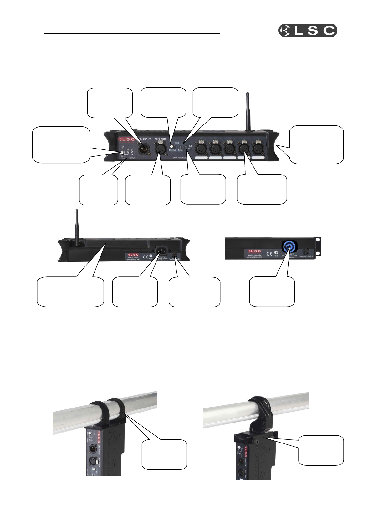
1. Connect Power, Input (if required), Thru (if required) and Outputs as per the DMX512
section above.
2. For Wireless Solutions W-DMX models, press and release the FUNCTION button to
synchronise the receiver to the transmitter device. This process may take up to 10
seconds to synchronise. Once synchronised the STATUS indicator will illuminate.
3. To unlink the receiver from the transmitter, press and hold the FUNCTION button until
the Status indicator goes off. The receiver is now not linked to the transmitter.
4. For City Theatrical SHoW DMX models, there are two buttons, a display and a Status
indicator. The display shows 4 menu choices, various settings and unit information. The
display will timeout after 10 seconds if no button activity is detected. The left and right
buttons are used to move through the menus and to adjust and select settings. The
Status indicator blinks Red to indicate operation and No Transmitter Detected, and
blinks Green to indicate operation and Transmitter Detected.
5. To set the receiver to respond to the SHoW DMX transmitter, you must select one of 64
different SHoW ID’s that corresponds to what the transmitter is set to. Press the MENU
button to activate the display. The display will show the current ID: IDxx. Press the
SELECT button to scroll to the required ID number. The STATUS indicator will blink
Green to indicate the receiver has synchronised to the transmitter.
6. The SHoW DMX also allows you to change the Power setting. You will not need to
change the setting as this will be set by LSC prior to the unit leaving the factory.

MDR DMX512/RDM Data Splitter Operator Manual
LSC Lighting Systems (Aust) Pty Ltd.
Page 5
DMX512 Explained
DMX512-A is the industry standard for the transmission of digital control signals between
lighting equipment. It utilises just a single pair of wires on which is transmitted the level
information for the control of up to 512 DMX slots (addresses or channels).
The information for each slot is sent sequentially. The level of slot 1 is transmitted, then the
level of slot 2, then 3, etc. up to a maximum of 512 slots. This stream of data containing
the levels for all 512 DMX slots is repeated a minimum (generally) of 44 times per second.
This provides sufficient updates of channel information for smooth fade transitions.
As the DMX512-A signal contains the level information for all slots, each piece of equipment
needs to be able to read the level(s) of the slots(s) that apply only to that piece of
equipment.
DMX512 Cables
When good quality data cables are used, DMX512 cable runs may be up to 1,000 metres in
length. When several DMX streams are required (to feed different locations), DMX512
splitters must be used. These provide multiple isolated DMX512 output streams of the same
input stream.
Note: Do not use unscreened microphone or low speed data cables for DMX. This can cause
problems in the DMX network. Make sure the cable conforms to the EIA485 cable
requirements by providing the following specifications:
Low capacitance
One or more twisted pairs
Foil and braid shielded
Impedance of 85 -150 Ohms, nominally 120 Ohms
22AWG gauge for continuous lengths over 300 metres
DMX512 Connector pin assignments
Connector pin
number
XLR 5-pin input
connector
XLR 5-pin thru
connector
XLR 5-pin
output
connectors
XLR 3-pin
output
connectors
Pin 1
Common
Common
Ground
Ground
Pin 2
DMX –ve in
DMX –ve thru
DMX –ve out
DMX –ve out
Pin 3
DMX +ve in
DMX +ve thru
DMX +ve out
DMX +ve out
Pin 4
Looped through
Looped through
Looped through
Not used
Pin 5
Looped through
Looped through
Looped through
Not used
RJ45 DMX Connector pin assignments
Connector pin number
RJ45 8-pin connector
Pin 1
DMX +ve
Pin 2
DMX –ve
Pin 3
Not Connected
Pin 4
Not Connected
Pin 5
Not Connected
Pin 6
Not Connected
Pin 7
Common
Pin 8
Common

MDR DMX512/RDM Data Splitter Operator Manual
Page 6
LSC Lighting Systems (Aust) Pty Ltd.
RDM Explained
RDM is an acronym for Remote Device Management which is a relatively new protocol that
overlays on the existing DMX512-A cable network, using the same 3-pins of the XLR
connector. The protocol has been released under the standard ANSI-E1.20-2006. Equipment
connected to the DMX512-A network wishing to use the advantages of RDM, must be RDM
compatible.
Unlike DMX512-A, RDM is bi-directional –meaning messages sent out can be responded to
and reported back to the originator. This can allow RDM controllers to interrogate, control
and report on any RDM enabled devices on the network, by:
changing DMX start addresses
reporting faults
changing fixture mode settings
requesting a list of fade curves available from a dimmer rack
report on lamp hours usage per fixture
temperature reporting of dimmers and other connected devices
and so on…..
RDM will allow a lighting console to discover all the devices connected to its outputs and
even to know how many DMX slots each item requires. This information could then be used
to auto-patch the entire rig. The user settings of all the devices could be saved as part of
the show file, so that when the show is re-loaded into the console, the system could ensure
that all devices are still connected and working, then check that the Pan invert settings and
custom dimmer curves on certain devices have not changed. In the case of a faulty moving
light, a new light could be connected and the user settings (eg. DMX address, mode, Tilt
invert) automatically uploaded to the new unit.
RDM is backwards compatible with existing DMX512 equipment, allowing non RDM devices
to be connected to the same cable as RDM devices. The non-RDM units, if fully conforming
to the DMX512-A standard, will simply ignore all the RDM data. The only exception to the
rule is DMX512-A data splitters. Non RDM units will simple block (stop) all RDM data from
any devices connected downstream of the DMX512-A splitter. Therefore any lighting system
using RDM must use RDM enabled DMX512-A data splitters.
Once the uptake of RDM by other manufacturers reaches levels where the majority of
equipment is RDM compatible, the advantages of RDM will become obvious and many users
will wonder how we survived without it.

MDR DMX512/RDM Data Splitter Operator Manual
LSC Lighting Systems (Aust) Pty Ltd.
Page 7
MDR DMX512-A/RDM Splitter Specifications
Technical Specifications
MDRR
MDRX
MDRT
MDRJ
DMX512-A compatible
Yes
Yes
Yes
Yes
5-pin XLR In & Thru connectors
Yes
Yes
Yes
No
3-pin XLR In & Thru connectors
Optional
Optional
Optional
No
Output XLR configuration
5-way
10-way
5-way
N/A
3-pin XLR available on any output
(specify how many at time of order)
Optional
Optional
Optional
N/A
RJ45 Connector Configuration
N/A
N/A
N/A
10-way
Integrated termination switch
Yes
Yes
Yes
Yes
RDM Enabled
Optional
Optional
Optional
Optional
Wireless DMX512 Input
Optional
N/A
Optional
N/A
Wireless/Cable DMX512 auto-
switching mode
Yes
N/A
Yes
N/A
Galvanic Isolation barrier (Volts)
1500
1500
1500
1500
Short Circuit Protected
Yes
Yes
Yes
Yes
EMI Filtered Outputs
Yes
Yes
Yes
Yes
Universal Input Power Supply
(VAC)
85-264
85-264
85-264
85-264
Auto Frequency Input Selection
(Hz)
47-63
47-63
47-63
47-63
Power Supply On LED
Yes
Yes
Yes
Yes
19” Rack Mount Chassis
Yes
Yes
No
Yes
Conforms to CE regulations
Yes
Yes
Yes
Yes
Disclaimer
LSC Lighting Systems (Aust) Pty Ltd supplies the enclosed information in good faith. LSC Lighting Systems (Aust)
Pty Ltd makes no representations or warranties with respect to the contents or use of this manual and specifically
disclaims any implied warranties of merchantability or fitness for any particular purpose. Our policy is one of
continual improvement and we reserve the right to change circuitry, specifications or mode of operation of circuitry
without obligation to notify any person or entity of such revisions or changes.
Dimensions: MDRR(X/J) models 480mm(w) x 44mm(h) x 110mm(d)
18.9“ (w) x 1.73“ (h) x 4.33“ (d)
MDRT models 320mm(w) x 50mm(h) x 125mm(d)
12.6“ (w) x 1.97“ (h) x 4.92“ (d)
Weight: MDRR(X) models packed (volumetric) 2.0kgs (4.5lbs)
MDRT models packed (volumetric) 2.0kgs (4.5lbs)
Construction: MDRR(X/J) models All variants made from corrosion resistant steel
finished in black powdercoat with rear screened polycarbonate labels.
MDRT models Moulded housing made from tough ABS plastic
rated to UL94-V0 with rear screened polycarbonate labels.
Other manuals for MDR Series
1
This manual suits for next models
4
Table of contents
Other LSC Media Converter manuals