LSC MDR Series User manual

MDR DMX-RDM Splitter
User Manual
Page 2
Disclaimer
LSC Control Systems Pty Ltd has a corporate policy of continuous improvement, covering areas
such as product design and documentation. To achieve this goal, we undertake to release
software updates for all products on a regular basis. In light of this policy, some detail contained
in this manual may not match the exact operation of your product. Information contained in this
manual is subject to change without notice.
In any event, LSC Control Systems Pty Ltd cannot be held liable for any direct, indirect, special,
incidental, or consequential damages or loss whatsoever (including, without limitation, damages
for loss of profits, business interruption, or other pecuniary loss) arising out the use or the inability
to use this product for its intended purpose as expressed by the manufacturer and in conjunction
with this manual.
Servicing of this product is recommended to be carried out by LSC Control Systems Pty Ltd or
its authorized service agents. No liability will be accepted whatsoever for any loss or damage
caused by service, maintenance or repair by unauthorized personnel.
In addition, servicing by unauthorized personnel may void your warranty.
LSC Control Systems products must only be used for the purpose for which they were intended.
Whilst every care is taken in the preparation of this manual, LSC Control Systems takes no
responsibility for any errors or omissions.
Copyright Notices
“LSC Control Systems” is a registered trademark.
The contents of this manual are copyright of LSC Control Systems Pty. Ltd. © 2020.
All Trademarks referred to in this manual are the registered names of their respective owners.
lsccontrol.com.au is owned and operated by LSC Control Systems Pty Ltd.
All rights reserved.
Contact Details
LSC Control Systems Pty. Ltd.
ABN 21 090 801 675
65-67 Discovery Road
Dandenong South, Victoria 3175 Australia
Tel: +61 3 9702 8000
email: info@lsccontrol.com.au
web: www.lsccontrol.com.au

MDR DMX-RDM Splitter
User Manual
Page 3
Contents
1INTRODUCTION ..........................................................................................4
1.1 Overview ....................................................................................................................4
1.2 Models........................................................................................................................4
2Mounting and Connections.........................................................................5
2.1 Rack Mount................................................................................................................5
2.2 Truss Mount ...............................................................................................................5
2.3 Front Panel.................................................................................................................5
2.4 DMX Connections.......................................................................................................6
2.5 Power Connection......................................................................................................6
2.6 RDM Operation...........................................................................................................6
2.7 Connecting Multiple Splitters ......................................................................................7
3DMX Information.........................................................................................8
3.1 DMX512 Cables .........................................................................................................8
3.2 DMX Pin Outs.............................................................................................................8
3.3 DMX512 Explained.....................................................................................................8
3.4 RDM Explained...........................................................................................................8
4Wireless DMX512 Operation.......................................................................9
5Models ......................................................................................................10
6Specifications...........................................................................................10
7Compliance Statements ...........................................................................11

MDR DMX-RDM Splitter
User Manual
Page 4
1INTRODUCTION
1.1 Overview
The comprehensive range of MDR professional DMX512/RDM data splitters deliver industry best
protection, providing correct DMX512 earth isolation and data integrity. What else would you
expect from the company who helped write the DMX512 specification in 1986 and has been
releasing world-first DMX512-based products ever since. LSC has always been at the forefront
of DMX512 communication for the entertainment industry.
As of February 2021, all MDR models are supplied with RDM capability as standard. Prior to
February 2021, RDM capability was an option for MDR splitters. The RDM option can still be retro
fitted to older MDR splitters. Contact your LSC agent for details on how to purchase and install
the RDM option.
1.2 Models
The MDR range encompasses 19” rackmount models with either 10 or 5 DMX outputs and a
portable 5 DMX output version thatcan be either truss mounted or free standing. A choice of DMX
and power connectors are available as listed below and detailed in section 5.
Models
Input/Output
connectors
Features
MDRX
5-pin XLR
or
3-pin XLR
10 Outputs
Rack Mount
MDRJ
RJ45
Ethercon
10 Outputs
Rack Mount
MDRR
5-pin XLR
or
3-pin XLR
5 Outputs
Rack Mount
MDRT
5-pin XLR
or
3-pin XLR
5 Outputs
Truss Mount
or
Freestanding

MDR DMX-RDM Splitter
User Manual
Page 5
2Mounting and Connections
2.1 Rack Mount
MDRX, MDRR and MDRJ model splitters can be mounted in a standard 19 inch rack. They can
also be placed on any flat surface.
2.2 Truss Mount
MDRT model splitters can be placed on any flat surface or can be mounted to a truss, handrails
and pipes using either of two methods.
1. Two Velcro straps (supplied) can be looped through the end cavities of the plastic
housing and wrapped around the truss or pipe.
2. A factory supplied option consisting of a metal bracket and fixing bolts that allows the
splitter to have a coupler or hook clamp attached.
Note: All truss mounted or suspended splitters should also use a secondary form of attachment.
It is recommended to feed a suitably rated safety wire or chain through the end cavities of the
splitter and fasten around the pipe/truss/handrail.
2.3 Front Panel
Supplied
Velcro
Straps
Optional
clamp
bracket
DMX
Input
DMX
Thru
RDM
Data
LED
RDM
Enable Switch
and LED
DMX512
Outputs
End of Line
DMX512
Termination
Switch and
LED
Power
LED
DMX
Present
LED
DMX
Data
LED

MDR DMX-RDM Splitter
User Manual
Page 6
Front Panel LED’s
Indication
POWER
On when power is present
DMX INPUT
On when DMX data is present on the input
DMX TERM
On when the DMX TERM switch is ON
RDM ENABLE
On when RDM is ENABLED
Flashes if RDM data overflows. See section 2.6.
RDM DATA
On when RDM data passes back through the splitter from the
responder to the controller
DMX DATA
On when data passes through the splitter from the controller to
a responder.
2.4 DMX Connections
Connect the source of DMX into the DMX Input.
The end of the DMX line must always be terminated. The MDR range of splitters have an inbuilt
termination that can be used to terminate the line.
•If the splitter is the last device at the end of the DMX512 cable, press the “DMX Term”
switch to terminate the line. The DMX Term LED is lit.
•If the splitter is not the last device on the line and the DMX Thru connector is feeding
another device, release the “DMX Term” switch. The DMX Term LED is not lit.
Connect your DMX controlled devices to the DMX512 outputs. The end of each DMX line must
also be terminated.
All DMX outputs are individually isolated from each other as well as from the input. Isolation is for
both data and common connections and provides a galvanic barrier to 1500V. Outputs are EMI-
filtered and current-limited to protect against short circuits
2.5 Power Connection
All MDR splitters have a built-in switch mode universal power supply (100-240V AC) with auto-
frequency sensing (47-63Hz). The power input is either an IEC or powerCON connector.
The MDR is not fitted with a power switch and uses the plug as the power disconnect device.
Therefore, when the MDR is in use, the power plug must be easily accessible to enable
disconnection.
2.6 RDM Operation
RDM allows RDM based controllers and devices to communicate with each other in bidirectional
mode over the DMX cable, interleaved with the DMX512-A signal.
To enable the MDR splitter operate in RDM mode, press the “RDM Enable”switch.
0.5 Amp
Slo-Blo
Fuse
0.5 Amp
Slo-Blo
Fuse
IEC
Power
Input
powerCON
Power
Input

MDR DMX-RDM Splitter
User Manual
Page 7
If RDM data overflows, the RDM enable LED will begin flashing and the RDM function will be
disabled automatically.If an RDM device causes the RDM data stream to overflow you must
isolate the offending device from the network and reset the RDM module in the MDR splitter by
switching the RDM enable switch OFF, then back ON.
Some older DMX-controlled equipment is not compatible with RDM data and could flash or flicker
when RDM data is present. To overcome this problem the RDM data can be turned off using the
“RDM Enable” switch.
Note: The MDR splitter is a ‘transparent’ device. It passes RDM data in both directions but is not
an RDM responder itself. Therefore, it cannot be discovered by an RDM controller.
2.7 Connecting Multiple Splitters
When multiple splitters are required, it is best practise to use the THRU connector (rather than an
output of a splitter) to feed the input of the next splitter. This is because the outputs of the splitter
add a tiny time delay to the signal. This is of no consequence for DMX alone but when RDM is
included in the DMX signal, the very tight timing of the RDM specification can be exceeded if
multiple splitters are connected in series.
When multiple splitters are connected using the THRU connector there is no added delay and
therefore no detrimental effect on the RDM signal.
Recommended method of cascading multiple DMX splitters
Connecting output to input is NOT recommended
Termination
Switch ON
DMX Input
DMX Thru
Termination
Switch ON
Termination
Switch ON
DMX Input
DMX Output

MDR DMX-RDM Splitter
User Manual
Page 8
3DMX Information
3.1 DMX512 Cables
When good quality data cables are used, DMX512 cable runs may be up to 1,000m in length.
When several DMX streams are required (to feed different locations), DMX512 splitters must be
used. These provide multiple isolated DMX512 output streams of the same input stream.
Note: Do not use unscreened microphone or low-speed data cables for DMX. This can cause
problems in the DMX network. Make sure the cable conforms to the EIA485 cable requirements
by providing the following specifications:
•Low capacitance
•One or more twisted pairs
•Foil and braid shielded
•Impedance of 85-150 ohm, nominally 120 ohm
•22AWG gauge for continuous lengths over 300m
Cat 5 UTP (Unshielded Twisted Pair) and STP (Shielded Twisted Pair) cable is acceptable. If you
want to make your own cables, LSC recommends using Beldon 9842 (or equivalent).
The end of the DMX line must be terminated (120 Ω) to prevent the signal reflecting back up the
line and causing possible errors.
3.2 DMX Pin Outs
RJ45
Pin Number
Function
1
+ Data
2
- Data
3
Not Used
4
Not Used
5
Not Used
6
Not Used
7
Ground
8
Ground
5 pin XLR
Pin Number
Function
1
Ground
2
- Data
3
+ Data
4
Not Used
5
Not Used
3 Pin XLR
Pin Number
Function
1
Ground
2
- Data
3
+ Data
3.3 DMX512 Explained
DMX512-A is the industry standard for the transmission of digital control signals between lighting
equipment. It utilises just a single pair of wires on which is transmitted the level information for
the control of up to 512 DMX slots (addresses or channels).
The information for each slot is sent sequentially. The level of slot 1 is transmitted, then the level
of slot 2, then slot 3, etc., up to a maximum of 512 slots. This stream of data containing the levels
for all 512 DMX slots is repeated a minimum (generally) of 44 times per second. This provides
sufficient updates of channel information for smooth fade transitions.
As the DMX512-A signal contains the level information for all slots, each piece of equipment
needs to be able to read the level(s) of the slots(s) that apply only to that piece of equipment.
3.4 RDM Explained
RDM is an acronym for Remote Device Management, which is a protocol that overlays on the
existing DMX512-A cable network using the same 3-pins of the XLR connector. The protocol has
been released under the standard ANSI-E1.20-2006. Equipment connected to the DMX512-A
network wishing to use the advantages of RDM, must be RDM-compatible.

MDR DMX-RDM Splitter
User Manual
Page 9
Unlike DMX512-A, RDM is bidirectional. This means that outgoing messages can be responded
to and reported back to the originator. This can allow RDM controllers to interrogate, control and
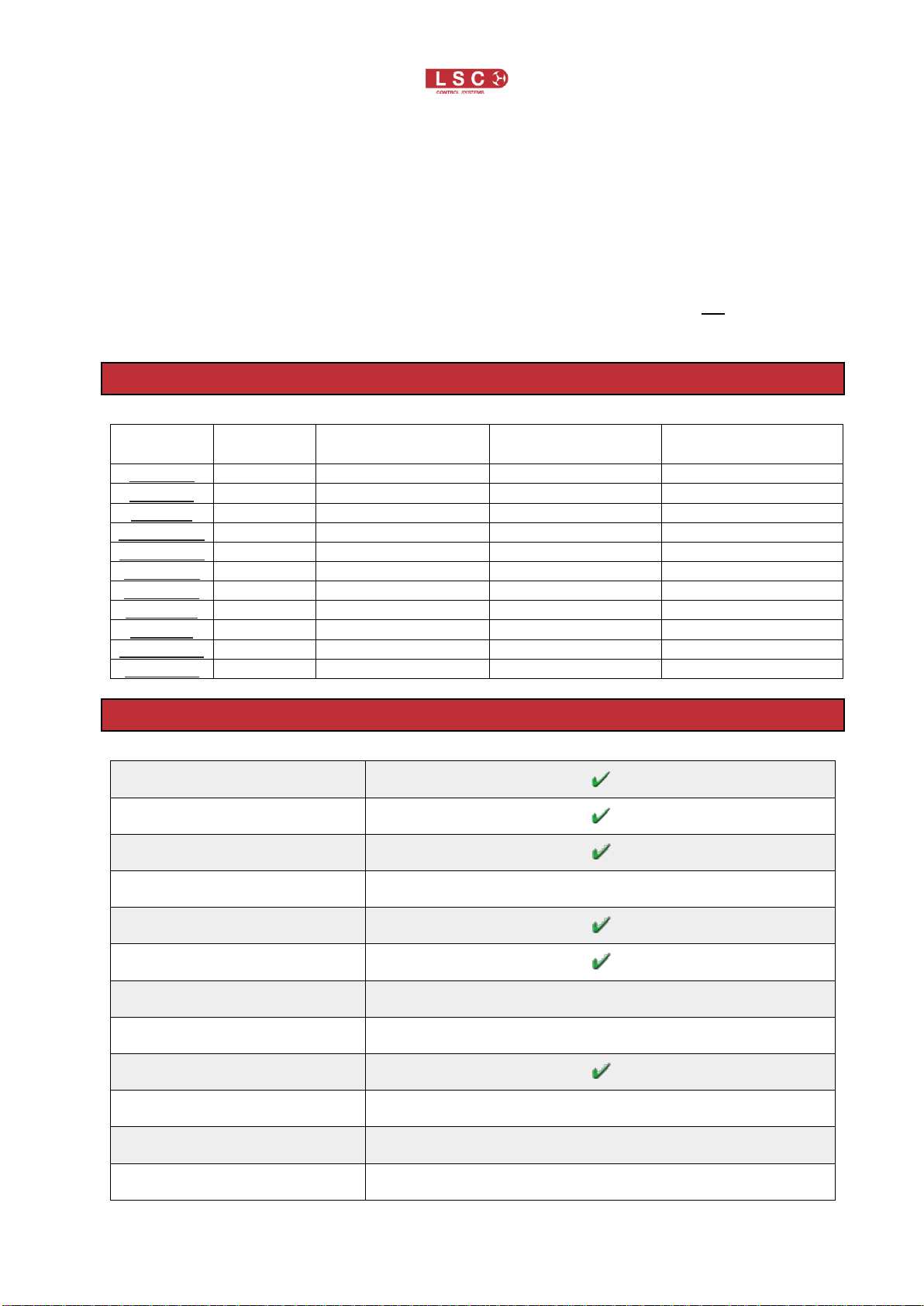
report on any RDM-enabled devices on the network. RDM can be used to:
•Change DMX start addresses
•Report faults
•Change fixture mode settings
•Request a list of fade curves available from a dimmer rack
•Report on lamp hours usage per fixture
•Report on the temperature of dimmers and other connected devices
RDM allows a lighting console to discover all the devices connected to its outputs and even how
many DMX slots each item requires. This information could then be used to auto-patch the entire
rig. The user settings of all the devices could be saved as part of the show file, so that when the
show is reloaded into the console, the system could ensure that all devices are still connected
and working, then checkthat the Pan invert settings andcustom dimmer curves on certain devices
have not changed. In the case of a faulty moving light, a new light could be connected and the
user settings (for example, DMX address, mode, tilt invert) automatically uploaded to the new
unit.
RDM is backwards compatible with existing DMX512 equipment, allowing non-RDM devices to
be connected to the same cable as RDM devices. The non-RDM units, if fully conforming to the
DMX512-A standard, will simply ignore all the RDM data. The only exception to the rule is
DMX512-A data splitters. Non-RDM units will simply block (stop) all RDM data from any devices
connected downstream of the DMX512-A splitter. Therefore, any lighting system using RDM must
use RDM-enabled DMX512-A data splitters.
4Wireless DMX512 Operation
Note: This option is no longer supported or supplied by LSC. This information is only supplied for
earlier MDR splitters that were fitted with this option.
For full wireless DMX512-A operation, please refer the manufacturer’s websites:
Wireless Solutions (W-DMX) www.wirelessdmx.com
City Theatrical (SHoW DMX) www.citytheatrical.com
The wireless DMX512 modules supplied by LSC for the MDR range of splitters are modified
receiver boards from the manufacturers listed above.
LSC do not supply wireless DMX512 transmitters. Please contact the above manufacturers for
the appropriate transmitter to work with the MDR splitter.
The wireless DMX512 module can work as a sole DMX512-A input source for the splitter or as a
backup source to the cable input, thus providing full redundancy for the DMX512-A cable input. If
both wireless DMX512 and cable DMX512 are receiving data, the cable DMX512 input has
priority. However, if there is a failure on the cable DMX512 input, the MDR splitter has an auto-
switching feature that seamlessly switches the input priority to the Wireless input. When the failure
on the cable DMX512 input has been rectified, the MDR splitter will automatically switch back to
the cable DMX512 input.
1. Connect Power, input (if required), thru (if required) and outputs as per the DMX512
section above.
2. For Wireless Solutions W-DMX models, press and release the Function button to
synchronise the receiver to the transmitter device. This process may take up to 10
seconds to synchronise. Once synchronised the Status indicator will illuminate.
3. To unlink the receiver from the transmitter, press and hold the Function button until the
Status indicator goes off. The receiver is now not linked to the transmitter.
4. For City Theatrical SHoW DMX models, there are two buttons, a display and a Status
indicator. The display shows four menu choices, various settings, and unit information.

MDR DMX-RDM Splitter
User Manual
Page 10
The display will timeout after 10 seconds if no button activity is detected. The left and
right buttons are used to move through the menus and to adjust and select settings. The
Status indicator blinks red to indicate operation and No Transmitter Detected and blinks
green to indicate operation and Transmitter Detected.
5. To set the receiver to respond to the SHoW DMX transmitter, you must select one of 64
different SHoW IDs that corresponds to what the transmitter is set to. Press the Menu
button to activate the display. The display will show the current ID: IDxx. Press the
Select button to scroll to the required ID number. The Status indicator will blink green to
indicate the receiver has synchronised to the transmitter.
6. The SHoW DMX also allows you to change the Power setting. You will not need to
change the setting as this will be set by LSC prior to the unit leaving the factory.
5Models
Model
Mount
Quantity of DMX
Outputs
Type of DMX
Connector
Type of Power
Connector
MDRR/R
Rack
5
5-pin XLR
IEC
MDRX/R
Rack
10
5-pin XLR
IEC
MDRJ/R
Rack
10
RJ45 Ethercon
IEC
MDRR/R5N
Rack
5
3-pin XLR
IEC
MDRX/R5N
Rack
10
3-pin XLR
IEC
MDRR/RP
Rack
5
5-pin XLR
powerCON
MDRX/RP
Rack
10
5-pin XLR
powerCON
MDRJ/RP
Rack
10
RJ45 Ethercon
powerCON
MDRT/R
Table/Truss
5
5-pin XLR
IEC
MDRT/R5N
Table/Truss
5
3-pin XLR
IEC
MDRT/RP
Table/Truss
5
5-pin XLR
powerCON
6Specifications
DMX512-A Compatible
RDM-Enabled
Integrated Termination Switch
Galvanic Isolation Barrier (Volts)
1500
Short-Circuit Protected
EMI-Filtered Outputs
Universal Input Power Supply (V
AC)
100-240
Auto Frequency Input Selection
(Hz)
47-63
Power Supply On LED
Dimensions MDRR(X/J)
480mm (w) x 44mm (h) x 110mm (d)
Dimensions MDRT
320mm (w) x 50mm (h) x 125mm (d)
Weight MDRR(X)
packed (volumetric) 2kgs

MDR DMX-RDM Splitter
User Manual
Page 11
Weight MDRT
packed (volumetric) 2kgs
Construction MDRR(X/J)
All variants made from corrosion-resistant steel finished in
black powder coat with rear screened polycarbonate labels
Construction MDRT
Moulded housing made from tough ABS plastic rated to
UL94-V0
with rear screened polycarbonate labels
Conforms to CE Regulations
RCM (Australian) approved
7Compliance Statements
The MDR DMX Splitter range from LSC Control Systems Pty Ltd meets all required CE
(European), RCM (Australian) and UKCA (United Kingdom) standards.
CENELEC (European Committee for Electrotechnical Standardization).
Australian RCM (Regulatory Compliance Mark).
UK Conformity Assessed.
WEEE
(Waste Electrical and Electronic Equipment).
For more information about how to recycle your LSC product, contact the dealer where you
purchased the product or contact LSC via email at info@lsccontrol.com.au
You can also take any old electrical equipment to participating civic amenity sites (often known
as ‘household waste recycling centres’) run by local councils. You can locate your closest
participating recycling centre using the following links.
•AUSTRALIA http://www.dropzone.org.au.
•NEW ZEALAND http://ewaste.org.nz/welcome/main
•NORTH AMERICA http://1800recycling.com
•UK www.recycle-more.co.uk.
- END -
The WEEE symbol indicates that the product should not be discarded
as unsorted waste but must be sent to separate collection facilities for
recovery and recycling.
Other manuals for MDR Series
1
This manual suits for next models
4
Table of contents
Other LSC Media Converter manuals
Popular Media Converter manuals by other brands

Hall Technologies
Hall Technologies SP-HD-4C user manual

ADF Web
ADF Web HD67644-A1 user manual

TRENDnet
TRENDnet TFC-110S100 Quick installation guide

Jet
Jet JAT-800A Operations & parts manual

Maximum Controls
Maximum Controls MAX WIEGAND Quick installation guide

GENERAL RADIO COMPANY
GENERAL RADIO COMPANY 1650-B instruction manual

Altera
Altera Enpirion EP5358xUI Series user guide

Atlona
Atlona OmniStream 112 installation guide

Pro-Ject Audio Systems
Pro-Ject Audio Systems DAC Box RS Instructions for use

Victron energy
Victron energy ORI303100000 manual

Luxman
Luxman DA-150 owner's manual

Becker
Becker VARIAIR Series Assembling instructions