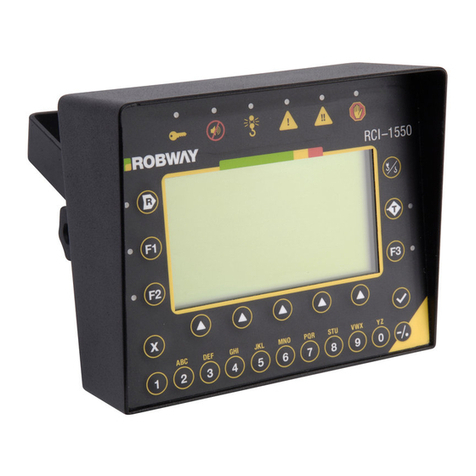
LSI-Robway RCI-1502 HRT User manual


Contents PageNo.
1. Important Safety Notice................................................................................... 3
2. General Description......................................................................................... 4
3. Operating Instructions..................................................................................... 5
3.1 Turning On the RCI-1502..................................................................... 5
3.2 Turning Off the RCI-1502 .................................................................... 5
3.3 Operating Screen................................................................................. 6
3.4 Display Functions................................................................................ 7
3.5 Data Logging and Data Downloading................................................ 9
4. Installation ........................................................................................................ 10
5. Calibration......................................................................................................... 18
5.1. Verifying Operation of Sensors........................................................ 20
5.2. Configuring User Variables .............................................................. 21
5.3. Calibrating Boom Angle.................................................................... 27
5.3.1. Calibrating Low Boom Angle............................................. 27
5.3.2. Calibrating High Boom Angle............................................ 27
5.4. Calibrating Load on the MAIN Winch............................................... 28
5.4.1. Calibrating Light Main Load............................................... 28
5.4.2. Calibrating Heavy Main Load............................................. 28
5.5. Calibrating Load on the AUX. Winch (Twin Winch)........................ 29
5.5.1. Calibrating Light Aux Load................................................ 29
5.5.2. Calibrating Heavy Aux Load .............................................. 29
5.6. Using Load/Angle Correction Function........................................... 30
5.7. Copying and Restoring Calibration Data Function ........................ 31
6. Troubleshooting............................................................................................... 37
7. Electrical Specifications.................................................................................. 44
8. Appendices....................................................................................................... 46
Page 2

1. Important Safety Notice
The RCI-1502 System is a crane device which warns the operator of impending
overload conditions and of overhoist conditions which could cause damage to
property, crane and personnel.
The system is not a substitute for good operator judgement, experience and safe
crane operation. The operator is solely responsible for the safe operation of the crane.
The operator must, prior to operation of the crane, read this manual carefully and
thoroughly and shall ensure that all operational instructions and warnings are
understood and complied with.
Proper system operation requires the operator to correctly program the RCI System to
match the crane setup and working configuration.
The system is equipped with an override key which bypasses alarms and motion cut
function at which time the system can no longer warn of impending overload and must
only be operated strictly in accordance to the crane manufacturer’s setup and
operation procedures. Operation of this key is for authorised personnel only who shall
be solely responsible for its use.
SPECIAL NOTE FOR TENSIOMETER INSTALLATION AND USE
Please Note: Remove tensiometers during dragline and piling operations.
Tensiometers (dynamometers/line-riders) are NOT designed for use on wire ropes
performing Piling operations due to the high cycle and high speeds combined with high
linepulls.
Please ensure they are removed before commencing operations.
Robway and distributors will not accept responsibility for either rope or tensiometer
damage resulting from this type of use.
Page 3

2. General Description
This Manual contains general information, installation, operation, calibration,
maintenance and parts information for the RCI-1502 Rated Capacity Indicator to suit
various Strut (Lattice) boom mobile cranes.
Refer to drawing DWG 2466 “RCI-1502 GENERAL ARRANGEMENT FOR TYPICAL
STRUT BOOM HRT SYSTEM” on Section 8.2. of the Manual for an overview of the
System.
Drawing (DWG) Numbers, where applicable in the following Sections, are also
provided for quick reference.
The RCI-1502 is a fully automatic Rated Capacity Indicator which provides a display of
the following functions:
Boom Length,
Boom Angle,
Hook Radius,
S.W.L. (Safe Working Load),
Hoist Rope Falls,
Duty (Configuration),
Actual Load of Selected Winch (Main or Aux),
Percentage of SWL (3 coloured lamps - green, amber, and red).
The RCI-1502 display also provides the following features:
Visual and audible alarms on warning (approach to overload),
overload, motion-cut, two-blocking detection, and error detection,
Self-diagnosis and error codes,
Data-logging,
Built-in calibration and fault-finding tools,
Units conversion (imperial/metric) facility,
Anti-two-block (overhoist limit) facility.
Page 4

3. Operating Instructions
The following sections explain how to operate the RCI-1502 and make best use of its
capabilities.
3.1. Turning On the RCI-1502
Power to the unit is from the crane battery (nominal 12 or 24 volts dc) through
the start-up or ignition key. In some applications an additional switch may be
used to enable the operator to switch the unit on/off as required.
As soon as power is applied to the unit, its display and other indicators should
light up and the unit should go through its self-test operation.
3.2. Turning OFF the Unit
The unit will stop working as soon as the power is removed from it by switching
off any of the switches indicated in Section 3.1 above.
Page 5

3.3. Operating Screen
The following is the operating screen of the RCI-1502 showing the general
display functions:
Multi-function
Select Button
(Length…Duty)
Multi-function
Display
(Length…Duty)
Green/Amber/Red LED
Indicator Lamps for
Percenta
g
e of SWL
LED Indicator
Lamps for
Multi-function
Select Button
(Length…Duty)
Actual Load for
Winch Selected
(Kips or Tonnes)
LED Indicator
Lamps for ATB
and Override
LED Indicator
Lamps for
Winch Select
Button
(Main or Aux)
Setup/Cancel
Button for Use
in Calibration
Mode
Winch Select
Button
(Main or Aux)
Test/Enter Button
(Pressing Test will Restart
the System; Enter is Used in
Calibration Mode)
UP/DOWN Buttons
for Changing Duty
& Falls, and for Use
in Calibration Mode
LED Indicator for
Units in Use
(OFF = Metric &
ON = Im
p
erial
)
Page 6

3.4. Display Functions
The RCI-1502 has 2 LCD display windows and 6 front panel push buttons. The
display panel can also be grouped into four parts as follows:
3.4.1. “Approach to Rated Capacity” Indication Lamps
This is the uppermost part of the display which contains three coloured
lamps to indicate “approach to rated capacity”. Factory settings are as
follows:
Green: 50 to 84%, Amber: 85 to 99%, Red: 100 to 110%
Amber lamp flashes when first trip point is reached (i.e. 85%
Rated Capacity) plus an intermittent audible alarm.
Red lamp will flash at 100% of rated capacity plus a continuous
audible alarm.
Red lamp will stop flashing and will stay ON when the lifted load
exceeds 110% of SWL plus a continuous audible alarm. Crane
motion controls are also activated at this stage if fitted.
3.4.2. Numerical LCD for Various Functions
This is a numerical LCD display, just below the indication lamps
mentioned above, which shows the LENGTH, ANGLE, RADIUS,
S.W.L., FALLS, and DUTY status.
This window is also used to display ERROR codes when any errors are
detected. The error function cannot be manually selected but will be
displayed automatically if there are any errors. Please refer to Section
6. “Troubleshooting” for the meaning and description of the error codes.
The above functions are selected by pressing the SELECT button on
the front panel. The selected function is indicated by the lamp next to
the labels. The display functions are as follows:
LENGTH
The numerical display shows the BOOM length, in unit selected (feet or
metres), for the winch selected.
ANGLE
The numerical display shows the current working angle in degrees
which is read from the main boom angle sensor.
RADIUS
The numerical display shows the current working radius, in unit selected
(feet or metres), for the winch selected.
SWL
The numerical display shows the current maximum safe working load in
unit selected (kilopounds or tonnes). The S.W.L. will depend on the
current crane configuration (duty), winch selected (if twin winch), the
maximum linepull and the falls selected.
Page 7

FALLS
The numerical display shows the number of falls (parts of line) used for
the winch selected. To change the falls, press the UP/DOWN arrow
keys to ramp to the desired falls number while the FALLS indicator is
on, make sure the correct winch is selected.
DUTY
The numerical display shows the current duty (or configuration) number
selected. Each system manual is supplied with a DUTY LISTING for a
given application. Please refer to the DUTY LISTING at the rear of the
manual for a description of the duties. A plastic encapsulated version is
also supplied with the system for the crane operator’s quick reference in
the cabin.
To change the Duty number, use the UP/DOWN key to ramp to the
desired value, while the DUTY LED indicator is on.
3.4.3. A.T.B. (Anti-Two-Block) and O/RIDE (Override) Indication LEDs
This part of the display has two red LED’s which shows the current
status of the following functions:
O/RIDE - LED ON when over-ride/bypass key is switched on.
A.T.B. - LED ON when on two-blocking condition.
The RCI-1502 is supplied with a standard Anti-Two-Block (ATB) input
for connecting an optional ATB sensor to prevent two-blocking. When
the ATB indicator on the front panel is lit, a two-blocking condition has
occurred and further hoisting is stopped by activating the motion cut
relay, if installed.
3.4.4. Numerical LCD for Current Load Readout
This part has a numerical LCD which shows the current load, in unit
selected (kilopounds or metric tonnes), on the winch selected.
There are three red LED’s on the left side of this window. The MAIN
and AUX LED’s indicate which winch is selected. The LBS LED
indicates the units selected. LED ON means Imperial Units (kips, feet)
and LED OFF means Metric Units (tonnes, metres).
Use the WINCH SELECT button to switch between MAIN and AUX
winches. For Single Winch cranes, only the MAIN winch is active and
the AUX LED is disabled.
Although the RCI-1502 will always check safe operation for both
winches, you should make sure that the correct winch is selected as the
winch selection affects the values shown on the displays.
When the ACTUAL LOAD exceeds the SWL for the current crane
configuration the RCI-1502 will activate audible and visual alarms.
Page 8

If the overload is higher than the SWL % for MOTION CUT OUTPUT,
set in calibration mode, the instrument will also activate the motion cut
relay, if installed. This will then stop further over-loading of the crane.
To bypass or temporarily disable motion cut, the operator must use the
over-ride key which should be held by the site-supervisor. When the key
is inserted into the display and is turned on the O/RIDE indicator is
illuminated as a reminder.
ROBWAY recommends that the over-ride key be switched OFF at
all times and the over-ride key be held by the site-supervisor.
3.5 Data Logging and Data Downloading
For downloading data to PC, connect the Data-Logging Download Cable (Part
No. CABCOM 1261) between the RS-232 socket at the back of the RCI-1502
display and the PC.
Please refer to Section 8.1. “DATA LOGGING ON RCI SYSTEMS” at the rear
of the manual for usage information and details.
Page 9

4. Installation
SETTING UP THE CRANE
Lower the crane boom to a safe and convenient position.
INSTALLING BOOM PARTS
Boom Angle Sensor
Fix the angle sensor orientated for right hand side (RHS) of the boom in a
convenient position close to the operator's cab by bolting/welding the mounting
bracket provided in a vertical plane at 90 degrees to the boom centreline.
It is usual to fit the angle sensor to the 'inside' of the LHS boom butt
section. This position usually provides good mechanical protection.
Ensure the arrow on the enclosure is pointing to the boom tip.
Mount/bolt the sensor on the mounting bracket and route the cable carefully
around the boom pivot to the cab. Clip the cable to the boom and turret using
adequate straps/cable ties provided ensuring that cable is not pinched or
stretched as boom moves through its full luffing arc (see also “Cabling – Boom
Sensors” item in this Section). Only connect the plug when finished welding.
Drawing Reference:
DWG 1099 – “Electronic Angle Sensor, Dimensional Drawing”
Please note that high tensile booms require proper welding procedure
specifications. Obtain specialist assistance in these cases.
Electronic angle sensor and typical installation at the boom butt section
Load Sensor
The RCI-1502 System uses tension-based load sensing method which directly
senses the line-pull generated when lifting the load. Sensors can be
dynamometers/tensiometers (also known as line-riders) or tension plate type
cells fitted into the dead-end of the hoist reeving. Load-pin type load-cells may
also be used.
Page 10

Dynamometer/Tensiometer Type
Please Note:
Remove tensiometers during dragline and piling operations. Refer to
Section 1. “Important Safety Notice” – Special Note for Tensiometer
Installation & Use.
This is a three-pulley arrangement load sensor with a beam type
loadcell (model RW5000) mounted within. The tensiometer monitors the
hoist rope line-pull as the hoist rope passes through the three sheaves.
The tensiometer sheaves must be suited to the diameter of the hoist
rope. The dynamometer type units are usually rigid mounted on a
suitable location on the boom tip section or fitted with articulating arm
assembly at the boom butt section. The arcticulating arm assembly
allows the unit to follow the natural position of the hoist rope relative to
the boom itself.
Mounting the dynamometer using an articulating arm on lattice boom
cranes requires two cross braces to be fitted to the boom top chords.
One to be utilised as a 'take-off' point for the articulating arm and the
other to secure timber to create a 'landing zone' for the tensiometer so
as to not damage the boom chords or lacing during fast hoist rope
working.
For cranes without fly-jibs, the dynamometers/tensiometers are usually
rigidly mounted on the boom tip section. Fabricated brackets may be
required to attach the tensiometer to the boom top and align it to the
hoist rope.
For cranes with fly jibs, the fly-jib mast aux winch idler sheave
necessitates using an articulating arm mounting to allow the
tensiometer to follow the aux rope natural line over the mast idler
sheave. Alternatively, the tensiometer may be mounted on the fly-jib tip
section, or, off the boom butt section using an articulating arm if the aux
and main winches are side by side.
The beam type loadcell inside the dynamometer outputs an electrical
signal proportional to the hoist rope line-pull forces which the RCI-1502
unit then converts into hook-load weight. Correctly following the
calibration procedures is essential for accurately determining the hook
load weight.
Drawing References:
DWG 1393 – “Overall Dimensions, HRT-3MM Micro-Mini
Dynamometer”
DWG 0875 – “General Arrangement, HRT-3MM Dynamometer”
DWG 0422 (Sheets 1-2 of 2) – “General Arrangement, HRT-3 Dyno”
DWG 0104, 0786, 0787 – “Parts List for HRT-3 Dynamometer”
DWG 1795 – “Dimensional Detail, HRT-4 Dynamometer”
DWG 0796 – “General Arrangement, HRT-4 Dynamometer”
DWG 0799, 0340 – “Parts List for HRT-4 Dynamometer”
DWG 0370 – “General Arrangement, Standard Artic. Arm for Dyno”
DWG 0805 – “General Arrangement, Heavy Duty Artic. Arm for
Dyno”
DWG 2468 (Sheets 1-4 of 4) – “Typical Installation of Dyno on Strut
Boom Cranes”
Page 11

Typical installation of dynamometers/tensiometers on strut boom cranes
Tension Cell Type
A tension plate-type load cell may be fitted at the hoist rope dead-end of
the boom tip section to sense the hoist line-pull. Robway tension cells
are supplied with standard “side plates” (or “sister plates”) to provide
extra protection against extreme twisting during crane operation.
Special fittings such as an “adapter plate assembly” may be required to
fix the tension cell between the boom lug (pad eye) and hoist rope
wedge socket. This adapter plate assembly must be specially-fabricated
and supplied by the customer to suit the dimensions of the lug and
socket at the dead-end termination point. It should be fabricated from
high-tensile grade material such as “Bisalloy 80 Steel” for plates and
“grade 4140” for pins, and should also provide for the existing wedge
socket and pin to be re-used. Robway also recommends that the
adapter plate assembly be proof-load tested by a certification body prior
to installing it on the crane.
Alternatively, Robway can supply the adapter plate assembly (proof-
load tested and certified) at extra cost at the time of ordering the RCI-
1502 system. Dimensional details of the lug, wedge socket and pin will
also be required by Robway at the time of ordering.
Drawing References:
DWG 0990 – “Tension Plate Cell Dimensions”
Page 12

Tension cell with Robway-manufactured adapter plate assembly and typical installation on
hoist rope deadend
Load Pin Type
The load pin is fitted to and is utilised for the axle shaft of a Single-
Sheave Dynamometer. This type of dynamometer can either be
supplied by Robway, or fabricated/supplied by the customer. For
customer-supplied dynamometer, Robway will only supply the load pin
to suit.
The Single-Sheave Dynamometer with integral Load Pin is usually rigid-
mounted on a suitable location at the boom tip section.
Drawing References:
DWG 1938 – “Dimensional Detail, RW1500 Load Pin”
DWG 0991 – “General Details, Single Sheave Dynamometer”
Typical installation of load pins in single sheave dynamometers
Page 13

Anti-Two-Block (Optional Item)
Fix the anti-two-block (ATB) switch mounting bolt by welding it to the boom
head preferably so that the bob weight (when suspended from the switch) can
be fitted to the static hoist rope below the rope anchor. Check that the switch
works correctly as the boom luffs throughout its working range.
Additional switches (for fly-jibs) can be added. Connection is via the bullet-type
connectors from the cable. When more than one ATB switch is required (e.g.
main & fly), connect the ATB cables of the switches in series via the bullet-type
connectors.
Hang the bob weight assembly from the switch eye after cutting the chain to
length if desired to suit winch line speed. Repeat the procedure if required for
rooster or fly jib.
Drawing References:
DWG 2934 – “Dimensional Detail, BB5 Anti-Two-Block Switch”
DWG 0667 (Sheet 3 of 3) – “ATB Switch Installation Details, Strut Boom”
Please note that high tensile booms require proper welding procedure
specifications. Obtain specialist assistance in these cases.
Model BB-5 anti-two-block (ATB) switch
Cabling (Boom Sensors)
Load, angle, and ATB cables should be fixed firmly to where they are installed
and routed along the boom chords through to the crane cabin ensuring freedom
of movement around the boom pivot pin.
The cables are normally quite robust. They should be treated with care,
however, as even a small amount of damage can be very costly due to down-
time or intermittent behaviour. Always support the cable in such a way that
there is no "excessive" strain applied, such as tension or flexing. The cable
should be strapped to a fixed member that it runs along, unless it is held within
a cable tray or trunking. Clip cables at approximately 600mm intervals or where
suitable to secure them firmly to the boom. Avoid sharp bends such as around
a sharp corner. Where there is to be flexing, the installer must ensure that the
bending is reduced to an absolute minimum to avoid fatigue breakage of the
conductors.
Drawing Reference:
DWG 1244 – “RCI Series Cable Connections”
Page 14

Connectors
It is recommended that the installer applies a suitable silicone grease (e.g.,
Dow Corning 4 “Electrical Insulating Compound” or any similar compound) on
the plugs and sockets prior to connecting the cables. The silicone grease
should be smeared across the connector contact points to increase the water
proofing of the connector.
INSTALLING CABIN PARTS
Display Unit and Key Switch Box
Fit the RCI-1502 Display Unit and Key Switch Box in a convenient position in
the crane cabin such that the operator can view the displays and reach the
push buttons comfortably.
Connect the Switch Box power supply lead to the key start switch or directly to
the battery via a relay that is energised by the key start switch. Ensure that the
polarity of the power supply is correctly connected.
Standard back plate bracket and kit comprising of bolts and nuts are provided.
Special bracket may need to be fabricated on site for suitable mounting in the
cabin.
Connect the load, angle, and anti-two-block ATB cables to the display unit.
Note: If a good earth connection between the mounting bracket and the
cabin cannot be guaranteed then the earthing wire attached to the base of
the display must be used to properly earth the display. Failure to do so
could result in a non-operational ATB signal and faults due to Radio
Frequency Interference.
Drawing References:
DWG 0279 – “Dimensional Drawing, RCI-1502 Display”
DWG 2459 – “Dimensional Detail, RCI-1502 Switchbox”
DWG 3336 – “RCI-1502 Switchbox V2 Wiring Diagram”
Display unit and typical installation inside the cabin
Page 15

WIRING SLEW SWITCH/ES AND MOTION CUT OUTPUT
Slew/Proximity Switch/es (Optional Items)
The slew switch is used when the crane has different zones of SWL (e.g. over-
rear ratings, over-side ratings, etc.). The switch will convey a signal to the
display when the crane moves into a zone of different capacity rating. The RCI-
1502 system can interface with up to three switches maximum.
The switch is magnetically switched and requires a metal target to switch ON.
Fabricate, fix and secure a suitable mounting plate to the switch between the
two locknuts supplied. Mount the plate/switch assembly at a suitable location
on the revolving upperstructure preferably so that the switch moves and rotates
with the upperstructure. The metal target plate must be mounted at a safe and
suitable location on the carrier about which the upperstructure rotates.
Alternatively, fix the switch and target plate around the centre post of the crane
slew (refer to typical installation photo below).
The gap between the switch and target must not exceed 10mm. The switch
distance can be adjusted via the locknuts.
Connect the switch to the RCI-1502 Switchbox as per DWG 3336 (refer to
Section 8.2. “Drawings” for details).
Drawing References:
DWG 2461 – “Dimensional Details, Proximity Switch (SWIPROX02)”
DWG 2462 – “Dimensional Details, Proximity Switch (SWIPROX03)”
DWG 930050 – “RCI Slew Switch Mounting”
Typical installation of slew/proximity switch
Motion Cut Output
The standard RCI-1502 Switchbox has an in-built relay to output the motion-cut
signal. This allows connection of the crane’s lockout solenoids direct into the
Switchbox.
The Switchbox is fitted with a standard 24VDC (contact rating of 10A) relay
when supplied from the factory. A spare 12VDC (contact rating of 10A) relay is
also supplied with the installation kit supplied with the system. This is to replace
the 24VDC relay if the crane’s nominal supply is 12VDC.
To wire the crane’s lockout solenoids, open the RCI-1502 Switchbox and use
the following relay connections to match the solenoids:
Page 16

Relay Terminal No. Contact Output Description
3 Normally Open
4 Common
5 Normally Closed
The lockout solenoids on cranes are normally energised when crane is in safe
condition (no alarm) and are de-energised when a motion cut condition occurs.
Use contact terminals 4 (com) and 5 (NC) of the motion cut relay to wire the
supply coil of the lockout solenoids. During motion cut activation, the motion cut
relay is de-energised. This opens the relay contacts and also de-energises the
lockout solenoids.
The Switchbox has a spare gland for motion cut cable entry. Please note that
the motion cut cable is not supplied with the RCI-1502 System as a standard
component.
Drawing Reference:
DWG 3336 – “RCI-1502 Switchbox V2 Wiring Diagram”
Page 17

5. Calibration
WARNING
Calibration by untrained personnel may result in corruption of sensitive
calibration data. Therefore, entry into calibration routines should only be
performed by trained personnel.
Entering Calibration Mode and Selecting Calibration Functions:
Make sure that the correct duty number (crane configuration) and falls
(parts of line) are selected,
Insert the over-ride key switch into the RCI-1502 Switchbox and turn it on,
make sure that the O/RIDE indicator on the front panel is lit,
Press and hold the SETUP button for about 2 seconds,
The TOP window should show F-xx, where xx is the last calibration function
performed or 00 if this is the first time you entered calibration mode,
Once calibration mode is entered use the UP/DOWN keys to ramp through
the calibration functions,
When the correct function code is shown in the TOP window press the
ENTER button to select that function,
To exit calibration mode either select F-00 or press the CANCEL key until
the F-xx code is cleared from the TOP window.
Tools/Items Required for Calibration:
An accurate angle finder for calibrating boom angle sensor,
An accurate tape meter of at least 100 ft. long (30.5m) for verifying radius,
Known test weight of at least 75% of the hoist rope single linepull for
calibrating the heavy load,
Note: For twin winch cranes, two test weights may be required, one for
each winch if different linepulls.
Software configuration sheets and function codes list provided at the back
of this manual.
Page 18

Map of Calibration (Suggested Order):
1. Set date and time (F-32 to F-34).
2. Verify that raw counts stay within 33-999 for full working range of all sensors
(F-07, F-15, F-19). F-19 is only required for twin winch cranes.
3. Review all crane geometry against the supplied Crane Configuration settings
for correctness (F-45 to F-53) – refer also to Section 8.4. “RCI System Crane
Configuration Sheet / Duty Listing” at the rear of the manual for factory default
settings.
4. Review all SWL % parameters against actual requirements (F-42 to F-44) and
change if required – refer also to Section 8.4. “RCI System Crane Configuration
Sheet / Duty Listing” at the rear of the manual for factory default settings.
5. Review the data logger recording points against actual requirements (F-61 to
F-67) and change if required – refer also to Section 8.4. “RCI System Crane
Configuration Sheet / Duty Listing” at the rear of the manual.
6. Check Metric/Imperial units switching and set to required unit of measure. Use
function code (F-72) if single winch crane, or code (F-75) if twin winch crane.
7. Calibrate low & high boom angle sensor (F-09, F-10).
8. View and check accuracy of the calibrated angle value in degrees on function
code (F-08).
9. Calibrate light and heavy main winch load (F-02, F-03).
10. View and check accuracy of the calibrated Main load value in tonnes or kips,
whichever “unit” is selected on item #6 above, using function code (F-01).
11. Calibrate light and heavy aux. winch load (F-05, F-06) – if twin winch crane.
12. View and check accuracy of the calibrated Aux. load value in tonnes or kips,
whichever “unit” is selected on item #6 above, using function code (F-04) – if
twin winch crane.
13. Apply averaging of samples, if required, using function code (F-27). Default
value is 0 and maximum setting is 25. Try different value settings to stabilise
the load readout if necessary. Refer to Section 5.2.18. for details.
14. Apply load/angle correction factor, if required, using function codes (F-68 to
F-70) if single winch crane, or (F-68 to F-71) if twin winch crane. Refer to
Section 5.6. “Using Load/Angle Correction Function” for details and
procedures.
15. Set the rigging SWL, if required, using function using code (F-71) if single
winch crane, or (F-72 to F-73) if twin winch crane. Refer to Section 5.2.33.
“Main Winch Rigging SWL” and 7.2.34. “Aux Winch Rigging SWL” for details.
16. Once satisfied with the calibration results, manually record (pen & paper) the
calibration data using function code (F-40) and all settings mentioned above.
Refer to Section 5.7. “Copying & Restoring Calibration Data Function” for
details and procedures.
Page 19
Other manuals for RCI-1502 HRT
1
Table of contents
Other LSI-Robway Lifting System manuals
Popular Lifting System manuals by other brands

barbaric
barbaric uniWood UWL 3 installation manual

LGMG
LGMG SR1623 Operation and maintenance manual

John Bean
John Bean EELR537A Installation, operation & maintenance manual

morse
morse 400A-72SS-114 Operator's manual

JLG
JLG EcoLift50 Service and maintenance manual

Atlas
Atlas PV-15PX Installation & operation manual