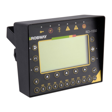
LSI-Robway RCI-1550 LM User manual


CONTENTS
1. ......................................................................................................................5IMPORTANT SAFETY NOTICE
2. ................................................................................................................................................5SPECIAL NOTES
2.1. ............................................................................................5BRANDNAMES,TRADENAMES AND TRADE MARKS.
2.2. ...............................................................................................................................5IMPORTANT SAFETY NOTICE
2.3. ...........................................................................................................................6LIMITED PRODUCT WARRANTY
2.4. ........................................................................................................................6GLOSSARY OF SOME USED TERMS
3. ................................................................................................................................................6INTRODUCTION
3.1. ............................................................................................................................................6MANUAL CONTENTS
3.2. ..............................................................................................................................................6SCOPE OF MANUAL
3.3. ..........................................................................................................................................6INTENDED AUDIENCE
3.4. ..............................................................................................................................6PERSONNEL QUALIFICATIONS
4. ...................................................................................................................................7SYSTEM DESCRIPTION
4.1. ............................................................................................................................7MULTI-PURPOSE APPLICATION
4.2. ..............................................................................................................................................................7PURPOSE
4.3. ......................................................................................................................................................7CAPABILITIES
4.4. ...........................................................................................................................................8AVAILABLE OPTIONS
5. ...........................................................................................................................9INSTALLATION - GENERAL
5.1. ......................................................................................................................................9SETTING UP THE CRANE
5.2. ..................................................................................................................................................9ANGLE SENSORS
5.2.1. ........................................................................................................9Changing from RHS to LHS mounting
5.3. ................................................................................................................................................9LENGTH SENSORS
5.3.1. .......................................................................................................................................................9General
5.3.2. ....................................................................................................10110’ Length Sensor – (DRURW33LAA)
5.3.3. .....................................................................................................11140’ Length Sensor– (DRURW43LAA)
5.3.4. ...........................................................................................................................................12Pay-out Cable
5.4. ....................................................................................................................12ANTI-TWO-BLOCK (IF INSTALLED)
5.4.1. ................................................................................................12Rectangular type Anti-two Block switches
5.4.2. .......................................................................................................12Tubular type Anti-two Block switches
5.4.3. ..............................................................................................................12Multiple Anti-two Block switches
5.4.4. ..........................................................................................................12Bob-weight (both types of switches)
5.5. .......................................................................................................................12LOAD MOMENT BASED SYSTEMS
5.5.1. ...................................................................................................................................................12Overview
5.5.2. .................................................................................................12Pressure Transducers (Luffing Cylinder)
5.6. ......................................................................................................................................13CABLING AND GLANDS
5.7. ...................................................................................................................................................14DISPLAY UNIT
5.8. ..................................................................................................................................................15CONTROL UNIT
5.8.1. ....................................................................................................................................15Power Supply (PS)
5.8.2. ..............................................................................................................................................16CPU Section
5.8.3. .................................................................................................................................17Analog Input Section
5.8.4. .....................................................................................................................................17Digital IO Section
5.9. .............................................................19UPGRADING TO RCI-1550 FROM EARLIER ROBWAY MODEL DISPLAYS.
6. .......................................................................................................................20OPERATING INSTRUCTIONS
6.1. ............................................................................................................................................20THE LCD DISPLAY
6.1.1. ..........................................................................................................................................21The Bar Graph
6.1.2. ...........................................................................................................................................................21SWL
6.1.3. .......................................................................................................................................................21Length
6.1.4. .........................................................................................................................................................21Angle
6.1.5. .......................................................................................................................................................21Radius
6.1.6. ..........................................................................................................................................................21Load
6.1.7. ..............................................................................................................................................22Error Codes
6.2. ......................................................................................................................................22THE DISPLAY KEYPAD
6.2.1. ........................................................................................................................22Function Key (F1, F2, F3)
6.2.2. .........................................................................................................................................22Soft Menu Keys

6.2.3. ..............................................................................................................................22Alpha-Numerical Keys
6.2.4. .................................................................................................................................................23Ok (
) key
6.2.5. ..........................................................................................................................................23Cancel (x) Key
6.2.6. ....................................................................................................................................................23Tare Key
6.2.7. ..............................................................................................................................................23Rigging Key
6.3. ..............................................................................................................................................24LED INDICATORS
6.3.1. ...........................................................................................................................................24Override LED
6.3.2. ...................................................................................................................24Audible Alarm Disabled LED
6.3.3. ........................................................................................24A.T.B. Indicator (anti-two-block or over-hoist)
6.3.4. ............................................................................................................24Approach to Rated Capacity LED
6.3.5. .................................................................................................................24100% Capacity Exceeded LED
6.3.6. ........................................................................................................................................24Motion Cut LED
6.4. ................................................................................................................25OVER-RIDE KEY-SWITCH (IF FITTED)
6.5. ....................................................................................................................25DISABLE KEY SWITCH (IF FITTED)
6.6. ..............................................................................................................................25TURNING ON THE RCI-1550
6.6.1. ............................................................................................................................................25On Power Up
6.7. ...........................................................................................................................................26MENU NAVIGATION
6.7.1. ................................................................................................................................26Config Change Menu
6.7.2. .........................................................................................................................................26Function Codes
6.7.3. ..............................................................................................................................27Display Options Menu
6.8. ....................................................................................................27DATA LOGGING AND DATA DOWN-LOADING
7. ..................................................................................................................................................28CALIBRATION
7.1. .....................................................................................................................................28CALIBRATION PURPOSE
7.1.1. .............................................................28Entering Calibration Mode and Selecting calibration functions.
7.1.2. ........................................................................................................................28Function codes menu item
7.1.3. ..............................................................................................29General information regarding text editing
7.2. ...........................................................................................................29CALIBRATION FUNCTIONS BREAKDOWN
7.2.1. ................................................................................................................................29Exit Calibration Item
7.2.2. ..............................................................................................29View Main Load and View Aux Load items
7.2.3. ..............................................................................................................................30View Boom Angle item
7.2.4. ..................................................................................................................................30View Jib Angle item
7.2.5. ......................................................................................................................................30View Length item
7.2.6. ...............................................................................................................................31Set Gain Trans 1 item
7.2.7. ...............................................................................................................................31Set Gain Trans 2 item
7.2.8. ................................................................................................................................32Set MUX. Delay item
7.2.9. ..................................................................................................................................32No. of Samples item
7.2.10. .................................................................................................................32Set Lift Value (Threshold) item
7.2.11. ..............................................................................................................33Set Rigging Load Threshold item
7.2.12. .......................................................................................................33Correct Radius (Unladen boom) item
7.2.13. ............................................................................................................33Correct Radius (laden boom) item
7.2.14. ...........................................................................................................34Set Rigging Length Threshold item
7.2.15. .................................................................................................................................34View Directions item
7.2.16. ...............................................................................................................................34View Load-Chart item
7.2.17. ................................................................................................................................35View Digital I/P item
7.2.18. .............................................................................................................................................35Set Date item
7.2.19. .............................................................................................................................................35Set Time item
7.2.20. .............................................................................................................................36Download Logger item
7.2.21. ..................................................................................................................................36View Cal-Data item
7.2.22. .....................................................................................................................................37Change Duty item
7.2.23. .....................................................................................................................................37Change Falls item
7.2.24. ............................................................................................................37Transmit Load Moment Data item
7.2.25. ...............................................................................................................37RS-232 Communication Settings
7.2.26. ...............................................................................................................................37Receive Lm Data item
7.2.27. ............................................................................................................................37Back Up Cal-Table item
7.2.28. .............................................................................................................................38Restore Cal-Table item
7.2.29. ...............................................................................................................................38Erase Cal-Table! item
7.2.30. ..........................................................................................................................................38User Variables
7.2.31. ..........................................................................................................................................39Viewing Errors
7.2.32. .................................................................................................................39Verifying Operation of Sensors
7.3. ................................................................................................................40TOOLS REQUIRED FOR CALIBRATION

7.4. .....................................................................................................40MAP OF CALIBRATION (SUGGESTED ORDER)
7.5. .............................................................................................................................41CALIBRATING BOOM ANGLE
7.5.1. ..................................................................................................................41Calibrating a low boom angle
7.5.2. .................................................................................................................41Calibrating a high boom angle
7.6. ..........................................................................................41CALIBRATING JIB ANGLE (LUFFING FLY JIBS ONLY)
7.6.1. .........................................................................................................................41Calibrating low Jib angle
7.6.2. ........................................................................................................................41Calibrating high Jib angle
7.7. ...........................................................................................................................42CALIBRATING BOOM LENGTH
7.8. ...............................................................................................42CALIBRATING LOAD MOMENT BASED SYSTEMS
7.8.1. .......................................................................................................................................42Calibrating Load
7.8.2. ...............................................................................42Calibrating Load Overview - (Without Test-weights)
7.8.3. ...........................................................................................42Testing & calibrating Transducers Overview
7.8.4. .................................................................................................44Calibrating the Low end of Transducer 1
7.8.5. ................................................................................................44Calibrating the High end of Transducer 1
7.8.6. .................................................................................................45Calibrating the Low end of Transducer 2
7.8.7. ................................................................................................45Calibrating the High end of Transducer 2
7.9. .....................................................................................................46PREPARATION BEFORE CALIBRATING LOAD
7.10. ..................................................................................................46CALIBRATING ACTIVE (SELECTED)WINCH
7.11. .....................................................................................47BOOM STOP FRICTION (COMPRESSION)CORRECTION
7.11.1. ..............................................................................................................................................47Introduction
7.11.2. ...............................................................................................................47Boom Backstop Function Codes
7.11.3. ......................................................................................................................................47How to Calibrate
8. ................................................................................................................................................48MAINTENANCE
8.1. .......................................................................................................................................................48CHECK LIST
8.2. .................................................................................................................................................48IN-CABIN ITEMS
8.2.1. .......................................................................................................................................48Additional detail
8.3. ..........................................................................................................................49ELECTRICAL EQUIPMENT
8.4. ...........................................................................................................49RECOIL DRUM (TELESCOPIC CRANES)
8.4.1. ....................................................................................................49110’ Recoil Drum – (DRURW33LAAX)
8.4.2. ....................................................................................................50140’ Recoil Drum – (DRURW43LAAX)
8.5. ........................................................................................................51INSPECTION AFTER MAINTENANCE
8.6. ........................................................................................................................................................51RECORDS
9. ..................................................................................................................................52TROULBELSHOOTING
9.1. .............................................................................................................................................53ERROR CODE LIST
9.1.1. ..........................................................................................................53Example Errors & Possible Causes
9.1.2. ...........................................................................................54Problems That Do Not Produce Error Codes
10. .................................................................................................................55ELECTRICAL SPECIFICATIONS
11. ...............................................................................55ELECTRONIC ANGLE SENSOR SPECIFICATIONS:
12. .....................................................................................................................................................56APPENDICES
12.1..................................................................................................56DRAWINGS PART A-SYSTEM COMPONENTS
12.2. ..........................................................................................56DRAWINGS PART B-GENERAL ARRANGEMENTS
12.3. ................................................................................................................................56SOFTWARE DOCUMENTS

1. Important Safety Notice
The electronic load-charts in this system have been provided to
assist the operator to drive the crane safely and productively. These
load-charts have been provided to Robway by either the crane
manufacturer or crane owner (or their representatives).
Robway dutifully re-represent these load-charts into memory.
Motion Limiters may have been fitted to stop those functions that will
increase radius and hoist-up if the load-chart is exceeded. This
feature is provided as an aid to safer crane operation.
In certain situations, such as crane setup, the crane operator may
need to ‘over-ride’ the motion limiters. At these times, the system
can no-longer warn of overload and the crane must only be used in
strict accordance to the crane manufacturer’s setup and operation
procedures.
Proper system operation requires the operator to correctly program
the Robway system to match crane setup and working configuration.
This Rated Capacity Indicator is fitted to assist the crane operator.
This Rated Capacity Indicator is not a substitute for operator
judgement, experience or safe crane operation. At all times the
driver is ultimately responsible for safe crane operation.
2. SPECIAL NOTES
2.1. Brandnames, Tradenames and Trade Marks.
All product, brand or trade names used in this publication are the trademarks of their respective
owners and they are only mentioned to provide more accurate information for the reader.
2.2. Important Safety Notice
Notes, cautions and warnings are presented to aid in understanding and operating the equipment or to
protect personnel and equipment. At all times, relevant codes applicable to location of service must be
adhered to.
Safe, reliable operation of Robway systems require the systems to be maintained in a proper manner
and serviced by technically trained personnel using trade (or profession) recognised service
procedures and correct tools for the purpose.
Provided warnings are not exclusive, as Robway could not possibly know, evaluate and advise service
people of all conceivable ways in which service might be performed or all possible associated
hazardous consequences.
Accordingly, anyone who uses service procedures or tools which are not recommended by Robway
must first satisfy themselves to their suitability and that neither personnel safety or equipment safety
will be jeopardised by the selected method.

2.3. Limited Product Warranty
Robway Safety Systems P/L (RSS) warrants to the Buyer (Purchaser) of new products manufactured
or supplied by RSS that such products were, at the time of delivery to the purchaser, compliant to RSS
Quality Assurance documentation ISO 9001.
Any RSS product that has been repaired or altered in such a way, in RSS's judgement, as to affect the
product adversely, including installation methods and procedures, negligence, accident or improper
storage or use will be judged solely by RSS in regard to any partial or full warranty claim.
RSS's obligation under this warranty is limited to repairing or, at RSS's option, replacement of faulty
parts. Any associated transportation or labour costs (other than those directly acceptable by RSS and
consumed at RSS premises) shall not be part of the warranty claim and shall be at the originator's
expense.
Associated re-installation costs shall be at the originator's expense.
Replaced (or repaired items) by RSS are warranted for the remainder of the warranty period of the
originally supplied goods as if they were supplied with the original goods.
This above warranty period extends for 12 months from the original supply date to original purchaser
from RSS.
2.4. Glossary of some used terms
Used in Manual Alternative Description
RSS Robway Robway Safety Systems P/L.
Length Sensor Boom Length Measures telescoping boom sections
Pressure Transducer Measures hydraulic pressure
Boom Angle sensor BAS Measures angle to horizon
ATB Over-hoist Over-hoisting the hook into the boom tip.
RCI LMI same, being Rated Capacity Indicator or
Load Moment Indicator.
3. INTRODUCTION
3.1. Manual Contents
This manual contains installation, operation, calibration, maintenance and parts information for the
RCI-1550 Crane Rated Capacity Indicator system manufactured by Robway Safety Systems suitable
for installation to fixed or mobile telescopic cranes.
3.2. Scope of Manual
Refer to Contents section. This section is an itemised list of sections with their corresponding section
number and page number.
3.3. Intended Audience
This manual is intended for use by field engineering, maintenance, operation and repair personnel
trained by RSS or familiar with RSS methods and application knowledge.
3.4. Personnel Qualifications
The procedures described in this manual should be performed only by persons who have read the
safety notices in this manual, have read, and understood the relevant section and who are suitably
qualified and trained to perform the procedures within.

4. SYSTEM DESCRIPTION
4.1. Multi-purpose Application
The RCI-1550 is designed to suit Telescopic Boom Cranes of
either mobile or fixed installation.
This manual covers the use of Load Mom ent based sensors an d
calibration refer to cranes w here the te nsion cell/s are fitte d to
monitor the forw ard moment fo rces of the boom and then calcu late
the hook load.
4.2. Purpose
The RCI-1550 automatic Rated Capacity Indicator (RCI) is designed to assist the operator in the
course of normal crane operation and consists of boom angle, length, slew and ATB sensors.
Additionally, the system has tension cell/s to monitor the boom pendant forces to more effectively warn
the crane operator of;
impending overload.
actual overload
and is designed to activate function motion-cut (if fitted/connected)
4.3. Capabilities
The RCI-1550 display provides the following capabilities:
Suitable for mobile, crawler and fixed type telescopic-boom cranes, load-moment sensor based,
Multi-hoisting winch operation,
Provides monitoring and display of;
Boom Length,
Boom Angle & Luffing fly jib Angle (as applicable)
Boom Tip Radius,
Boom Tip Height,
Lifted Load,
Selected Hook Falls,
Selected Crane configuration,
Crane configured S.W.L,
S.W.L. as a percentage of Crane configured SWL, and
Restricted Slew zones,
Hoist/Luff direction (if required for friction compensation).
Provides visual and audible warnings, motion-cut and Anti-Two blocking detection,
Self-diagnosis and error codes,
Unique simulated analogue display for visual feedback of S.W.L. percentage,
Multi-line text character window to display messages,
Built-in calibration and fault-finding tools.

4.4. Available Options
Options for
slew-zone continuous monitoring encoder sensor
hook height
multiple switch/analogue input/output expansion
engine management
special alarms
on-site configurable user data,
data-logging ( customer formats optional ),
printing,
ROBWAY also cater for custom applications and special user
requirements. Please contact your nearest ROBWAY distributor or
ROBWAY directly.

5. INSTALLATION - GENERAL
5.1. Setting Up the Crane
Lower the crane boom to a safe and convenient position for installation of system components.
High tensile booms require proper welding
procedure specifi cations. Obtain special ist
assistance in these cases.
Please r efer to the General Arrangement
drawings at the rear of the manual for an
overview of the configuration.
5.2. Angle Sensors
The telescopic crane Boom Angle Sensor is mounted on the electrical sub-plate within the recoil drum.
Factory supply (unless ordered specifically) is for RH mounting. If mounting to LHS the BAS must be
realigned. Refer next paragraph.
5.2.1. Changing from RHS to LHS mounting
The Boom Angle Sensor (BAS) is physically mounted within the recoil set for RHS boom mounting as
standard. Should the recoil drum be mounted to the LHS of the boom, the BAS will need to be rotated to the
LHS mount position.
Undo the 2 mount screws and rotate the BAS clockwise to the alternative mount position.
Refix the 2 mount screws.
5.3. Length Sensors
5.3.1. General
Fix the recoil drum and pay-out cable to the RHS side of the main boom (LH installations require
the electronic angle sensor to be re-positioned on its mount, (refer to the above BAS section) by
welding the mounting bracket provided.
Route the cable carefully from the recoil drum back around the boom pivot to the cab. Fix the cable
to the boom and turret using adequate fixings ensuring that the cable is not pinched or stretched as
the boom moves through its full luffing arc. Only connect the cable to the Control Unit when
finished welding.

5.3.2. 110’ Length Sensor – (DRURW33LAA)
INSTALLATION- (Please read through before starting)
Ensure that the face onto which the unit is to be mounted is flat, vertical and parallel to the
line of cable pay-out. The mounting position should allow free uninterrupted pay-out of
cable.
The unit should be mounted with fixing brackets in the horizontal plane and be parallel with
the crane boom. An anti-condensation filter unit is fitted to the unit close to cable entry
glands, this should be at the lowest point when the reel is mounted.
Weldable pads are usually supplied with the units to provide stud fixings. These pads also
act as stand offs, so that if they are not used for mounting, care should be taken to ensure
that there is sufficient clearance between the reel barrel and the mounting face, to allow
free rotation.
A cable anchor pulley must be mounted at the boom tip, in order to tie off the free end of
cable securely.
Assuming now that the cable reeling drum is correctly mounted, setting up can proceed.
Remove cover from unit and, first ensure that, if fitted, drive gears for the potentiometer are
disengaged.
With all cable wound on the reel, turn the reel in the direction of payout, say two full turns,
when tension will be found to build up. These turns are called pre-load turns and provide
for initial cable tension.
Have an assistant hold the reel from turning and unwind sufficient cable to reach the cable
anchor while boom or travel is at minimum “Tie off cable to cable anchor securely.”
Extend boom or travel machine slowly to the full extent of travel. Before reaching the limit
of travel, haul off cable from the reel by hand, to ensure that the reel will not bind up before
full travel is reached.
Check that at full extension there is at least one turn available at the reel before binding up.
Whilst doing this, keep on turning the reel to bind up and note the number of turns still
available.
Retract boom or travel to minimum extension while observing that the reel is working
correctly. If more tension appears to be required, bearing in mind the turns available, more
pre-load turns may be applied
The reel should now be set up mechanically.
Electrical connections for over-hoist system, & luffing fly angle sensors (where fitted),
should now be made off and secured.
Potentiometer gear for length sensing may now be re-engaged into mesh with the driver
gear. Ensure that all gear-locking screws are secure. Normally it is necessary to ensure
that the boom is fully retracted or, that the machine is fully home. The pot gear should be
turned by hand, in the direction driven when winding in cable, until the end stop is felt. Turn
gears forward one quarter (¼) turn, and allow to engage into mesh. Further adjustments
will then relate to the length indication system.
Route the cable carefully from the recoil drum back around the boom pivot to the cab. Fix
the cable to the boom and turret using adequate fixings ensuring that the cable is not
pinched or stretched as the boom moves through its full luffing arc. Only connect the cable
to the Control Unit when finished welding.

5.3.3. 140’ Length Sensor– (DRURW43LAA)
INSTALLATION- (Please read through before starting)
Ensure that the face onto which the unit is to be mounted is flat, vertical and parallel to the
line of cable payout. The mounting position should allow free uninterrupted payout of the
cable.
The unit should be mounted with fixing brackets in the horizontal plane. An anti-
condensation filter is fitted to the unit close to cable entry glands, this should be at the
lowest point when the reel is mounted.
Weldable pads are usually supplied with the units to provide stud fixings. These pads also
act as stand offs, so that if they are not used for mounting, care should be taken to ensure
that there is sufficient clearance between the reel barrel and the mounting face, to allow
free rotation.
A cable anchor pulley now requires to be mounted at the boom tip, in order to tie off the
free end of cable securely.
Assuming now that the cable reeling drum is correctly mounted, setting up can proceed.
Remove cover from unit and, first ensure that, if fitted, drive gears for potentiometer are
disengaged.
With all cable wound on the reel, turn the reel in the direction of payout about two full turns
or until tension starts to build up. These turns which provide the initial cable tension are
called pre-load turns.
Have an assistant hold the reel from turning and unwind sufficient cable to reach the cable
anchor while boom or travel is at minimum “Tie off cable to cable anchor securely.”
Extend boom or travel machine slowly to the full extent of travel. Before reaching the limit
of travel, haul off cable from the reel by hand, to ensure that the reel will not bind up before
full travel is reached.
Check that at full extension there is at least one turn available at the reel before binding up.
Whilst doing this, keep on turning the reel to bind up and note the number of turns still
available. Also check that at full extension, at least one full turn of cable is on the reel.
Retract boom or travel to minimum extension while observing that the reel is working
correctly. If more tension appears to be required, bearing in mind the turns available, more
pre-load turns may be applied
The reel should now be set up mechanically.
Electrical connections for over-hoist system, (if fitted), should now be made off and
secured.
The potentiometer gear for length sensing may now be re-engaged into mesh with the
driver gear. Ensure that all gear locking screws are secure. Normally it is necessary to
ensure that the boom is fully retracted or, that machine is fully home. The pot gear should
be turned by hand, in the direction driven when winding in cable, until the end stop is felt.
Turn gears forward one quarter (¼) turn and allow to engage into mesh. Further
adjustments will then relate to the length indication system.

5.3.4. Pay-out Cable
With the pay-out cable attached to the boom tip stand-off bracket, select positions for the
intermediate cable guides provided, one for each telescoping section and one or more for the main
boom allowing 9’-12’ between the drum and the nearest cable guide. Measure the distance from
the cable to the sides of the booms, record lengths and mark the positions for the guides. Cut and
weld the guides to the boom after removing the cable. Refit the cable through the eyes and anchor
to the post using the clamp provided. Adjust the position of each eye so that the cable passes
through just touching the top of the ring. When booms deflect and pads wear the cable will take up
a lower position in the eye.
5.4. Anti-Two-Block
(if installed)
5.4.1. Rectangular type Anti-two Block switches
The switches require fitting at an offset angle to ensure correct operation throughout the full
working angle range of the boom. Fix the switch to the bolt and lock the nuts. Consult installation
drawings at the rear of this manual.
5.4.2. Tubular type Anti-two Block switches
Fix the anti-two-block switch mounting bolt by welding it to the boom head preferably so that the
bob weight (when suspended from the switch) can be fitted to the static hoist rope below the rope
anchor. Check that the switch works correctly as the boom luffs throughout its working range.
Consult installation drawings at the rear of this manual.
5.4.3. Multiple Anti-two Block switches
Additional switches (for fly-jibs) can be added. Connection is via plug and socket at the Junction
box adjacent to the main boom head. Consult installation drawings at the rear of this manual.
5.4.4. Bob-weight (both types of switches)
Hang the bob weight assembly from the switch eye after cutting the chain to length if desired to suit
winch line speed. Repeat the procedure if required for rooster or fly jib. Consult installation
drawings at the rear of this manual.
5.5. Load Moment based systems
5.5.1. Overview
Pressure transducers are fitted into the luffing cylinder of hydraulic luffing cranes.
5.5.2. Pressure Transducers (Luffing Cylinder)
5.5.2.1. Luff Cylinder - Annular (rod) Side
Install the appropriately marked pressure transducer into the hydraulic line feeding the top
of the boom luffing cylinder. Ensure it is fitted to DIRECTLY read the internal pressure
WITHOUT being influenced by outside check valves or similar.
5.5.2.2. Luff Cylinder - Force (piston) Side
Install the appropriately marked pressure transducer into the hydraulic line feeding the
bottom of the boom luffing cylinder. Ensure it is fitted to DIRECTLY read the internal
pressure WITHOUT being influenced by outside check valves or similar.
5.5.2.3. Cabling
Pressure Transducer cables should be fixed firmly to the crane structure and routed to the
controller ensuring freedom of movement around moving parts, such as the boom pivot
pin. Clip cables at 2-foot intervals.

5.6. Cabling and Glands
Load cell cables should be fixed firmly to the crane structure and routed to ensuring freedom of
movement around the boom pivot pin and other moving parts etc. Clip cables at 2’ intervals. Manual
reeling drums are suggested cable storage devices for long lattice booms or on cranes that require
regular boom length changes.
The gland types used are designed to trap the braid or screen (or armour in certain applications) within
the braid for maximum EMI protection. Failure to terminate the screens in the glands will void the
Electro Magnetic Compatibility (EMC) compliance which the system carries and will put the unit at risk
of malfunction due to EMI. When armoured cable is used, then the armour must be trapped in the
gland body, and the internal cable braid or screen must be terminated in the chassis terminals on the
appropriate on board connectors. The gland termination of either armour or braid is also essential for
protection of the inner conductors in the event of lightning or other transient effects. Failure to correctly
terminate within the gland may also lead to destruction of the internal circuitry in such circumstances.

5.7. Display Unit
Fit the RCI-1550 Display Unit in a convenient position in the cab such that the operator can view the
display and reach the push buttons comfortably
Check bonding between enclosure and chassis. If a good bond
cannot be ensured through the mounting bracket, then install
earth strap. It is a condition of installation that equipotential
bonding must be ensured between the display enclosure and the
Control Unit enclosure.

5.8. Control Unit
The Control Unit (CU) contains the termination points for all modules within the RCI-1550 system. It
also contains all the user interfaces, signal conditioning and processing circuitry required to satisfy the
RCI/LMI functionality. The CU enclosure is a powder coated steel and carries an environmental
protection rating of IP 65 which is suitable for internal or external mounting. All cable entries are via a
gland plate mounted on the bottom of the enclosure.
Check bonding between enclosure and chassis. If
a good bond cannot be ensured through the
mounting bracket, then install earth strap. It is
a condition of installation that equipotential
bonding must be ensured between the display
enclosure and the Control Unit enclosure.
5.8.1. Power Supply (PS)
Also refer to drawings at the rear of this manual for this item.
The power supply is a 16W, triple output isolated power supply. The input connector has three
terminals for each of the supply positive (V+); and supply negative (V-), allowing for looping if
required.
The V+ is switched to the output connector via a single pole 5A relay only when the PS is running.
The output connector contains two sets of power/RS-485 connections, one being for the display
connection and the other for expansion modules. The front panel fuse protects power for this
output connector.
The RS-485 signals are electrically isolated from the power and care must be take to ensure that
no short circuit is introduced between them, otherwise the unit's transient protection will be
compromised.
Transient protection has been included on all inputs. All internal power rails are current limited and
short circuit protected using re-settable fuses. These fuses will reset only when the fault has been
corrected and the power to the unit has been removed for at least 30 seconds before re-
application. There are no operator adjustments or settings on this board.
For complete wiring details refer to the installation drawings.

5.8.1.1. Specifications
Input supply: 10V - 40V dc @ 8W (max)
Input fuse: 5A slow blow
User output: Switched V+ when PSU is running (5A max)
Internal outputs: 5V @ 500mA (max)
12V @ 500mA (max)
12V (2) @ 500mA (max)
All supplies operate with 1mV p-p ripple.
5.8.1.2. Transient protection
Common mode to chassis: > 7kV on RS-485 signal, power input and outputs.
Differential (line-to-line): > 7kV on RS-485 signal lines
> 2kV on power input and outputs.
5.8.2. CPU Section
The processor is an 8051 derivative which contains a number of enhancements over the standard
8051, including an on-board 10 bit ADC. For most applications this degree of resolution is more
than adequate.
The data memory is in the form of a single package which contains the memory device with real
time clock (RTC) and integral lithium battery. This package has guaranteed memory retention of 10
years, and when flat the whole package must be replaced.
The program memory may reside in either a 64kB EPROM or the Expansion EPROM package
labelled as U5 (refer to the PCB overlay). When the program has been put into U5, it will be
labelled with the application WA number, otherwise it will be labelled with an ID number. When it is
labelled with a WA number, there must be no EPROM loaded in location U8 otherwise damage to
the processor circuitry will result. The Expansion EPROM package must only be removed using the
correct extraction tool otherwise either the package or the socket may be damaged.
The high capacity Flash memory has been added to the 1550 to contain three main blocks of
information, being Load-charts, Load Moment (LM) calibration tables and Data-logging. The
memory is contained in two plug-in SIMM cards and depending on the application, any number of
these may be installed. Refer to the relevant software configuration sheets for more details.
The SIMM cards can only be inserted one way, however care must be take during installation and
removal. It is essential that the SIMM cards are installed in the correct sockets and that the correct
sequence is followed.
To install a SIMM card, simply push the card into the socket at an angle of approximately 45
degrees (with the components facing toward the centre of the main circuit board). Once the gold
pads on the leading edge of the card have entered the socket, gently push the card into the socket
while rotating it to a vertical position. Installation is complete when the retaining clips on each end
of the socket have captured the edges of the board and have fully returned to their original position.
To remove a SIMM card simply push the retaining clips at each end of the socket outwards until the
SIMM card springs away from its vertical position. The card can then be gently withdrawn from the
socket.
5.8.2.1. Specifications
Processor: 8051 derivative, operating at 18.4320MHz
Data Memory: 32kB of battery backed non-volatile SRAM
Program Memory: 64kB EPROM for program memory, expandable to
256kB
High Capacity Memory: up to 4MB Flash.
RS-232: 9600 baud (8N1)
RS-485: 19,200 baud. (8N1)
On-board ADC: 10 bit
PWM output: 8 bit.

5.8.3. Analog Input Section
The analog section is takes advantage of the CPU’s on board 10bit ADC. This board can support
up to four load cells, three angle sensors and three length sensors.
5.8.3.1. Sensor Excitation Supply
The excitation supply provides power for all the sensors connected to the Analog section.
The nominal output is 4v (or 12V for 4-20mA transducers). Do not connect either the
+VEX or the –VEX outputs to any external supplies or chassis.
5.8.3.2. Load Cell Inputs
The analog input section is capable of accepting load cells with sensitivities of 1, 2 or
3mV/V. Load cells of different sensitivities can be used on the one RCI-1550 at the one
time. The gain setting is controlled via software.
5.8.3.3. Angle Inputs
Either oil damped or electronic inclinometers can be connected to the RCI-1550’s angle
inputs. Note that all angle sensors must be the same type and may not be mixed. The
analog section must be configured, via a single jumper link to accept the appropriate type
of sensor. See connection diagram in rear of manual.
5.8.3.4. Length Inputs
The length inputs are designed to accept a 500 length sensor. No adjustments or
configurations are required on these inputs.
5.8.4. Digital IO Section
Refer to drawings at the rear of this manual for this item.
The DIO section provides general-purpose inputs and output capable of sensing the state of 8
switch inputs and controlling 8 relay outputs. Connection is via plug-in Mini Combicon (R) screw
terminals. The DIO section is very versatile and reference should be made to the installation
drawings for details.
The digital section features LED indicators for input and output status. If the digital section detects
an input signal (voltage) the corresponding LED will be illuminated. If an output LED is on then the
given output relay is closed.
5.8.4.1. I/O Connections
Refer to drawings at the rear of this manual for this item.
5.8.4.2. Inputs
Refer to RCI-1550 User Wiring Detail – DIO2.
The DIO section contains 8 isolated inputs that require an external voltage source to
activate. This means that each input has two connections, a positive and a negative. This
allows the digital section to sense either switched high or switch low signals. To sense a
switched low signal, as would come from a switch with one side grounded, the output of
the switch is connected to the negative of the desired input and the positive side of the
input is tied to the supply. For a switched high signal as would come from a switch
connected to the supply, take the switch output to the positive of the desired input channel
and ground the negative side.
The DIO also contains a dedicated ATB input. This only requires a simple switch closure
between the two associated pin. No voltage is require to be applied to this input
Finally the DIO section has a disable input which forces the outputs to a predefined state.
This input has the same properties as the eight data inputs.

The function of the switch inputs is defined in software and reference should be made to
the software configuration sheets for details.
5.8.4.3. Outputs
All eight outputs consist of normally open voltage free contacts that close when the output
is on. Each output is isolated from all others. Hence to have an output switch high one side
must be tied to the supply and the other is used to drive the load. The opposite applies for
switch low output. Since all outputs a fully isolated from each other this allows some
outputs to switch high and others to switch low.
Note: These outputs are not fuse protected through the
RCI-1550, hence the protection must be provided by
external means.
5.8.4.4. Snubber diode protection to crane fitted solenoids or relays
The use of snubbed inductive loads (ie solenoids and relays) is strongly recommended,
however care must be taken to ensure correct polarity connection to these devices.
5.8.4.5. Defining the status of Outputs (normally closed OR open)
Provision has been added to the circuit to define the state of each output if there is an on-
going fault in the CPU section. The reasoning for this provision is that the user may want
one output to fault to an off position (ie Motion Cut) and another to fault to an on position
(ie External audible alarm). The status is defined using DIP switch SW1 with the switch
position number referring to the respective output. When the switch is “ON”, the
corresponding output will be energised if the CPU fails, or alternatively when the switch is
“OFF” the corresponding output will be de-energised if the CPU fails. This ‘fault state’ can
be selected manually by the user by activating the disable input.
5.8.4.6. Specifications
Relay Outputs: 5 ampere @ 30 VDC
Switched Inputs: Input current approx. 6mA @ 24V DC
5.8.4.7. Anti-Two Block input
Refer to DIO connection drawing in the rear of the manual.
Provision has been made on the board for the direct activation of Output 1 via an external
switch.
This produces an instantaneous output signal, avoiding the possibility of delays caused by
software.
To use this facility, ensure that link P4 is in the “ON” position that allows the CPU to read
the status of the switch. The user then has the choice of allowing the CPU to over-ride the
condition (ie in Rigging mode) or to leave total control to the external switch. If CPU control
is desired, then link P3 must be in the “ON” position, otherwise leave it “OFF”.
If control has been given to the CPU, then the user must ensure that the fault status switch
for Output 1 is in the “OFF” position, otherwise in a fault condition the output will be over-
ridden. Once this has been set up, the status of the output is defined by the status of the
external switch connected as per the wiring detail, with the output relay being energised (ie
closed contacts) when the external switch is closed.

5.8.4.8. Slewing Zone Switch/es input/s
Fit slewing zone indicator micro-switch (or proximity switch) provided at a convenient place
near the centre of rotation providing run on and off ramps as required for the particular
application. This switch will convey a signal to the Control Unit when the crane moves into
a zone of restricted capacity rating. For correct wiring instruction refer to drawings at the
back of this manual.
The switc h w iring requires a "voltage free"
connection. Never connect the switch wiring into
any othe r s ystem/wiring loom unless th e exact
nature of the connection is known.
5.8.4.9. Motion Cut
If motion cut is required the client shall provide appropriate solenoid valves/devices to
activate the function and wire them as shown in this manual.
5.8.4.10. Connections
1. Permanent display damage ma y occur if
incorrect motion-cut connections are made.
2. POWER MUST BE DISCONNECTED before
attempting connections.
3. NEVER insert larger capacity fuses than those
originally supplied.
4. Obtain specialist assistance if you are
unfamiliar with crane electrics.
5. The Robw ay relay c ontact ampere rating must
not be e xceeded when dire ctly operating
hydraulic or mechanical solenoid devices or high
capacity relays. For s uch devices a “slave” rela y
must be used.
The switc h w iring requires a "voltage free"
connection. Never connect the switch wiring into
any othe r s ystem/wiring loom unless th e exact
nature of the connection is known.
5.9. Upgrading to RCI-1550 from earlier Robway model displays.
The RCI-1550 display/controller utilises the same sensors as used on other RCI series systems.
However, it is recommended that all earlier version systems used negatively switched motion-cut
output signals. The RCI-1550 can be configured for either negative or positive type outputs. Please
ensure the preferred arrangement is connected via the digital section connector strips.
Table of contents
Other LSI-Robway Lifting System manuals
Popular Lifting System manuals by other brands

barbaric
barbaric uniWood UWL 3 installation manual

LGMG
LGMG SR1623 Operation and maintenance manual

John Bean
John Bean EELR537A Installation, operation & maintenance manual

morse
morse 400A-72SS-114 Operator's manual

JLG
JLG EcoLift50 Service and maintenance manual

Atlas
Atlas PV-15PX Installation & operation manual