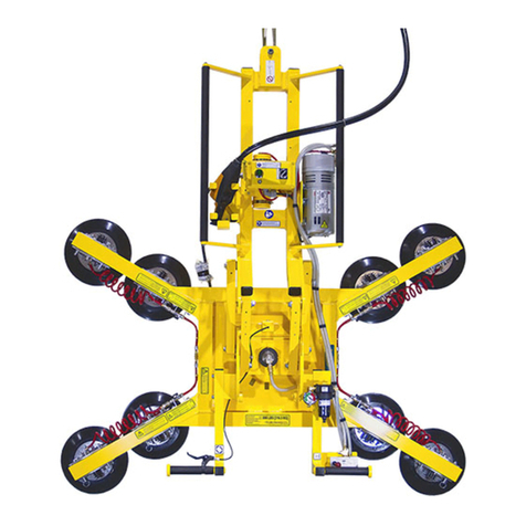
WPG N4950AIR User manual

KEEP FOR FUTURE REFERENCE
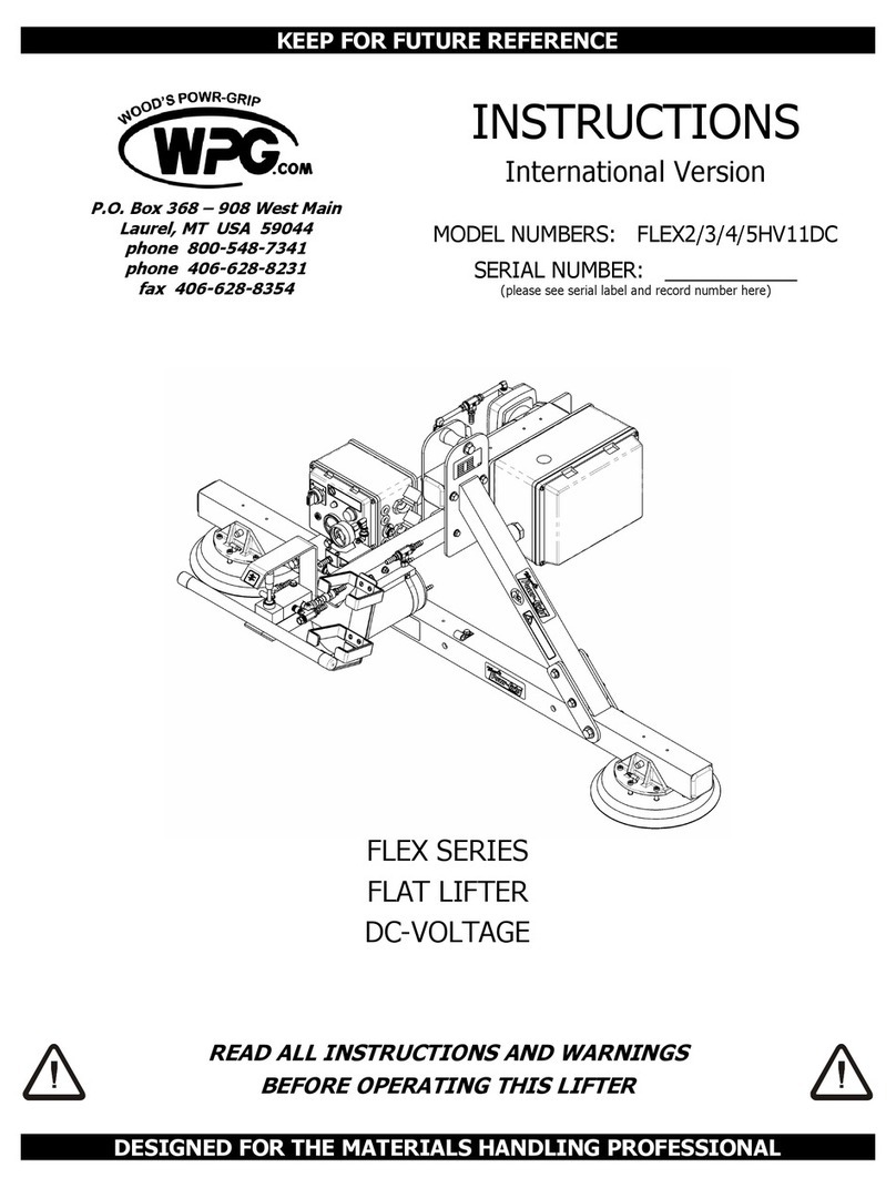
INSTRUCTIONS
International Version
MODEL NUMBERS: N4950AIR, N10TAIR
SERIAL NUMBER: ___________
(please see serial label and record number here)
HAND-HELD VACUUM CUP
AIR-POWERED
READ ALL INSTRUCTIONS AND WARNINGS
BEFORE OPERATING THIS HAND CUP
DESIGNED FOR THE MATERIALS HANDLING PROFESSIONAL
P.O. Box 368 –908 West Main
Laurel, MT USA 59044
phone 800-548-7341
phone 406-628-8231
fax 406-628-8354


Rev 4.0/8-17 1 N4950/N10TAIR: #35105
TABLE OF CONTENTS
SPECIFICATIONS............................................................................................................ 2
WARNINGS ..................................................................................................................... 3
OPERATING FEATURES................................................................................................... 4
ASSEMBLY....................................................................................................................... 5
INTENDED USE ............................................................................................................... 6
LOAD CHARACTERISTICS ............................................................................................................. 6
OPERATING ENVIRONMENT .........................................................................................................7
DISPOSAL OF THE HAND CUP .......................................................................................................7
OPERATION .................................................................................................................... 8
BEFORE USING THE HAND CUP.....................................................................................................8
Taking Safety Precautions ............................................................................................................................8
TO ATTACH THE HAND CUP TO A LOAD........................................................................................... 8
TO LIFT AND MOVE THE LOAD ......................................................................................................9
About the Red-Line Vacuum Indicator ...........................................................................................................9
Lifting the Load ...........................................................................................................................................9
Monitoring the Red-Line Vacuum Indicator ....................................................................................................9
In Case of Power Failure ..............................................................................................................................9
TO RELEASE THE HAND CUP FROM THE LOAD ................................................................................ 10
AFTER USING THE HAND CUP.....................................................................................................10
MAINTENANCE.............................................................................................................. 11
INSPECTION SCHEDULE.............................................................................................................11
Every-Lift Inspection ..................................................................................................................................11
Frequent Inspection ...................................................................................................................................11
Periodic Inspection ....................................................................................................................................11
Infrequent Use ..........................................................................................................................................11
TESTING SCHEDULE..................................................................................................................12
MAINTENANCE SCHEDULE .........................................................................................................12
VACUUM PAD MAINTENANCE ..................................................................................................... 12
Friction Coefficient .....................................................................................................................................12
Pad Inspection...........................................................................................................................................12
Pad Cleaning .............................................................................................................................................13
TO REPLACE SEALING RING INSERT IN VPFS10T PADS.................................................................14
REPLACEMENT PARTS LIST .......................................................................................... 15
LIMITED WARRANTY.................................................................................................... 16

Rev 4.0/8-17 2 N4950/N10TAIR: #35105
SPECIFICATIONS
Description:
Designed for use with a compressed air supply, these N-Series hand cups
employ vacuum for attaching to loads, which are manually lifted and
carried, offering a wide range of handling options.
Model Number:
N4950AIR
N10TAIR
Vacuum Pad / Pad Spread:
8" [20 cm] nominal diameter
(Model G0695)
10" [25 cm] nominal diameter
(Model VPFS10T1)
(one of standard rubber with #60 filter screen)
Maximum Load Capacity:
125 lbs [57 kg]
150 lbs [68 kg]
(rated at 16" Hg [-54 kPa] on clean, smooth, nonporous flat surfaces2)
Hand Cup Weight:
3 lbs [1.36 kg]
5.25 lbs [2.38 kg]
Power Source:
Compressed air, 70-80 psi [483-552 kPa] line pressure, 2 SCFM [57
liters/minute] @ 75 psi [517 kPa]
Vacuum Pump:
Venturi type, 1 SCFM [28 liters/minute] nominal vacuum flow @ 75 psi
[517 kPa]
Vacuum Indicator:
When hidden, red line on plunger indicates current vacuum level is
adequate for lifting a load.
Operating Elevation:
Maximum = 9000 feet [2743 meters]
Operating Temperatures:
10° to 120° F [-12° to 49° C]
Service Life:
This hand cup is designed to have a service life of at least 20,000 lifting
cycles, when used and maintained as intended. Vacuum pads and other
wear-out items are excluded (see MAINTENANCE and REPLACEMENT
PARTS LIST for more information). For the DISPOSAL OF THE HAND CUP after
its service life, see INTENDED USE.
1
The replaceable sealing ring on this vacuum pad is used for applications on rough or textured surfaces (see REPLACEMENT
PARTS LIST).
2
Load Capacity is based on a friction coefficient of 1; see MAINTENANCE: VACUUM PAD MAINTENANCE: Friction Coefficient for
additional information.

Rev 4.0/8-17 3 N4950/N10TAIR: #35105
WARNINGS
Powr-Grip is pleased to offer the most reliable hand-held vacuum cups
available. Despite the high degree of security provided by this product, certain
precautions must be observed to protect the operator and others.
Always
wear personal protective equipment that is appropriate for the material being handled.
Follow trade association guidelines.
Never
attach the hand cup to hoists or any other lifting device. It is designed for manual use
only.
Always
operate the hand cup under conditions approved for its design (see INTENDED USE:
OPERATING ENVIRONMENT).
Never
operate a hand cup that is damaged, malfunctioning, or missing parts.
Never
operate a hand cup if the sealing edge of the vacuum pad is cut or otherwise damaged.
Always
make certain the contact surfaces of the load and the vacuum pad are clean prior to
attaching the pad (see MAINTENANCE: VACUUM PAD MAINTENANCE).
Never
exceed the Maximum Load Capacity or attempt to lift loads the hand cup is not designed
for (see INTENDED USE: LOAD CHARACTERISTICS).
Never
attempt to lift cracked or broken glass with this hand cup.
Always
position the vacuum pad correctly on the load prior to lifting (see OPERATION: TO
ATTACH THE HAND CUP TO A LOAD).
Never
lift a load when the red-line vacuum indicator is visible.
Never
touch the vacuum release button during a lift. This would result in loss of vacuum and
immediate release of the load.
Never
use the hand cup to support a person.
Always
position yourself and others to avoid injury in the event of an unexpected load release.
Always
remember that modifications to the hand cup may compromise its safety. Wood’s Powr-
Grip cannot be responsible for the safety of a hand cup that has been modified by the
customer. For consultation, contact Wood's Powr-Grip (see LIMITED WARRANTY).

Rev 4.0/8-17 4 N4950/N10TAIR: #35105
OPERATING FEATURES
Note: Components featured in the following instructions for assembling, operating or
maintaining the hand-held vacuum cup are underlined on their first appearance in each section.
Standard N4950AIR shown.
1) VACUUM PAD
5) VACUUM RELEASE BUTTON
2) PLUNGER
6) VACUUM PUMP (VENTURI)
3) RED-LINE VACUUM INDICATOR
7) 1/8" NPT MALE FITTING
4) HANDLE

Rev 4.0/8-17 5 N4950/N10TAIR: #35105
ASSEMBLY
1) Remove the hand-held vacuum cup from its carrying case or remove the pad cover,
depending on the model. Save the case or cover for use whenever the hand cup is
transported or stored.
2) Connect the hand cup's vacuum pump to an appropriate compressed air supply (see
SPECIFICATIONS: Power Source), as follows:
3
Use appropriate hose and/or fittings to connect an air line from the compressed air supply to
the 1/8" NPT male fitting on the hand cup.
WARNING: Any damage or obstruction in air line would result in immediate load
release.
Make certain the air line is routed so that it does not become tangled, kinked, pinched or cut
while operating the hand cup or production machinery. Any damage or obstruction in the air
line would result in an immediate load release and possible injury to the operator.
3) Adjust the air pressure regulator to supply a continuous air pressure of 70 to 80 psi [483 to
552 kPa]. Exceeding this pressure does not improve the vacuum flow or performance of the
hand cup. Pressures greater than 80 psi [552 kPa] should be avoided. Now the hand cup is
operational.
4) Perform tests of the hand cup as directed in MAINTENANCE: TESTING SCHEDULE.
3
The hand cup will continue to consume air as long as it is connected to the compressed air supply. A quick connector type
fitting may be installed in the air line, if frequent connecting and disconnecting of the hand cup is desired.

Rev 4.0/8-17 6 N4950/N10TAIR: #35105
INTENDED USE
LOAD CHARACTERISTICS
WARNING: This hand cup is NOT intended for lifting hazardous materials, such
as explosives or radioactive substances.
The operator must verify that the hand cup is intended to handle each load, in accordance with
the following requirements:
• The load must not exceed the allowable weight specified under Maximum Load Capacity (see
SPECIFICATIONS).
• The load must be a single piece of nonporous or semiporous material with a flat and relatively
smooth contact surface.
4
To determine whether the load is too porous or rough, simply
attach the hand cup to the contact surface (see OPERATION: TO ATTACH THE HAND CUP TO A
LOAD) and determine whether the red-line vacuum indicator would remain hidden during a lift
(see OPERATION: TO LIFT AND MOVE THE LOAD: About the Red-Line Vacuum Indicator). If not,
the load does not possess the characteristics required for using this hand cup.
• The load's contact surface must be suitable for obtaining a friction coefficient of 1 with the
hand cup's vacuum pad (see MAINTENANCE: VACUUM PAD MAINTENANCE: Friction Coefficient),
as verified by a friction test. If necessary, contact Wood's Powr-Grip for help in conducting a
friction test.
• In order to avoid damaging the vacuum pad, the load's surface temperature must not exceed
the allowable Operating Temperatures (see SPECIFICATIONS). However, if such an
application cannot be avoided, Wood's Powr-Grip does offer a heat-resistant rubber
compound and other solutions which may enable you to lift loads with higher surface
temperatures. Contact Wood’s Powr-Grip or an authorized dealer for more information.
•While the
minimum
length and width of the load are determined by the Pad Spread (see
SPECIFICATIONS), the
maximum
length and width are determined by the allowable
overhang, or the amount of load material that can extend sideways beyond the vacuum pad
without breaking or otherwise being damaged.
The allowable overhang depends on the kind of load material being lifted, the thickness of the
material, and the angle at which it is handled (if any). Since materials such as glass, stone or
sheet metal each have different physical properties, the allowable overhang must be
evaluated separately for each type of load. If necessary, contact Wood’s Powr-Grip or an
authorized dealer for help in determining the recommended overhang in a specific situation.
• Although the thickness of the load is not restricted for this hand cup, load thickness may affect
the angle of load orientation and the amount of operator effort required for handling loads.
Note: Vacuum pads can stain or deform load surfaces with light colors or soft coatings. The
operator should test such surfaces for detrimental effects before using the hand cup on them.
4
Hand cups that feature concave vacuum pads can also attach to some kinds of curved loads. Since curvature affects the lifting
capacity, contact Wood’s Powr-Grip for help in determining the Load Capacity for a particular curved load.

Rev 4.0/8-17 7 N4950/N10TAIR: #35105
OPERATING ENVIRONMENT
The operator must determine whether the hand cup is intended to be used in each work
environment, in accordance with the following restrictions:
WARNING: Never use hand cup in dangerous environments.
• This hand cup is not intended for use in any environment that is inherently dangerous to the
operator or likely to compromise the hand cup's ability to function. Environments containing
explosives, caustic chemicals and other dangerous substances must be avoided when using
the hand cup.
• The hand cup's work environment is limited by the Operating Elevation and Operating
Temperatures indicated in SPECIFICATIONS.
• Using the hand cup in wet environments may require the operator to take special precautions:
Moisture on contact surfaces of the load or the vacuum pad diminishes the hand cup’s slip
resistance, thereby reducing the lifting capacity (see MAINTENANCE: VACUUM PAD
MAINTENANCE: Friction Coefficient).
WARNING: Moisture reduces slip resistance of vacuum pad.
Although the hand cup's exterior surfaces can tolerate some exposure to water vapor, they
are not designed to be water-tight. Submerging the hand cup or using it in rain may damage
hand cup components; these and similar conditions must be avoided.
DISPOSAL OF THE HAND CUP
After the hand cup has reached the end of its service life, dispose of the hand cup in compliance
with all local codes and regulatory standards that are relevant for the geographical region.

Rev 4.0/8-17 8 N4950/N10TAIR: #35105
OPERATION
BEFORE USING THE HAND CUP
The operator must determine whether the hand cup is capable of performing each intended task,
in accordance with the SPECIFICATIONS and INTENDED USE sections of this
INSTRUCTIONS
manual. In addition, the operator must perform all inspections and tests required by the
INSPECTION and TESTING SCHEDULES (see MAINTENANCE) and take all of the following safety
precautions prior to lifting any load.
Taking Safety Precautions
The operator must be trained in all relevant industry and regulatory standards for the use of the
hand cup in its geographical location (eg, relevant OSHA Standards in the USA).
The operator must read and understand this
INSTRUCTIONS
manual, including all
WARNINGS
,
before using the hand cup. If necessary, contact Wood’s Powr-Grip or an authorized dealer for
assistance.
WARNING: Always wear appropriate personal protective equipment.
The operator must wear any personal protective equipment and take any other precautions
required to handle the load safely. Consult appropriate trade association guidelines to determine
what precautions are necessary for each type of load material.
TO ATTACH THE HAND CUP TO A LOAD
WARNING: Never interrupt vacuum flow while operating hand cup; keep pump
running throughout lift.
The hand cup is designed for the vacuum pump to run continuously. Any interruption of the
vacuum flow during hand cup operation would result in the immediate release of the load and
possible injury to the operator (see ASSEMBLY and TO LIFT AND MOVE THE LOAD: In Case of Power
Failure to follow). Make certain that the contact surfaces of the load and vacuum pad are free of
any contaminates that could prevent the pad from sealing against the load (see MAINTENANCE:
VACUUM PAD MAINTENANCE).
Position the hand cup on the load so as to maximize stability while lifting the load. For sheet
materials, determine which will be the upper edge of the load when it is lifted, and position the
vacuum pad near that edge, centering the pad from left to right. Make sure that the vacuum pad
will fit entirely on the load’s contact surface (see SPECIFICATIONS: Vacuum Pad / Pad Spread).
Then gently press the hand cup onto the load until the pad seals against the contact surface.
Note: If the vacuum pad has been lying against a hard object, it may be slightly distorted.
Although initially it may be difficult to apply the pad to a load, this condition should correct itself
with continued use.

Rev 4.0/8-17 9 N4950/N10TAIR: #35105
TO LIFT AND MOVE THE LOAD
About the Red-Line Vacuum Indicator
The hand cup is equipped with a red line on the plunger, which serves as a vacuum indicator.
When the red-line vacuum indicator is hidden within the hand cup's handle, this indicates that
the vacuum level is adequate for lifting a load.
WARNING: Never attempt to lift load when red-line indicator is visible.
Do not attempt to lift a load while the red-line indicator is visible; such an attempt could result in
a load release and possible injury to the operator.
Lifting the Load
Once the hand cup is attached and the red-line vacuum indicator is hidden, grasp the handle and
use correct lifting technique to raise the load as needed to clear any obstacles while you are
moving the load.
WARNING: Position yourself and others to avoid injury in event of unexpected
load release.
Even if the red-line indicator remains hidden, always position yourself and others so as to avoid
injury in the event of an unexpected load release.
Monitoring the Red-Line Vacuum Indicator
The plunger of the hand cup must remain visible to the operator, so that the red-line vacuum
indicator can be monitored throughout the entire lift. If the hand cup experiences leakage, its
red-line indicator becomes visible, to signal the reduction in vacuum to the operator.
WARNING: Monitor red-line indicator throughout entire lift.
Check the red-line indicator frequently to make sure the vacuum pad is attached securely. If the
red-line indicator becomes visible while you are lifting a load, immediately lower the load to the
ground or a stable support.
WARNING: Set load down immediately if red-line indicator becomes visible.
Discontinue hand cup use until the cause of the vacuum loss can be determined. If it is caused
by contamination, thoroughly clean the contact surfaces of the load and the vacuum pad (see
MAINTENANCE: VACUUM PAD MAINTENANCE: Cleaning), and reattach the hand cup to the load. If
the red-line indicator remains visible when the hand cup is attached to clean, smooth, nonporous
materials, either the hand cup or the compressed air supply requires service or repair. Inspect
the vacuum pad for damage (see MAINTENANCE: VACUUM PAD MAINTENANCE: Inspection) and
replace it when necessary. Perform inspection and maintenance as needed to identify and
correct any deficiency before resuming normal operation of the hand cup.
In Case of Power Failure
WARNING: Set load down immediately in event of power failure.
A power failure at the compressed air supply could result in the release of the load and possible
injury to the operator, unless action is taken immediately: In the event of a power failure, lower
the load immediately to the ground or a stable support, and discontinue hand cup use until
power is restored.

Rev 4.0/8-17 10 N4950/N10TAIR: #35105
TO RELEASE THE HAND CUP FROM THE LOAD
WARNING: Load must be fully supported before releasing vacuum pad.
Use correct lifting technique to lower the load to the ground or a stable support. When the load
is at rest and fully supported, push the vacuum release button until the vacuum pad disengages
completely from the load. Then move the hand cup away. Continue to hold the release button
until the pad is well away from the load; otherwise, the hand cup would reattach itself to the
load.
AFTER USING THE HAND CUP
Disconnect the hand cup from the compressed air line or turn off the compressed air supply, as
appropriate.
CAUTION: Do not set the hand cup against any surfaces which could soil or damage
the vacuum pad.
Use the carrying case or pad cover when storing the hand cup or transporting it to another
location.

Rev 4.0/8-17 11 N4950/N10TAIR: #35105
MAINTENANCE
INSPECTION SCHEDULE
Perform inspections routinely, according to the following frequency schedule:
Every-Lift Inspection
• Examine the vacuum pad and load surface for contamination or debris (see VACUUM PAD
MAINTENANCE to follow).
• Examine the vacuum pad, red-line vacuum indicator and other OPERATING FEATURES for
visual damage (see VACUUM PAD MAINTENANCE to follow).
If any deficiency is detected during the inspection, correct it before using the hand cup and
perform the Frequent Inspection to follow.
Frequent Inspection
(
following every 20-40 hours’ use; or whenever hand cup is out of service for 1 month or more
)
• Examine the hand cup’s structure for visual damage.
• Examine the air supply system (including fittings and hoses) for visual damage.
• Check for unusual vibrations or noises while operating the hand cup.
If any deficiency is detected during the inspection, correct it before using the hand cup and
perform the Periodic Inspection to follow.
Periodic Inspection
(
following every 250-500 hours’ use; or whenever hand cup is out of service for 1 year or more
)
• Examine the entire hand cup for external evidence of looseness, excessive wear, deformation,
cracks, excessive corrosion, dents to structural or functional components, cuts, or any
deficiency which might constitute a hazard.
• Keep a written record of all Periodic Inspections.
If any deficiency is detected during the inspection, return the hand cup to Wood’s Powr-Grip or
an authorized dealer for repair (see LIMITED WARRANTY).
Infrequent Use
If a hand cup is used less than 1 day in a 2-week period, perform the Periodic Inspection
each
time before using the hand cup
.

Rev 4.0/8-17 12 N4950/N10TAIR: #35105
TESTING SCHEDULE
Perform these tests when placing the hand cup in service
initially
and
each time following a repair
or modification
. Test all features and functions of the hand cup (see OPERATING FEATURES,
OPERATION and MAINTENANCE). Correct any deficiency and retest before using the hand cup.
Note: See MAINTENANCE topics to follow for additional directions about inspecting and testing
specific hand cup components.
MAINTENANCE SCHEDULE
Unless specified elsewhere in this
INSTRUCTIONS
manual, the hand cup does not require
maintenance on a routine basis. Instead, maintenance must be performed whenever a
deficiency is indicated by routine inspections or tests. Any maintenance warranted must be
performed before resuming normal operation of the hand cup.
VACUUM PAD MAINTENANCE
Friction Coefficient
The friction coefficient represents the hand cup's ability to resist load slippage when the load is
oriented in any position except horizontal. If the contact surface of either the load or the
vacuum pad is not clean, dry and in good condition, slippage is more likely to occur.
The Maximum Load Capacity of this hand cup is based on a friction coefficient of 1. However, a
vacuum pad's ability to maintain this friction coefficient is reduced by factors such as
contamination, wear, age and exposure to sunlight, as well as the condition of the load's contact
surface (see INTENDED USE: LOAD CHARACTERISTICS). A pad that has surface contamination must
be thoroughly cleaned (see Cleaning discussion to follow). Over time, the rubber in a pad may
experience hardening or leaching of chemicals, resulting in stiffness or surface glaze. A pad that
exhibits wear, stiffness or glaze must be replaced.
In addition, every pad should be replaced on a regular basis, preferably after no more than 2
years, to ensure that the friction coefficient is not compromised. If necessary, contact your
dealer or Wood's Powr-Grip for more information.
Pad Inspection
Inspect the vacuum pad for the following deficiencies routinely, as directed in the preceding
INSPECTION and TESTING SCHEDULES. Correct any deficiency before using the hand cup.
• Contaminates on the pad face or sealing edges: Soil build-up can prevent a pad from sealing
adequately or reduce the friction coefficient (see discussion preceding). Follow the directions
to clean the pad as necessary (see discussion to follow).
• Filter screen missing from pad face: This screen helps prevent debris from plugging the air
inlet. Replace any missing screen immediately (see REPLACEMENT PARTS LIST).

Rev 4.0/8-17 13 N4950/N10TAIR: #35105
• Nicks, cuts or abrasions in sealing edges: Pad damage can reduce the lifting capacity of the
hand cup. Replace any damaged pad immediately (see REPLACEMENT PARTS LIST).
5
WARNING: Replace vacuum pad if sealing edge has any nicks, cuts or abrasions.
• Wear, stiffness or glaze: See Friction Coefficient preceding. Replace any pad that exhibits
wear, stiffness or glaze (see REPLACEMENT PARTS LIST).
Pad Cleaning
Regularly clean the face of each vacuum pad to remove oil, dust and any other contaminates.
Acceptable cleaning agents include soapy water and other mild cleansers. Do
not
use solvents,
petroleum-based products (including kerosene, gasoline and diesel fuel) or any harsh chemicals
for cleaning. Do
not
use unauthorized rubber cleaners or conditioners, such as those intended
for cleaning tires or vinyl surfaces, because those products can leave a hazardous film on vacuum
pads which significantly reduces their lifting capacity (see Friction Coefficient preceding). The
use of any unauthorized cleaning agent is prohibited because it could damage the pad and/or
create a hazard to the operator or others.
WARNING: Never use solvents, gasoline or other harsh chemicals to clean
vacuum pad.
WARNING: Never use unauthorized rubber cleaners or conditioners to clean
vacuum pad.
To prevent liquid from contaminating the hand cup during cleaning, cover the suction hole in the
recess for the filter screen or make sure the pad faces downward. Use a clean sponge or lint-
free cloth to apply an authorized cleanser and wipe the pad face clean. A toothbrush (or similar
brush with bristles
that do not harm rubber
) may be used to remove contaminates clinging to
sealing edges.
6
Wipe all residue from the pad face, and allow the pad to dry completely before
using the hand cup.
5
If the hand cup is equipped with a VPFS10T pad, the sealing edge is the replaceable sealing ring. When it is damaged, install a
new sealing ring insert. In such cases, see TO Replace Sealing Ring Insert in VPFS10T Vacuum Pads.
6
If these cleaning methods are not successful, contact Wood’s Powr-Grip or an authorized dealer for assistance.

Rev 4.0/8-17 14 N4950/N10TAIR: #35105
5
4
3
2
1
TO REPLACE SEALING RING INSERT IN VPFS10TPADS
If the lifter is equipped with VPFS10T vacuum pads,
replace the sealing ring insert (see REPLACEMENT PARTS
LIST) as shown:
1) Remove the old sealing ring insert.
Make sure the entire vacuum pad is clean, including
the mounting groove (see VACUUM PAD MAINTENANCE:
Pad Cleaning preceding).
2) Place the inside edge of a new sealing ring insert
against the inside edge of the mounting groove.
3) Push the sealing ring insert into the mounting groove,
beginning in 4 locations as shown.
4) Push gently and firmly on the outside edge of the ring
insert until its base (flat side) fits flush against the
bottom of the mounting groove. A pad ring installation
tool is available to facilitate this process (see
REPLACEMENT PARTS LIST).
5) Make sure that the sealing ring seats completely and
securely in the mounting groove, around the entire
perimeter of the vacuum pad.
Note: If the ring insert ever comes partially or entirely out
of the mounting groove, inspect the ring insert for
damage and reinstall an undamaged ring insert according
to preceding directions.

Rev 4.0/8-17 15 N4950/N10TAIR: #35105
REPLACEMENT PARTS LIST
Stock No.
Description
Qty.
90520
Plunger Assembly
1
90510
Handle
1
66155
Venturi Insert (aka, vacuum pump)
1
49724TT
Sealing Ring Insert –Model VIFS10T2 –Closed Cell Foam (for VPFS10T pad)
1
49724RT
Sealing Ring Insert –Model VIFS10T3 –Heat-Resistant Rubber (for VPFS10T pad)
1
49672FT
Vacuum Pad –Model VPFS10T / 10" [25 cm] Diameter –w/Replaceable Sealing Ring
1
49486T
Vacuum Pad –Model G0695 / 8" [20 cm] Diameter
1
29353
Pad Cover (for N10TAIR)
1
29334
Case –Black –8" [20 cm] (for N4950AIR)
1
20050
Pad Ring Installation Tool (for VPFS10T pad)
1
15632
Pad Filter Screen –Small
1
10002
Screw –1/4-20 x 1/2"
6
SERVICE ONLY WITH IDENTICAL REPLACEMENT PARTS,
AVAILABLE AT WPG.COM OR THROUGH AN AUTHORIZED WPG DEALER

Rev 4.0/8-17 16 N4950/N10TAIR: #35105
LIMITED WARRANTY
Powr-Grip products are carefully constructed, thoroughly inspected at various stages of
production, and individually tested. They are warranted to be free from defects in workmanship
and materials for a period of one year from the date of purchase.
If a problem develops during the warranty period, follow the instructions hereafter to obtain
warranty service. If inspection shows that the problem is due to defective workmanship or
materials, Powr-Grip will repair the product without charge.
WARRANTY DOES NOT APPLY WHEN:
Modifications have been made to the product after leaving the factory.
Rubber portions have been cut or scratched during use.
Repairs are required due to abnormal wear and tear.
The product has been damaged, misused, or neglected.
If a problem is not covered under warranty, Powr-Grip will notify the customer of costs prior to
repair. If the customer agrees to pay all repair costs and to receive the repaired product on a
C.O.D. basis, Powr-Grip then will proceed with repairs.
Wood's Powr-Grip Co., Inc.
908 West Main St. / P.O. Box 368
Laurel, MT USA 59044
phone 800-548-7341
phone 406-628-8231
fax 406-628-8354
TO OBTAIN REPAIRS OR WARRANTY SERVICE
For purchases in
North America
:
Contact the Technical Service Department at Wood’s Powr-Grip Co. When factory service
is required, ship the complete product--prepaid--along with your name, address and
phone number to the street address hereafter.
For purchases in
all other localities
:
Contact your dealer or the Technical Service Department at Wood’s Powr-Grip Co. for
assistance.
This manual suits for next models
1
Table of contents
Other WPG Lifting System manuals

WPG
WPG MT410TAIR User manual

WPG
WPG QUADRA-TILT MRTA811LDC3 User manual

WPG
WPG FL1HV11DC User manual

WPG
WPG MRTALPCH611LDC Reference guide

WPG
WPG VL411LDC User manual

WPG
WPG MRT49DC User manual

WPG
WPG MTCL8FS10TDC User manual

WPG
WPG FLEXR Series User manual

WPG
WPG PT10FS10TAC User manual

WPG
WPG P1HV1102DC3 User manual