LSM V50 Assembly instructions

SERIAL NO:
INSTALLATION DATE:
CE Certified
EN16500 Compliant
www.lsmltd.com Keep these instructions for future use!
OPERATOR INSTRUCTION MANUAL
V50 Mill Size Baler

2

3
Index
Contents Page No.
Introduction 4
Preparing baler for transport 5
Loading / Unloading baler 6
Machine installation 7
Baler Foot Print 7
V50 Ram Installation Procedure 8-13
Exact power requirements 14
Customer responsibilities 14
End of life 14
Designated Use of Machine 15
Safe operation zone 16
Emergency Stop Locations 17
Specifications
Technical Data 18
Compactor and Bale Specifications 19-20
Warranty
Warranty Registration Forms 21
Warranty 25
Safety
General Safety 26
Safety Checklist 26
Control Panel Description 27
Operation Instructions
Machine decal explanation 28
A. Preparation prior to loading 29-31
B. Loading the Baler (Instructions Diagram) 32-33
C. Tying and removing the bale 34-38
Troubleshooting 39
Care and Maintenance 40
Parts List 41-43
Terms and Conditions 44
Declaration 45
Installation/ Training 46
LSM Training Record 47-50
Electrical and Hydraulic Diagrams 51-57

4
Introduction
Congratulations on your purchase of an LSM V50 BALER.
PLEASE READ THE FOLLOWING MANUAL BEFORE USING THE MACHINE.
Read this manual carefully for instructions on how to operate your Material Baler correctly.
In order for you to achieve the best possible results with your new Material Baler, we kindly
ask you to study the following pages carefully before use.
Please complete the specification and warranty sheets immediately after purchase.
Remember! Warranty forms must be returned to us fully completed within 30 days of
purchase. Warranty registration forms can be faxed to LSM. Failure to do so can result in
loss of warranty for your machine.
This manual has been carefully written to help you maintain the condition of your machine.
Please adhere to the recommended maintenance instructions to prolong the life of your
machine.
Keep safety in mind at all times. Failure to do so could result in personal injury or
damage to your machine.
All information, illustrations and specifications in this manual are based on the latest
information available at the time of publication.
It is the policy of LSM Engineering Ltd. to improve its products whenever possible and
practical to do so. We reserve the right to make changes or improvements at any time
without incurring any obligation to make such changes on products sold.
Thank you for choosing LSM.

5
Preparing the baler for transportation
Before transporting your baler please perform these basic checks to avoid injury to persons or
damage to your machine.
Check that all doors are closed and latched
Any trailing cables are tidied away
The oil bung is in the tank
All parts are bolted down parts are tight
Any loose parts are placed inside the baler
Moving the baler
Please take into consideration the centre of gravity of the machine when moving as it is high
(shown by the black spot on the diagram below). This makes the machine unstable and top
heavy. Take care to ensure that there are no personnel in the vicinity during the lifting process
and only trained personnel to perform lifting duties.
Moving the baler should only be done via the use of a forklift or pallet truck. Do not ‘drag’ the
machine around by hand as this could cause injury to you, or damage to the machine.
When lifting a baler the forks or pallet truck should be inserted in the gap in the base as shown
below (approx weights 1760kg’s).
CENTRE OF GRAVITY
FRONT VIEW END VIEW

6
Loading / Unloading the baler
Carefully lift the machine on to the trailer. If transporting a single baler place it on the centre of
the trailer over the axle to maintain trailer balance during transport.
If transporting multiple balers lift them onto the trailer via a fork truck. Carefully position the
balers so that the weight is evenly distributed over the trailer, this will provide extra stability
during transport.
UNDER NO CIRCUMSTANCES SHOULD A BODY OR BODY PART BE UNDER THE
MACHINE DURING LOADING OR MOVING
When the baler or balers are in position on the trailer they should be tied down using a
minimum of 2 ratchet straps. The baler comes equipped with tie down positions on the top four
corners, pick the front tie position on one side and the rear one on the other.
When unloading the baler the same procedure applies as when loading.
RATCHET STRAP
TIE POSITIONS

7
Machine Installation
Although the baler is suitable for outside use it is recommended that it is located inside or under
a protective cover. Doing so will extend the life of your machine.
It is important to know how to safely move your machine into position. To do this use either a fork
truck or a pallet truck and lift the machine via the base (page 5.) Do not attempt to move the
machine by hand as this could cause injury to you or damage the machine, in part due to the
machines high centre of gravity.
Fix your machine to a solid level surface to avoid toppling or movement while in operation.
Brackets are provided with to the baler so it can be screwed into sound concrete ground. Use
with proper fixings (M12 rawl bolts if fixing to concrete) and bolt down on either the 4 corners of
the base as shown in below.
Baler Footprint
M12 ANCHOR BOLTS
FITTED TO FLOOR
BRACKETS PROVIDED
M12 ANCHOR BOLTS x 2

8
V50 Ram Installation Procedure
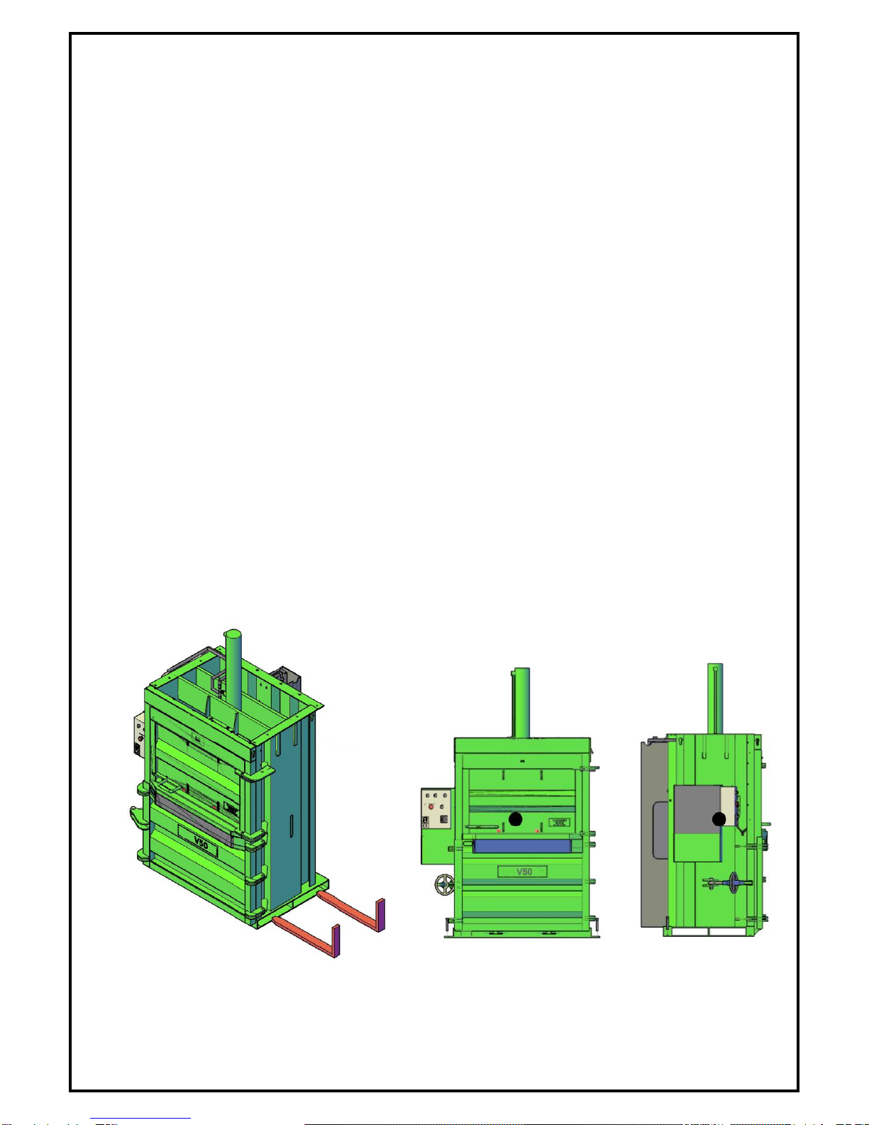
When you receive your V50 machine, the ram will be dropped into the machine’s chamber for
transport purposes (Fig 1). This procedure outlines the steps to be taken to re-fit the ram and
centreplate back into its operating position. It also outlines the steps to be taken to lower the ram
and centreplate if the machine has a requirement to be transported again for any reason.
To fit the ram back to its housing, carry out the following steps;
1) Plug in machine and turn on. (Check motor rotation is correct or machine will only run but not
develop pressure)
2) Make sure the doors are closed.
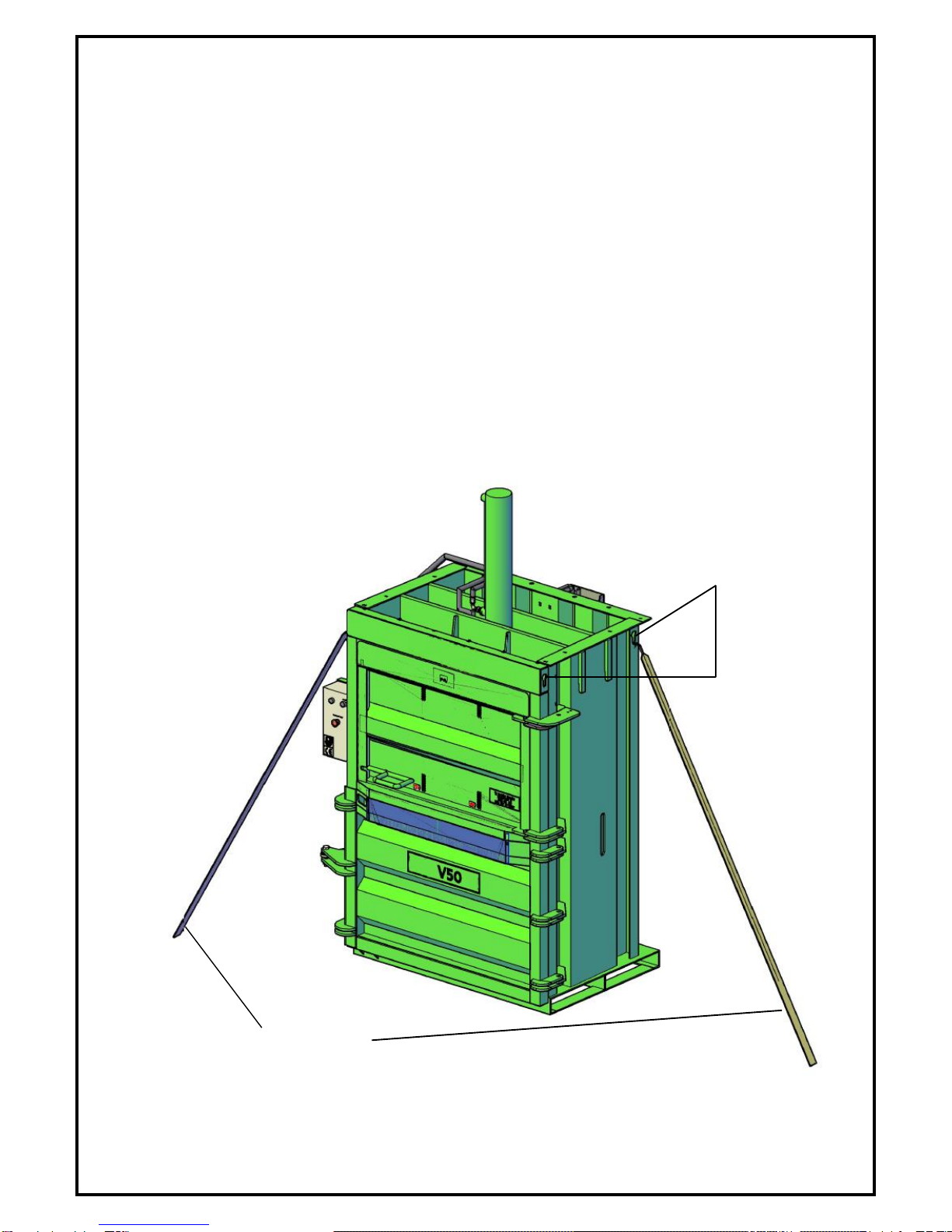
3) Before moving the centreplate, ensure the ram is orientated so that the hoses and fittings will
not get caught on the machine.
4) On the control panel press and hold the DOWN button (See page 27 for button location if
unsure.) This will move the centreplate ram up as it is resting on four steel brackets (fig 3).
Stop pressing the button every couple of seconds and open the topdoor to check ram position
(fig 2). Always keeping an eye on hydraulic pipes and making sure they do not become
trapped or get cut.
WARNING! IF THE UP BUTTON IS PRESSED THE
HYDRAULIC HOSES WILL GET DAMAGED OR CUT OFF.
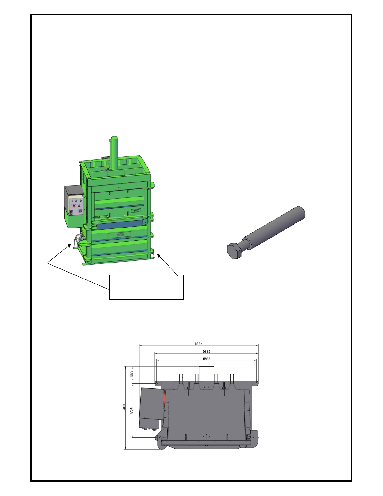
5) Continue to press the DOWN button until the ram has reached the end of its travel and is
approximately 5mm away from the mounting bracket.
6) When the ram base plate has reached the end of its travel and is approximately 5mm away
from the mounting bracket, activate the emergency stop button. (See page 27 for button
location if unsure.)
7) Disconnect the power running to the machine.
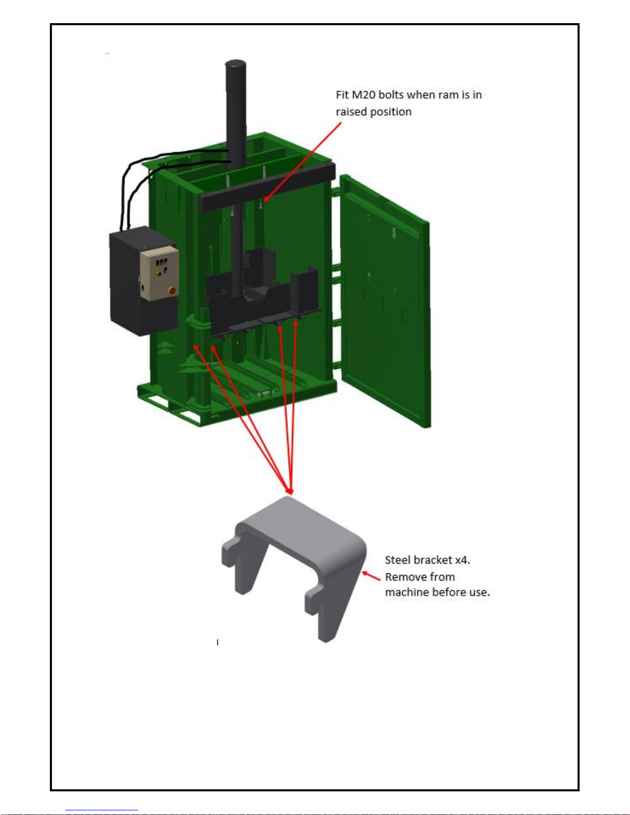
Fit M20 bolts up from the bottom (nuts on top) and tighten (fig 2). You may need to adjust the ram
position to line up the bolt holes. Ensure when tightened that the ram plate is in contact with the
mounting bracket.
**Remove 4 steel brackets from machine chamber (fig 3) **
Keep brackets with machine for future use.
You are now ready to start baling. Enjoy!
Note: Engineer should not enter machine at any
stage unless machine E-stop button is pressed and
machine is completely isolated at control panel and
at the power source. (IE. Plug and switch board).

9
Figure 1

10
Figure 2
Figure 3

11
To lower centreplate and ram for transport, carry out the following steps;
1) Ensure machine is plugged in and turned on. Also ensure the machine chamber is empty.
2) Place the four steel brackets into the slots in machine chamber (fig 4).
3) Close machine doors.
4) On the control panel press and hold the DOWN button (See page 21 for button location if
unsure.) This will move the centreplate down. Let it down until it is fully extended and the
centreplate is approx. 5mm above the four resting brackets (fig 5).
5) Carefully loosen the four M20 bolts on the ram plate. Loosen each bolt by half a turn in
sequence so that the ram and centreplate are gradually lowered rather than dropped onto the
brackets below.
6) When the ram plate has been disconnected from the mounting plate and is resting on the
brackets below, press the UP button. This will cause the ram to lower into the machine (fig 6).
7) Periodically open the doors and check the ram’s position.
8) WHEN THE RAM IS LOWERED SUFFICIENTLY SO THAT
THE HOSES CANNOT REACH ANY FURTHER, STOP! BE
CAREFUL NOT TO DAMAGE OR CUT THE HYDRAULIC
HOSES!
9) Disconnect the power running to the machine.
10)Open the machine doors and re-fit the 20mm bolts to the ram plate for safe keeping.
**Remove 4 steel brackets from machine chamber**
Keep brackets with machine for future use.
You are now ready to transport your machine.
Note: Engineer should not enter machine at any
stage unless machine E-stop button is pressed and
machine is completely isolated at control panel and
at the power source. (IE. Plug and switch board).

12
Figure 4
Figure 5

13
Figure 6

14
Exact power supply requirements for LSM
V50 Balers
Motor Size 7.5kW
1. 380/400V 3 phase and earth, 32amp per phase supply (neutral not required).
2. Supply should be protected by 32amp fuses (i.e. motor rated 32amps) or by a 32amp type
D circuit breaker.
3. The isolator/Plug should be positioned ideally within 2m of the machine.
4. If outdoors, the isolator/Plug should be waterproof to IP56 and we recommend it
incorporates a 30mA RCD.
5. 5 pin 32amp plug.
Customer responsibilities
When installing, operating and maintaining your baler the customer is responsible for:
Ensuring that the power requirements for the machine are satisfactory and that
installation of the plug and socket are carried out in accordance with the country of uses
electrical standards.
Ensuring that ALL personnel using the baler have read the operators manual and
understood all of the safety and operational procedures.
Ensuring that personnel have access to the operator’s manual at all times.
Ensuring that the electrical cable from the machine to the mains is located in a safe
position out of harm’s way and does not pose any hazards to the operator.
Ensuring that the baler is plugged directly to the mains supply without the use of an
extension cable.
Supplying M12x50 rawl or other suitable fixings to fix machine to the ground or wall.
Isolating power to the control panel to prevent unauthorised use.
End of life information
Your baler is primarily constructed from recyclable materials. When the machine has reached
end of life the below guidelines should be followed for safe and environmentally friendly
disposal.
Drain hydraulic oil. Collect in a container and bring to your local recycling centre for
disposal
Disassemble machine and sort into its separate materials.
Steel components can be sold to a scrap steel merchant.
All copper wire/electrical components/rubber/nylon should be brought to your local
recycling centre for disposal.

15
Designated Use of Machine
The Material Balers are exclusively designed as Material Balers to
compact only certain waste material. It is suitable ONLY to be
used with the following materials:
Cardboard, Paper, Plastic, Foam and Soft Materials.
The Material Baler is NOT SUITABLE for any of the following types
of waste:
Pressurised containers, Cans, Metal, Wood, Glass or any
Solid Materials.
LSM Engineering Ltd will not be held responsible for any loss or damage resulting from machine
applications other than those specified. Any other use the machine may be put to is entirely at
the owners / operators risk.
The designated use of an LSM Material Baler precludes that the operation, maintenance and
repair instructions as given by the manufacturer will be strictly fulfilled.
Any alterations made to this machine by the customer / user, especially interference with safety
guards and equipment could mean the Declaration of Conformity on this machine losing its
validity, as well as your warranty.
Noise Level Rating
Every care has been taken to ensure that the LSM range of balers have been designed to work
as efficiently and quietly as possible by using low noise emission components and vibration
dampening equipment..
The max decibel reading for the V50 baler range is 77dB. This falls below the max rating of
83dB after which ear protection is required.
Although ear protection is not required, LSM strongly recommend the use of ear protection
when operating their products.

16
Safe Operation Zone Ejection

17
Emergency Stop Location
EMERGENCY STOP LOCATION

18
Technical Data
V50
General
Compaction Force:
Up to 50T
Cycle Time:
45 Seconds
Door Type:
Swinging Door Standard
Guillotine Door Optional
Technical
Power Supply:
3 Phase (5 pin 32 Amp Plug)
Motor Size:
7.5Kw
User Controls:
24V Low Voltage Controls, Auto Cycle (Opt. Time Delay).
Hydraulics
Hydraulic Capacity:
40Lts
Pump Type:
Single System
Ram Size:
150 Bore with 80mm Rod

19
Individual Compactor and Bale Specifications (Swing door)
MACHINE SPEC.
V50
A. Operational Height
3055mm
B. Transport Height
2105mm
C. Loading Height
590mm
C. Width
1985mm
D. Depth
1130mm
E. Machine Weight Approx.
1760kg
BALE SPEC:
F. Height
1000mm variable
G. Width
1200mm
H. Depth
800mm
I. Bale Weight Approx (cardboard)
350-550kg
Machine Front Elevation Machine Side Elevation
Bale Dimensions

Individual Compactor and Bale Specifications (Guillotine door)
MACHINE SPEC.
V50
A. Operational Height
3055mm
B. Transport Height
2105mm
C. Loading Height
600mm
C. Width
1985mm
D. Overall Depth
1130mm
E. Machine Weight Approx.
1800kg
BALE SPEC:
F. Height
1000mm variable
G. Width
1200mm
H. Depth
800mm
I. Bale Weight Approx (cardboard)
350-550kg
Machine Front Elevation Machine Side Elevation
Bale Dimensions
Table of contents
Popular Industrial Equipment manuals by other brands

Elmo Rietschle
Elmo Rietschle Fieldbus Profibus 2FC4 1PB Series operating instructions

Dwyer Instruments
Dwyer Instruments DPG-000 Series Specifications-installation and operating instructions

Essemtec
Essemtec Paraquda Startup & Safety Manual

flamco
flamco FlexBalance EcoPlus C 1 Installation and operating instructions

ABB
ABB HT610226 Operation manual

Renishaw
Renishaw HPGA Installation and user guide