Installation/Use/Maintenance Instructions
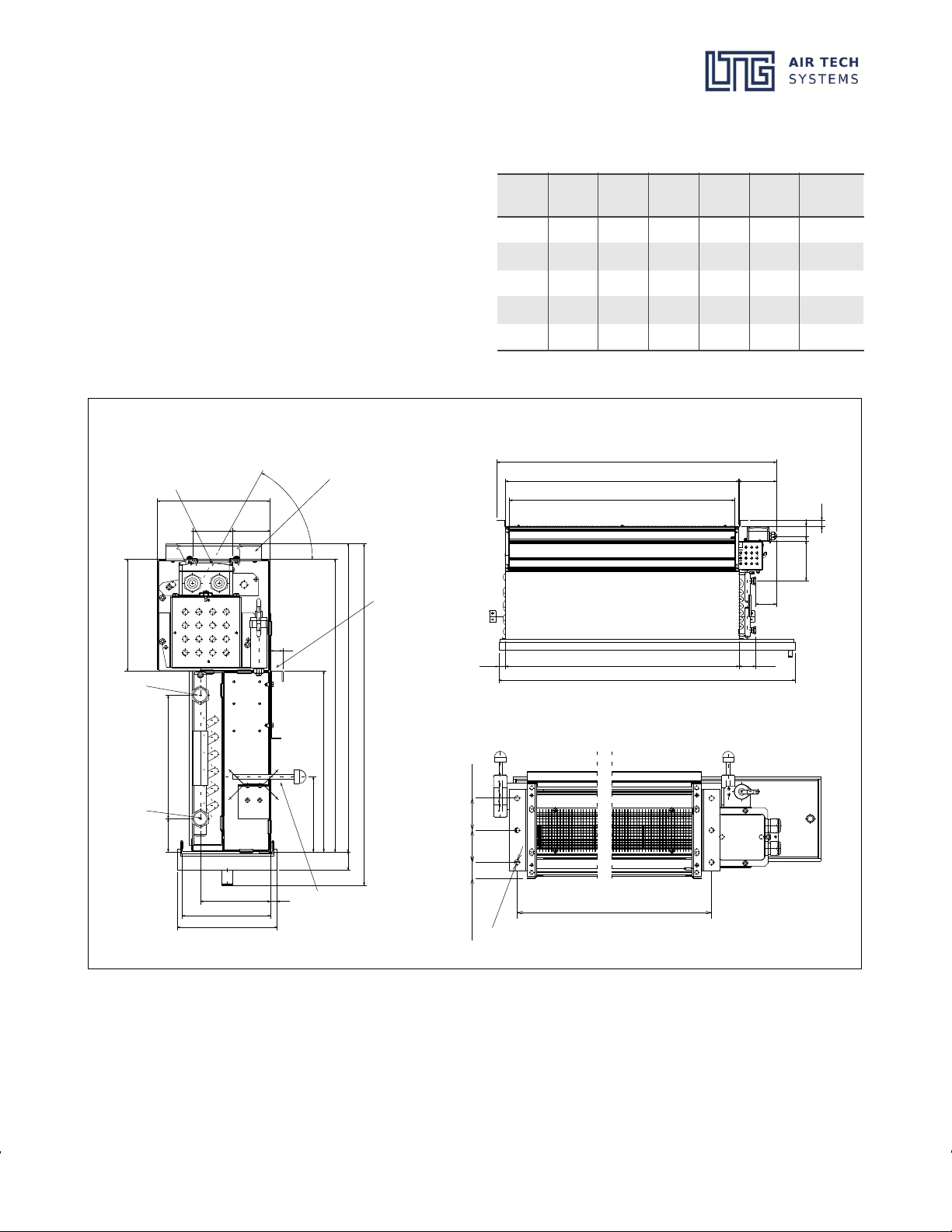
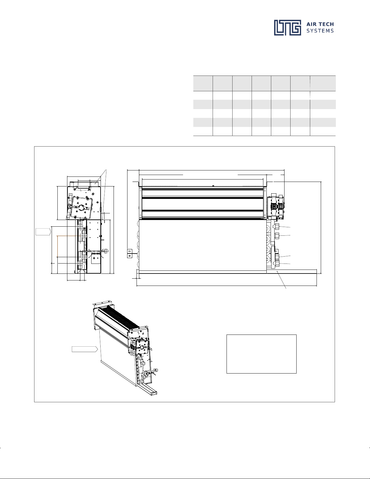
Fan coil units VFC, installation in sills
ELTG Incorporated ·PO Box 2889 ·Spartanburg, S.C. 29304, USA VFC_USA_BA (07/19)
Phone 864 599-6340, Fax -6344 ·e-mail: info@LTG-INC.net ·Internet: www.LTG-INC.net
Former editions are invalid ·Subject to technical modifications page 3 of 19
1. Safety
Assembly, dismantling and mainte
nance must be performed by trained
personnel in order to achieve reliability,
safety and best results.
1.1 Explanation of symbols and hints
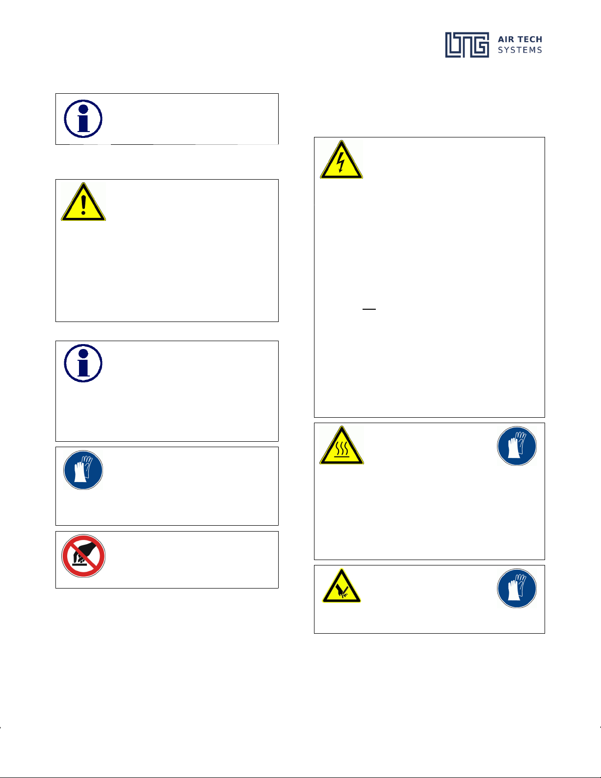
Operating safety symbol
This symbol is placed alongside every
operating safety instruction in these op
erating instructions, wherever there is a
danger to life and limb. Observe these
instructions and in such cases proceed
with extreme caution. Pass on all the op
erating safety instructions to other
users. In addition to the instructions
contained in these operating instruc
tions, the generally applicable safety
and accident prevention regulations
must be observed; as shown here, for
example: Warning of hazard point.
Information symbol
This information symbol is placed
alongside those points in the manual
which must be specifically observed in
order to ensure that the guidelines, reg
ulations, instructions and correct oper
ating sequences are observed and to
prevent damage to or destruction of the
unit and/or other components in the
system.
These mandatory symbols are linked to
the operating safety instructions and
show which protective measures must
be complied with at the appropriate
workstations and therefore specifically
mandate a certain action, as shown here
as an example: Wear protective gloves.
These prohibition symbols are linked to
the operating safety instructions ban
ning a dangerous or risky action, as
shownhereasanexample:Donot
touch.
1.2 Operating safety instructions
Carefully read the safety instructions before using any LTG
fan coil unit. Always follow the safety instructions!
The units meet any pertinent safety standards.
The installation and maintenance of air
conditioning units may be dangerous be
cause of high pressures and electrical com
ponents being alive. Therefore, the installa
tion, maintenance, and repair must be per
formed by qualified and trained staff only.
In particular electrical connections are to be provided,
removed, or modified by authorized persons only ob
serving all relevant safety instructions.
Safety instructions in the technical documentation and
on unit labels must be followed at all times.
Do not open theunit for cleaning,maintenance, orrepair
and do not remove covers and casings (air diffuser) un
less all conducting lines have been completely discon
nected. Do not connect or remove the plug-in connector
when under tension.
Any work regarding the electrical equipment is to be
performed by skilled and trained staff only. Connections
to the main power supply and the safety earth terminal
must be executed exactly as described in the wiring dia
gram.
Electrical operation of the unit in a partly disassembled
condition or of individual components is not permitted
since earth terminals might be interrupted.
During continuous opera
tion the motor may reach
temperatures of up to
149 °F. If necessary, allow
the motor to cool off or wear
gloves.
In the heating mode a water
temperature of up to 176 °F
may be achieved. Water-
carrying parts may be hot
so do not touch with your
bare hands to avoid burns.
Be careful when performing
work on the heat exchang
ers. Blades and housing
parts are sharp-edged.
Wear gloves during work
and handling.