LU-VE SAV8S User manual

31582873EN-03
2
LU-VE Exchangers is a trademark registered and owned by LU-VE Group.
LU-VE Exchangers reserves the right to change specifications without prior notification.
1 Important information
1.1 Disclaimer
This document applies to Spray Water Kit (KW) and charge/discharge module for
LU-VE Exchangers SAV/SAL, EAV/EAL, XAV/XAL, EHV/EHL, XHV/XHL units.
This document is supplied in combination with product manual and dedicated instruction manual.
The document must be carefully examined and instructions should be followed up at all times.
LU-VE Exchangers does not accept liability for any damage resulting from non-compliance to the
instructions as given in the manuals and order-related documents.
1.2 Warranty
This equipment is designed to operate properly when installed in accordance with accepted industry
standards. Failure to meet the following conditions may result in voiding the system warranty:
• Water circuit, nozzles or accessories must be installed following industry standards for good
piping practices.
• Set fluid flow and pressure of water circuit in accordance with what is described in this manual.
• Do not set the device to work over 12 bar.
• Use only water as described in this manual.
• Don’t use this kit for more than 150÷400 hours per year (according to the selected fin material).
• Don’t walk on pipes or supports.
• Factory installed layout must not be changed without written LU-VE Exchangers approval.
The connections require qualified installers to complete the liquids circuits.
Do not perform any installation or maintenance operations without having disconnected the power
supply.
2 Maintenance
Before winter or system shut-down periods, or when temperature could drop below +4 °C, make
sure that water inside the hydraulic circuit has been completely discharged to avoid damages.
KW shall not be used when there is a risk of icing. To check complete emptying:
• Ensure complete electrical isolation.
• Remove the pressure reducer. Be careful as water spillage might occur during this operation.
• Verify the absence of water inside collectors.
3 Components
3.1 Spray Water Kit
Quantity
Spray water pipe
1
each pipe consists of a number of modules
according to the length of the unit
Tube connector
female
1
per tube-end
Tube cap 1
per outlet

31582873EN-03
3
LU-VE Exchangers is a trademark registered and owned by LU-VE Group.
LU-VE Exchangers reserves the right to change specifications without prior notification.
Fixing material:
Quantity per fixing point
Pipe clamp FRS 1
Nut M8 3
Washer M8 3
Grower M8 2
Screw M8x25 2
Stirrup 1
Threaded bar
M8x100 1
3.2 Charge/discharge module (optional)
Quantity
charge/discharge
module
1
(pre-assembled)

31582873EN-03
4
LU-VE Exchangers is a trademark registered and owned by LU-VE Group.
LU-VE Exchangers reserves the right to change specifications without prior notification.
4 Installation
4.1 KW installation
Insert the female connectors on tube ends.
Place the end-cap on the tube outlet.
OUT
IN
KW components have to be connected to the
coil frame.
Fix the stirrups to the coil frame by tightening the
M8 screws, growers, wahshers and nuts.
coil frame
Assemble the pipe clamps FRS and fix them to
the stirrups.

31582873EN-03
5
LU-VE Exchangers is a trademark registered and owned by LU-VE Group.
LU-VE Exchangers reserves the right to change specifications without prior notification.
Insert the pipe into the clamps and tighten the M8 nuts in such a way that the pipe is sloping of
about 1% between the inlet and outlet.
Slope is driven by the height of threaded bar in the horizontal installation and by the position in the
stirrup loop in the vertical installation.
With KW only, lower position shall be opposite to the water inlet to facilitate the water discharge.
horizontal installation
vertical installation
IN
OUT
IN
OUT

31582873EN-03
6
LU-VE Exchangers is a trademark registered and owned by LU-VE Group.
LU-VE Exchangers reserves the right to change specifications without prior notification.
horizontal installation
+ charge/discharge module
With the charge/discharge module to be installed, water inlet is at lower position.
vertical installation
+ charge/discharge module
Position the pipe in such a way that the nozzle
angle is set on 30° on horizontal.
Lock the clamps.
30°
IN
OUT
IN
OUT

31582873EN-03
7
LU-VE Exchangers is a trademark registered and owned by LU-VE Group.
LU-VE Exchangers reserves the right to change specifications without prior notification.
IN
4.2 Charge/discharge module installation (optional)
The charge/discharge module is optional and can’t be used if the KW is not installed.
The module is pre-assembled.
Tighten the charge/discharge module on the KW
inlet.
5 Operation
5.1 Pipeline connections
Each pipeline is equipped with 1/2" threaded female GAS junctions for the water feed.
5.2 KW association
LU-VE Exchangers provides different types of kit according to the unit model and the number of
fans.
Model Single fan row
1 fan 2 fans 3 fans 4 fans 5 fans 6 fans
SAV8S 10242600 10242602 10242604 10242606 10242608 /
SAV8T 10242600 10242602 10242604 10242606 10242608 /
EAV8S 10242624 10242626 10242628 10242630 10242632 10242634
EAV8T 10242624 10242626 10242628 10242630 10242632 10242634
EHV90F 10242625 10242627 10242629 10242631 10242633 10242635
EAV9N 10242625 10242627 10242629 10242631 10242633 10242635
EAV9U 10242624 10242626 10242628 10242630 10242632 10242634
EAV9X 10242624 10242626 10242628 10242630 10242632 10242634
EHV95F 10242625 10242627 10242629 10242631 10242633 10242635
EHV95N 10242625 10242627 10242629 10242631 10242633 10242635
EHV95U 10242624 10242626 10242628 10242630 10242632 10242634
EHV95X 10242624 10242626 10242628 10242630 10242632 10242634
XAV9K 10242625 10242627 10242629 10242631 10242633 10242635
XAV9N 10242625 10242627 10242629 10242631 10242633 10242635
XAV9U 10242624 10242626 10242628 10242630 10242632 10242634
XAV9X 10242624 10242626 10242628 10242630 10242632 10242634
XHV95F 10242625 10242627 10242629 10242631 10242633 10242635
XHV95N 10242625 10242627 10242629 10242631 10242633 10242635
XHV95U 10242624 10242626 10242628 10242630 10242632 10242634
XHV95X 10242624 10242626 10242628 10242630 10242632 10242634
XAV10N 10242625 10242627 10242629 10242631 10242633 10242635

31582873EN-03
8
LU-VE Exchangers is a trademark registered and owned by LU-VE Group.
LU-VE Exchangers reserves the right to change specifications without prior notification.
Model Dual fan row
4 fans 6 fans 8 fans 10 fans 12 fans 14 fans 16 fans
SAV8S 10242610 10242612 10242614 10242616 10242618 10242620 10242622
SAV8T 10242610 10242612 10242614 10242616 10242618 10242620 10242622
EAV8S 10242636 10242638 10242640 10242642 10242644 / /
EAV8T 10242636 10242638 10242640 10242642 10242644 / /
EHV90F 10242637 10242639 10242641 10242643 10242645
EAV9N 10242637 10242639 10242641 10242643 10242645
EAV9U 10242636 10242638 10242640 10242642 10242644 / /
EAV9X 10242636 10242638 10242640 10242642 10242644 / /
EHV95F 10242637 10242639 10242641 10242643 10242645
EHV95N 10242637 10242639 10242641 10242643 10242645
EHV95U 10242636 10242638 10242640 10242642 10242644 / /
EHV95X 10242636 10242638 10242640 10242642 10242644 / /
XAV9K 10242637 10242639 10242641 10242643 10242645
XAV9N 10242637 10242639 10242641 10242643 10242645
XAV9U 10242636 10242638 10242640 10242642 10242644 / /
XAV9X 10242636 10242638 10242640 10242642 10242644 / /
XHV95F 10242637 10242639 10242641 10242643 10242645
XHV95N 10242637 10242639 10242641 10242643 10242645
XHV95U 10242636 10242638 10242640 10242642 10242644 / /
XHV95X 10242636 10242638 10242640 10242642 10242644 / /
XAV10N 10242637 10242639 10242641 10242643 10242645
Model Charge/discharge module
SAV8S 10241678
SAV8T 10241678
EAV8S 10241678
EAV8T 10241678
EHV90F 10241678
EAV9N 10241678
EAV9U 10241678
EAV9X 10241678
EHV95F 10241678
EHV95N 10241678
EHV95U 10241678
EHV95X 10241678
XAV9K 10241678
XAV9N 10241678
XAV9U 10241678
XAV9X 10241678
XHV95F 10241678
XHV95N 10241678
XHV95U 10241678
XHV95X 10241678
XAV10N 10241678

31582873EN-03
9
LU-VE Exchangers is a trademark registered and owned by LU-VE Group.
LU-VE Exchangers reserves the right to change specifications without prior notification.
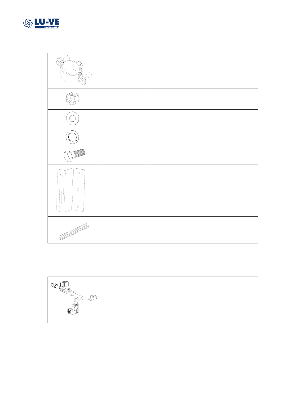
5.3 Nozzle type and quantity
LU-VE provides different types of nozzle according to the unit model.
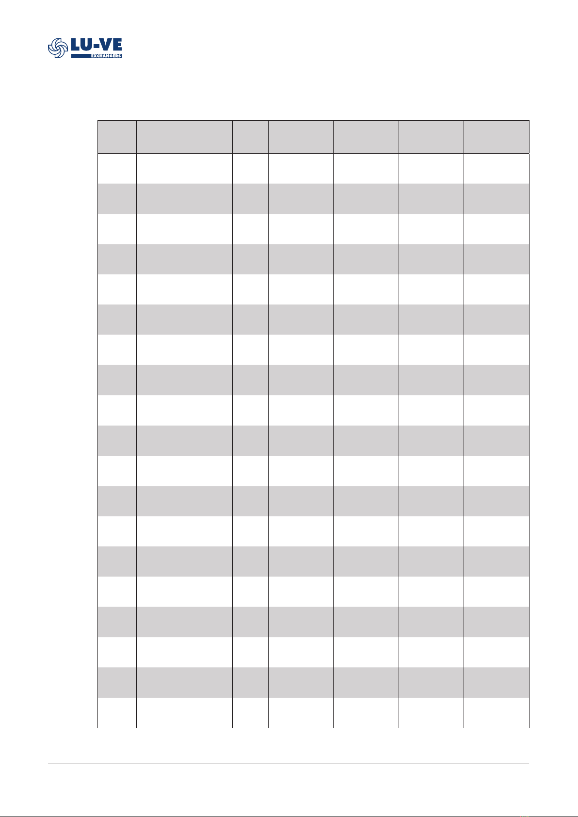
Item
code
Item
description
Nozzle
type
Nozzle quantity
per fan
Nominal flow rate
per nozzle*
Nozzle quantity
total
Nominal flow rate
total*
10242600 Spray water
tube_45T_1600_1M_Type I TYPE I 2 30,6 2 61
10242602 Spray water
tube_45T_1600_2M_Type I TYPE I 2 30,6 4 122
10242604 Spray water
tube_45T_1600_3M_Type I TYPE I 2 30,6 6 184
10242606 Spray water
tube_45T_1600_4M_Type I TYPE I 2 30,6 8 245
10242608 Spray water
tube_45T_1600_5M_Type I TYPE I 2 30,6 10 306
10242610 Spray water
tube_89T_1600_2M_Type I TYPE I 2 30,6 8 245
10242612 Spray water
tube_89T_1600_3M_Type I TYPE I 2 30,6 12 367
10242614 Spray water
tube_89T_1600_4M_Type I TYPE I 2 30,6 16 490
10242616 Spray water
tube_89T_1600_5M_Type I TYPE I 2 30,6 20 612
10242618 Spray water
tube_89T_1600_6M_Type I TYPE I 2 30,6 24 734
10242620 Spray water
tube_89T_1600_7M_Type I TYPE I 2 30,6 28 857
10242622 Spray water
tube_89T_1600_8M_Type I TYPE I 2 30,6 32 979
10242624 Spray water tube_45-
54T_2133_1M_Type I TYPE I 2 30,6 2 61
10242625 Spray water tube_45-
54T_2133_1M_Type III TYPE III 2 69,6 2 139
10242626 Spray water tube_45-
54T_2133_2M_Type I TYPE I 2 30,6 4 122
10242627 Spray water tube_45-
54T_2133_2M_Type III TYPE III 2 69,6 4 278
10242628 Spray water tube_45-
54T_2133_3M_Type I TYPE I 2 30,6 6 184
10242629 Spray water tube_45-
54T_2133_3M_Type III TYPE III 2 69,6 6 418
10242630 Spray water tube_45-
54T_2133_4M_Type I TYPE I 2 30,6 8 245

31582873EN-03
10
LU-VE Exchangers is a trademark registered and owned by LU-VE Group.
LU-VE Exchangers reserves the right to change specifications without prior notification.
Item
code
Item
description
Nozzle
type
Nozzle quantity
per fan
Nominal flow rate
per nozzle*
Nozzle quantity
total
Nominal flow rate
total*
10242631 Spray water tube_45-
54T_2133_4M_Type III TYPE III 2 69,6 8 557
10242632 Spray water tube_45-
54T_2133_5M_Type I TYPE I 2 30,6 10 306
10242633 Spray water tube_45-
54T_2133_5M_Type III TYPE III 2 69,6 10 696
10242634 Spray water tube_45-
54T_2133_6M_Type I TYPE I 2 30,6 12 367
10242635 Spray water tube_45-
54T_2133_6M_Type III TYPE III 2 69,6 12 835
10242636 Spray water tube_89-
107T_2133_2M_Type I TYPE I 2 30,6 8 245
10242637 Spray water tube_89-
107T_2133_2M_Type III TYPE III 2 69,6 8 557
10242638 Spray water tube_89-
107T_2133_3M_Type I TYPE I 2 30,6 12 367
10242639 Spray water tube_89-
107T_2133_3M_Type III TYPE III 2 69,6 12 835
10242640 Spray water tube_89-
107T_2133_4M_Type I TYPE I 2 30,6 16 490
10242641 Spray water tube_89-
107T_2133_4M_Type III TYPE III 2 69,6 16 1114
10242642 Spray water tube_89-
107T_2133_5M_Type I TYPE I 2 30,6 20 612
10242643 Spray water tube_89-
107T_2133_5M_Type III TYPE III 2 69,6 20 1392
10242644 Spray water tube_89-
107T_2133_6M_Type I TYPE I 2 30,6 24 734
10242645 Spray water tube_89-
107T_2133_6M_Type III TYPE III 2 69,6 24 1670
* 3 bar [L/H]
This manual suits for next models
20
Table of contents