Lucas Led 200W User manual

-1-
USER MANUAL
ITEM No.:200W/230W

-2-
Please read over this Manual before Operating the Light Fixture
First, thank you for purchasing our professional lighting equipments.
This manual includes important information of how to install and use the fixture safely. Please
install and operate it correctly as required, and keep the manual properly in case of need.
This moving head light is the perfect combination of humanity and industrial design with
beautiful modeling. The body of the light is made of aluminum alloy and high temperature
resistant engineering plastic materials with wonderful cooling effect. And the transmission
mechanism adopts electronic positioning technology. This product fully meets the CE standard
which employs the international standard signal control DMX512, and is widely used in TV station,
disco, dance hall, night club and other indoor or outdoor shows.
This product is in good condition and packed well before shipping. Please follow strictly the stated
warning and instructions when operating. It is not guaranteed by our company for any damage or
breakdown of the product caused by misuse the product before reading the operation manual.
Warnings:
Please check if there is any transportation damage before using. And if there is any damage, please
stop using it, and contact the distributor or manufacturer as soon as possible. Please keep it away
from Combustible materials, and unlock the X-, Y-axis before using. The fixture should be installed in places
with good ventilation, keep it away from the wall at least 10cm above, and then check if the fans are in good
conditions.
Please don’t project the light beam on the combustible directly, and keep the fixture at least 12m away from the
projection objects.
Please don’t look directly into the light source lest any damage to your eyes. And please make sure the using
power voltage is in accordance with the stated voltages before using.
Attention: Please power off before installing, repairing or cleaning the fixture.
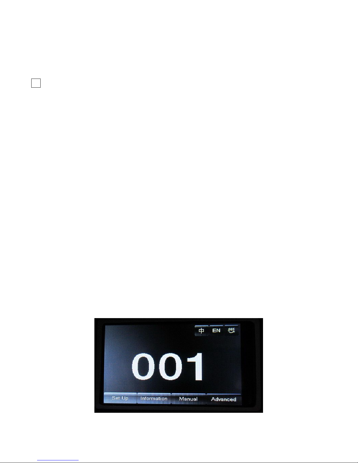
1. Operation Modes:
Touch Turning Wheel Function
“Up”button Turn left Select、Edit
“Down”button Turn right Select、Edit
“Confirm”button(“OK”)
Press the wheel Start running
Start editing、Stop editing
“Return”button Press the wheel under Return
manual
Return to previous page

-3-
For example, how to change DMX address?
1. Please press “Setting” in the main interface to enter “setting” interface.
2. There are 4 touch key-presses on the right side, namely, “Up” “Confirm” “Down” “Return” buttons.
3. Please press “Up” or “Down” keys to enter “DMX address”.
4. Please press “Confirm” to edit.
5. Please press “Up” or “Down” keys to change DMX address (the new DMX address would be saved
automatically and start to run)
6. Please press “Confirm” to exit editing.
7. Please press “Return” to exit main manual.
Operation modes for turning wheel:
1. Please press “Setting” button under the main interface, and turn the wheel.
2. Please press the wheel to enter “setting” interface.
3. Please turn the wheel to enter “DMX address” interface under “setting” interface.
4. Please press the wheel to edit.
5. Please turn the wheel to change the DMX address.
6. Please press the wheel to exit editing after the modification.
7. Please turn the wheel to enter “Return”, and then press the wheel to return the main interface.
2. Control Panel Instructions:
2.1. Main Interface

-4-
The 3 buttons on the up right corner are for language switch and screen rotation.
The 4 buttons on the bottom are for sub-interfaces.
How to use the wheel to control the sub-interface? Please see as follows::
For “Up” button: Please turn left.
For “Down” button: Please turn right.
For “Confirm” button: Please press the wheel.
Operation of Dialog by turning wheel:
If for “YES”, then press the wheel. And if for “No”, then turn the wheel.
2.2. Setting of Interface
Options Instructions
Running Mode DMX
Slave machines:accept DMX signals from controller or Master machine.
Auto
Master-Slave :running automatically, and send DMX signals to slave
machines.
Attention :If need to check the light effects, please power on the lamp
first to enter self-propelled state.
DMX Address 1-512 Press “Confirm” button to edit. First is for “hundred's digit”, and press
“Up” and “Down” to change the address codes. Press “Confirm” button
the second time to edit “ten's digit”, and press again the “Confirm”
button to edit “unit's digit”. Please press it again to exit editing.
Channels 16 17-20 CH Invalid
20 17-20CH to control speed(please refer to Channel chart)
X Reverse off
on
Y Reverse off
on

-5-
XY Exchange off
on Exchanging XY channels(Pan/Tilt fine included)
XY Encorder on Use Encorder (optocoupler) to judge out of sync or not, and self-correct
the position.
off Don’t use Encorder (optocoupler) to rectify the position
No DMX signal stay Stay the same
reset Stop running
Screen Save mode on Screen light off automatically after 30secs
off Screen stay on
Starting up off
Reset directly when power on,lamp stay off(need to operate the manu or
console to light up the lamp)
on Lamp on when power on,and reset after the lamp is fully lighted up.
Recover default setting Press “Confirm” button to see the confirm dialog, and press “Confirm”
button again to recover default setting.
2.3.Information Interface
Options Illustrate
Software
version
The current software version
Total time Total time (accurate to the minute)
The use of time Since the boot (accurate to the minute)
DMX Channel Click here to go to the sub-interface, numerical and percentage display channel for viewing.
System error
records
If the red ERR indicator light, illustrate lamps run error, Details Click here go to the
sub-interface view. After you finish, press "OK" key to delete error records.
Note: sometimes it is not Hall or optocoupler installation problems, but the motor line
reversed.
2.4. Manual Control Interface
This interface is used to control the current lighting, neither belong to slave state (does not receive DMX signal),
nor belong to the host state (do not send DMX signal)
Options Illustrate
Reset Press the OK button after see a confirmation dialog box, click "OK" key to enter the
reset interface, all motor reset again.
Color Wheel 0-255 Press “Confirm” button to edit. First is for “hundred's digit”, and press “Up” and
“Down” to change the address codes. Press “Confirm” button the second time to edit
“ten's digit”, and press again the “Confirm” button to edit “unit's digit”. Please
press it again to exit editing.
。。。。。。 0-255
Gobo Wheel
Speed
0-255
Bulb Control Turn on
Turn
off

-6-
2.5. Advanced Interface
The code is “up down up down”,and code for the wheel is “ left right left right”.
Manu Operation modes:Press “Up” to see the first “*”,and press “Down” key to see the second “*”,and press
“Up” to see the third “*”,and press “Down” key to see the fourth “*”,and last press “Confirm” key to enter
password confirmation.
Turning wheel Operation modes:Turn one bit left to see first “*”, and Turn one bit right to see the second “*”,
and turn one bit left to see the third “*”, and Turn one bit right to see the fourth “*”,and last press the wheel
to enter password confirmation.
Options Instructions
Touch Screen Calibration Please touch the place according to the prompt of the cross cursor in the
Calibration interface. If the 4 values received the right data, then save the data. If
failed, it will keep repeating. Please press “Confirm” button to stop Calibration
any time.
Reset Calibration When enter sub-menu, the reset location of X.Y axis motors is adjustable. It is not
able to edit “unit’s digit”, “ten's digit” or “hundred's digit” or long-time press
for Reset Calibration which needs to be calibrated step by step, which is different
from address code and channel values.
Attention:Please don’t conduct Reset Calibration, when the motors are working.
And please reset the fixture before Reset Calibration when necessary.
CHANNEL CHANNEL MODE
16 20
1 COLOUR WHEEL COLOUR WHEEL
2 STOP/STROBE STOP/STROBE
3 DIMMER DIMMER
4 STATIC GOBO CHANGE STATIC GOBO CHANGE
5 PRISM ROTATION PRISM ROTATION
6 PRISM ROTATION PRISM ROTATION
7 EFFECTS MOVEMENT(UNUSED) EFFECTS MOVEMENT(UNUSED)
8 FROST FROST
9 FOCUS FOCUS
10 PAN PAN
11 PAN FINE PAN FINE
12 TILT TILT
13 TILT FINE TILT FINE
14 FUNCTION(UNUSED) FUNCTTON(UNUSED)

-7-
15 RESET RESET
16 LAMP CONTROL LAMP CONTROL
17 PAN-TILT TIME
18 COLOUR TIME
19 DIMMER-PRISM-FROST TIME
20 GOBO TIME
COLOER WHEEL-channel 1
BIT EFFECT 备注
255 FAST ROTATION
...... ……
150 SLOW ROTATION
145 COOL COLOR +WHITE In order to facilitate memory,
color value is always a
multiple of five. Color ratio
can be adjusted, for example:
when the value is five, so it
should be 50% white, dark red
50%, if the value is 4, so it
should be 60% white, dark red
40%: If the value is six, so it
should white 40% dark, red
60%.
140 COOL COLOR
135 BROWNISH YELLOW+COOL COLOR
130 BROWNISH YELLOW
125 LIGHT BLUE-PURPK+BROWNISH YELLOW
120 LIGHT BLUE-PURPK
115 MAGENTA+LIGHT BLUE-PURPK
110 MAGENTA
105 YELLOW GREEN+MAGENTA
100 YELLOW GREEN
95 LIGHT YELLOW+YELLOW GREEN
90 LIGHT YELLOW

-8-
85 BLUISH GREEN+LIGHT YELLOW
80 BLUISH GREEN
75 PURPLISH RED+BLUISH GREEN
70 PURPLISH RED
65 FLUORESCENCE+PURPLISH RED
60 FLUORESCENCE
55 BROWN+FLUORESCENCE
50 BROWN
45 GREEN+BROWN
40 GREEN
35 BLUE+GREEN
30 BLUE
25 DARK YELLOW +BLUE
20 DARK YELLOW
15 RED+DARK YELLOW
10 RED
5 WEITE+RED
0 WEITE
STOP/STOBE-channel 2
BIT EFFECT Remarks
252-255 OPEN Controlled by a dimmer channel
239-251 RANDOM FAST STROBE
226-238 RANDOM MEDIUM STROBE
213-225 RANDOM SLOW STROBE
208-212 OPEN Controlled by a dimmer channel
207 FAST PULSATION
…… ……
108 SLOW PULSATION
104-107 OPEN Controlled by a dimmer channel
103 FAST STROBE
…… ……
4 SLOW STROBE
0-3 CLOSED
DIMMER-channel 3
BIT EFFECT Remarks
255 100%

-9-
…… ……
0 0%
STATIC GOBO CHANGE-channel 4
BIT EFFECT Remarks
255 GOBOI 17 SHAKE,FAST SPEED Every five values is correspond to a pattern.
…… ……
251 GOBO 17 SHAKE,SLOW SPEED
250 GOBO 16 SHAKE,FAST SPEED
…… ……
246 GOBO 16 SHAKE,SLOW SPEED
…… ……
180 GOBO 2 SHAKE,FAST SPEED
…… ……
176 GOBO 2 SHAKE,SLOW SPEED
175 GOBO 1 SHAKE,FAST SPEED
…… ……
171 GOBO 1SHAKE,SLOW SPEED
170 FAST ROTATION
…… ……
135 SLOW ROTATION
130-134 STOP
129 SLOW ROTATION
…… ……
90 FAST ROTATION

-10 -
85 GOBO 17 Value is always five multiple
80 GOBO 16
75 GOBO 15
70 GOBO 14
65 GOBO 13
60 GOBO 12
55 GOBO 11
50 GOBO 10
45 GOBO 9
40 GOBO 8
35 GOBO 7
30 GOBO 6
25 GOBO 5
20 GOBO 4
15 GOBO 3
10 GOBO 2
5 GOBO 1
0 WHITE
PRISM INSERTION-channel 5
BIT EFFECT Remarks
128-255 PRISM INSERTED
0-127 PRISM EXCLUDED
PRISM ROTATION-channel 6
BIT EFFECT Remarks
255 FAST ROTATION
…… ……
193 SLOW ROTATION
191-192 STOP
190 SLOW ROTATION
…… ……
128 FAST ROTATION
0-127 POSITION
EFFECTS MOVEMENT channel 7(NOUSED)
FROST-channel 8
BIT EFFECT Remarks
128-255 FROST INSERTED
0-127 FROST EXCLUDED

-11 -
FOCUS-channel 9
BIT EFFECT Remarks
255 100%
…… ……
0 0%
PAN-channel 10
(………)
PAN FINE-channel 11
(………)
TILI-channel 12
(………)
TILT FINE-channel 13
(………)
FUNCTION-channel 14(NOUSED)
RESET-channel 15
BIT EFFECT Remarks
128-255 COMPLETE RESET Reset is activated passing through the unused range and
staying 5 seconds.
77-127 PAN/TILT RESET
26-76 EFFECTS RESET
0-25 UNUSED RANGE
LAMP CONTROL-channel 16
BIT EFFECT Remarks
128-255 LAMP ON Lamp switch passing through the unused range and staying 5 seconds.
10-100 LAMP OFF

-12 -
0-9 UNUSED RANGE
TIMING CHANNELS
Timing Channel Channel function Remark
17 Pan-Tilt time Pan-Tilt-(Pan fine-Tilt fine) 255 SLOW SPEED
….. ……
0 FAST SPEED
18 Color time Color wheel
19 Beam time Dimmer-Prism-Frost
20 Gobo time Static Gobo
Control signal connection
XLR-XLR control cable from the DMX output of the controller connected to each projector DMX input port,
and from the first fixture in the DMX output port connected to the second fixture in the DMX input port, and so
on, until the All lighting connection is completed, and then plug the supplied loop connected to the signal output
of the last fixture to complete the connection, as shown:
Note: Keep in mind that in the last fixture's output circuit connected to a plug, this circuit is connected to a 120
ohm resistor inserted between the CANON (XLR) plug 2 feet and 3 feet, this loopinterpolation can effectively
avoid the reflection signal generated by DMX512 signal in transfer input process.
The moving head light utilization the 3-pin XLR socket (head),if you are using the controller uses a 5-pin XLR
socket (head), you must use a 5-pin to 3-pin converter cable, as shown below:
3-pin and 5-pin control cable plug (male and female) connector.

-13 -
Three pin(Canon)DMX512 connector

-14 -
Installation

-15 -

-16 -

-17 -

-18 -

-19 -

-20 -
This manual suits for next models
1
Table of contents
Other Lucas Led Dj Equipment manuals
Popular Dj Equipment manuals by other brands

STUDIODUE
STUDIODUE ARCHIBAR-SL100 RGBW/FC user manual

FOS Technologies
FOS Technologies 150W LED Spot user manual

afx light
afx light BEAM2R-X user manual

FOS Technologies
FOS Technologies PAR COB 200W LED TW user manual

Expolite
Expolite TourBar 12 Pix WW user manual

Sound Sation
Sound Sation BAR-18-12W-IP65 user manual