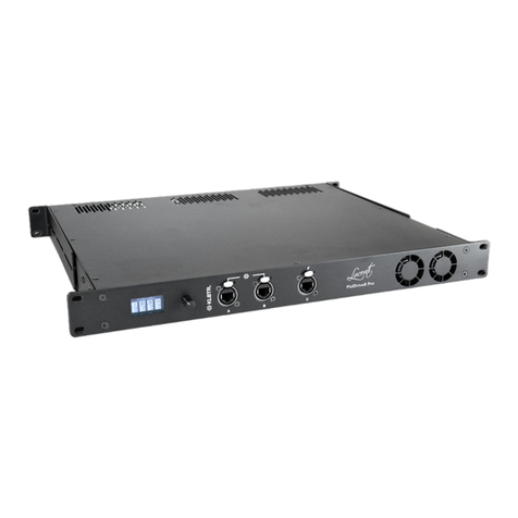
Lucenti BLACKWAVE PIXLDRIVE1 User manual

1
EN
BLACKWAVE
PIXLDRIVE1 CONTROLLER
USER MANUAL

2
BLACKWAVE PIXLDRIVE1 CONTROLLER
USER MANUAL
Worldwide distribution by FACE BVBA Belgium
HOEK 76 UNIT 301 – 2850 BOOM – BELGIUM
PHONE: +32 3 844 67 97
Subject to modications.
Issue date: 2020-01
Version: 1.00
All trademarks referenced are trademarks or registered trademarks
of their respective owners, whose protected rights are acknowledged.
This manual was produced with care. However, no rights can be derived.
Lucenti cannot accept liability for any errors in this manual or their consequences.
Copyright Lucenti

TABLE OF CONTENTS
4
1 YOUR BLACKWAVE COLLECTION PIXLDRIVE1 CONTROLLER 6
2 THE BLACKWAVE COLLECTION TECHNOLOGY 7
3 SAFETY INSTRUCTIONS & WARRANTY 8
3.1 SIGNS AND SYMBOLS USED 8
3.2 USAGE INTRUCTIONS 8
3.3 WARRANTY 9
4 UNBOXING 10
5 TERMS & CONCEPTS 11
6 CABLING & POWERING UP 12
6.1 CONNECTING BLACKWAVE PIXEL BARS 12
6.2 MAXIMUM CABLING CONSIDERATIONS 13
7 QUICK START GUIDE 15
7.1 CONNECT TO CONTROLLER 15
7.1.1 ETHERNET 16
7.1.2 IN WI-FI AD-HOC MODE 17
7.1.3 IN WI-FI INFRASTRUCTURE MODE 17
7.2 PERFORM AUTO-SETUP 18
7.3 CHOOSING THE RIGHT DEVICE OPERATION MODE 20
7.3.1 ART-NET 20
7.3.2 SACN (E.131) 21
7.3.3 STANDALONE FX 21
7.3.4 CHANGING THE DEVICE OPERATION MODE 21
8 USING THE BUILT-IN LCD AND BUTTONS 23
8.1 OVERVIEW 23
8.2 MENU FLOW-CHART 25
9 USING THE BUILT-IN WEB INTERFACE 26
9.1 DASHBOARD 27
9.1.1 SYSTEM SETTINGS 28
9.1.2 DMX PIXEL MAPPING 29
9.2 NETWORK 31
9.2.1 ETHERNET 32
9.2.2 WI-FI 32

6
YOUR BLACKWAVE COLLECTION PIXLDRIVE1
CONTROLLER
YOUR BLACKWAVE COLLECTION PIXLDRIVE1 CONTROLLER
1
Thank you for purchasing a Lucenti BlackWave Collection PixlDrive1 controller!
The BlackWave Collection pixel system consists of ultra-light, slim, weatherproof RGBW pixel xtures
such as led pixel bars and an easy-to-use controller. These pixel bars contain individually controllable
LEDs, can be daisy chained up to 400 pixels and have a variety of interchangeable lters. The controller
can receive DMX512 packets through dierent Ethernet protocols, supporting Art-Net I (broadcast),
Art-Net II, 3 & 4 unicast, sACN/E1.31 Multicast and sACN Unicast. It also houses a customizable internal
eect engine.
The controller is equipped with dual etherCON network ports connected to a built-in 100Mbit network
switch. The controller also contains a Wi-Fi radio allowing it to connect to external Wi-Fi networks or
to create its own.
There are two ways to operate the controller and change settings:
1. Via the built-in website through Ethernet or Wi-Fi, signaled by the icon
2. Via the built-in LCD display and button, signaled by the icon

7
THE BLACKWAVE COLLECTION
TECHNOLOGY
THE BLACKWAVE COLLECTION TECHNOLOGY
2
The BlackWave controller and pixel products are developed and engineered from the ground up and
communicate through a custom digital bus protocol, called ‘PixlBus’. The ‘PixlBus’ protocol allows
devices to communicate bi-directionally at high speeds. This enables the controller to send colors
to each pixel xture individually but also to read status or product information from each device.
Using the ‘PixlBus’ protocol, the BlackWave Collection technology can enumerate, address and map
all connected devices in an automated way. As a result, the system can be easily setup through one
button click; dramatically decreasing build-up time.
The ‘PixlBus’ protocol synchronizes all connected pixel xtures to gain an optimally smooth visual
performance.
The electrical bus system that transports the ‘PixlBus’ protocol uses dierential wiring resulting in
increased cable lengths and better signal quality.

8
SAFETY INSTRUCTIONS & WARRANTY
3
3.1 Signs and symbols used
Sign/symbol Description
Indicates side information about the current subject.
Indicates an important warning that needs to be read in order to be able
to continue.
CAUTION: TO REDUCE THE RISK OF ELECTRIC SHOCK, DO NOT REMOVE THE COVER. THE DEVICE HAS
NO USER SERVICEABLE PARTS INSIDE. REFER FOR SERVICING TO QUALIFIED SERVICE PERSONNEL
ONLY.
Read Instructions - All the safety and operating instructions should be read before the device is
operated.
Cleaning - Do not use cleaning solvents or abrasives for cleaning. Use a soft cloth to wipe the outer
surface of the device.
Heat - The device should be situated away from heat sources such as radiators or heating systems.
Power Source - The device should be connected to a power supply complying to the requirements as
documented in the technical specications section of this document.
Servicing - The user should not attempt to service the device. All servicing should be referred to
qualied service personnel. Risk of electrical shock exists when opening the device.
Damage Requiring Service - The appliance should be serviced by qualied service
personnel when:
• The power cords on the power inlet or output have been damaged
• Liquid has been spilled into the device
• The device does not appear to operate normally
3.2 Usage instructions

9SAFETY INSTRUCTIONS & WARRANTY
Warranty Period - 2 (two) years
This warranty can be provided when the Lucenti products were used in their normal intended use and
when due care and compliance with the instructions given by Lucenti was observed. The obligations
of Lucenti have been restricted to these warranty terms and conditions and the warranty does not
cover losses incurred as a result of damage to other property or persons.
The warranty does not cover defects which are the result of:
• transportation of the Lucenti product
• negligence by the user of the Lucenti product or failure to observe the instructions given by
Lucenti or proper care
• circumstances outside the control of Lucenti, such as theft, accidents or acts of vandalism
• failure to observe the installation or operating instructions, or other failures, when installing the
Lucenti product
• normal wear and tear
In no event shall the warranty period for any Lucenti products including repaired or replaced parts,
extend beyond the original warranty period stated above.
The customer is responsible for the costs and related taxes and duties for shipping of defected
products for repair or replacement.
Repair onsite is not covered.
Procedure in case of a defect
Check our website http://lucenti.lighting or contact our support team for more information on how
to return a defective Lucenti product.
Temperature - The equipment shall be used at a maximum ambient temperature of 45° C / 113° F.
Regular inspection of the products and the mounting is necessary to ensure safety. In case of doubt
about the safety of the product and the installation, the customer should immediately contact Lucenti.
3.3 Warranty

10
UNBOXING
UNBOXING
4
The PixlDrive1 controller provides both data and power to the connected xtures through the
PixlBus connector.
The specics of the controller are described in gure 2 and 3. The dierent components are
explained in the following table.
Figure 3: Back of PixlDrive1 controller
PixlDrive1
Controller
The PixlDrive1 Controller is the heart of the system. The controller
translates incoming Art-Net or sACN/E1.31 to the proprietary ‘PixlBus’
output. It also features a powerful internal eect engine which allows
for creating rich and dynamic light eects on the connected xtures.
LCD Display This LCD screen is used to display a menu to the user. The menu and its
items can be controlled through the rotary pushbutton.
Rotary pushbutton This button controls the built-in LCD display.
Network The controller is equipped with dual Ethernet etherCON network ports
and an internal 100Mbit network switch. This allows to daisy-chain
multiple controllers together.
PixlBus The PixlBus provides power and data to all connected xtures.
Power in This cable end (powerCON TRUE1) will be connected to an open power
outlet. This outlet will provide power to the controller AND all connected
xtures through the internal power supply and PixlBus output.
Power out The power can be daisy-chained between multiple controllers using
interlinking powerCON TRUE1 cables.
Figure 2: Front of PixlDrive1 controller
LCD Display Rotary pushbutton

11TERMS & CONCEPTS
TERMS & CONCEPTS 5
Ethernet
connectivity
The controller has a built-in 100Mbit network switch exposed through
two etherCON ports. These ports can receive Art-Net or sACN/E1.31
data and are also used to reach the built-in conguration webpage.
Wi-Fi connectivity The controller is equipped with a built-in Wi-Fi radio. This radio can be
congured in two modes:
• Infrastructure Mode: connect the controller to an existing external
Wi-Fi network
• Ad-hoc Mode: the controller will create its own Wi-Fi network. No
external networking hardware is required.
Wi-Fi can only be used to reach the built-in conguration web page and
NOT to receive Art-Net or sACN/E1.31 data.
PixlBus protocol The controller communicates with each of the connected xtures
through a proprietary protocol called ‘PixlBus’. This high-speed
communication protocol allows for sending pixel data at high
framerates but also to request product and status information from
each of the connected xtures. It also allows to perform a rmware
update of a xture, even when multiple xtures are connected.
Ethernet DMX
input
The controller can receive DMX512 packets through the following
Ethernet DMX protocols: Art-Net I (broadcast), Art-Net II, 3 & 4 unicast,
sACN/E1.31 Multicast and sACN Unicast.
Standalone eect
engine
The controller has a powerful built-in eect engine that can display
colorful animations on the connected xtures. This engine is standalone,
it will loop and keep playing eects until it is instructed otherwise.
Auto Setup The ‘PixlBus’ technology allows to enumerate, address and map all
connected devices in an automated way. As a result, the system can be
easily setup through one button click; dramatically decreasing build-up
time.
Pixel Mapping Performing an auto setup will automatically map all xtures according
to the chosen parameters. The DMX mapping for each xture can then
easily be consulted through the built-in conguration webpage.
Please carefully read the following section to understand the terminology
user later on in this manual.

12 CABLING & POWERING UP
CABLING & POWERING UP6
A PixlDrive1 controller sits between a power outlet and a collection of xtures that understand the
‘PixlBus’ protocol. The PixlBus provides power and data to all connected xtures. The following gures
focus on connecting BlackWave Collection BW-100 and BW-50 pixel bars to the controller.
6.1 Connecting BlackWave pixel bars
It is advised against connecting non-Pixlbus devices to the
controller
BlackWave pixel xtures display their PixlBus ID (section 7.2)
on startup using white LEDs.
1. First connect all BlackWave pixel bars to each other.
2. Connect the rst BlackWave pixel bar to the controller.
Figure 4: connect pixel bars
Figure 5: connect pixel bar to controller

13CABLING & POWERING UP
3. Connect the PixlDrive1 controller to an available power outlet.
4. The controller will now boot. The built-in display will display the current rmware version at the
bottom.
Figure 7: First screen after booting the controller
Figure 6: connect the controller to an open power outlet

14 CABLING & POWERING UP
Figure 8: BlackWave cabling considerations
The following numbers are valid when all color channels (red, green, blue and white) are fully on
for the maximum amount of supported BlackWave pixel bars per controller (= maximum power
consumption). Less power consuming pixel use will increase the length of allowed extension
cabling.
Setups with less connected pixel bars (possibly mixed in dierent congurations) will also increase
the length of allowed extension cabling.
Between controller and rst bar and NO extension cable between individual bars:
30M
Between 8x BW-100 bars (= max. of 400 pixels) and NO extension cable between rst bar and
controller:
10M cable between each bar. Total = 70m.
Between 16x BW-50 bars (= max. of 400 pixels) and NO extension cable between rst bar and
controller:
5M cable between each bar. Total = 75m.
6.2 Maximum cabling considerations
The cable lengths might be increased when using less bars or
not using full output (RGBW@Full) on all bars!
max 30m
BW-100 + BW-50
mix BW-100 & BW-50
(max 400. pixels)
8 x BW-100
16 x BW-50
OR
OR
0m 0m 0m
0m 0m
0m 0m

15QUICK START GUIDE
QUICK START GUIDE 7
Figure 9: default screen of internal webpage
The controller has two Ethernet network ports and a Wi-Fi controller on-board. The internal
conguration webpage can be approached through both. For optimal operation, it is advised to use a
wired Ethernet connection to proceed.
The following gure displays the default dashboard screen of the web interface, with no congured
xtures. After rst time use, the page might look dierent.
7.1 Connect to controller
Ethernet and Wi-Fi can be active at the same time.

16 QUICK START GUIDE
The controller is equipped with two etherCON network ports which are internally connected to a
100Mbit network switch. As a result, either port can be used to connect to a host (e.g. Art-Net source)
and the other can be used to daisy-chain other PixlDrive controllers.
The current Ethernet IP address when successfully connected is shown at the bottom line of the main
status display.
In its default conguration, the controller is set to the static IP 2.0.0.30 (netmask: 255.0.0.0).
Make sure your computer or device has a static IP address in that same range (e.g. 2.0.0.10) and uses
that same netmask. When completed, point a browser to 2.0.0.30. The webpage should load and
display the dashboard page.
7.1.1 Ethernet
It is advised against daisy-chaining more than 20 devices.
Figure 10: Main status screen with controller name and Ethernet IP address
Figure 11: Back side of controller with the two etherCON connectors on the left.

17QUICK START GUIDE
In ad-hoc mode, the controller creates its own Wi-Fi network, allowing your Wi-Fi capable device,
such as laptop, desktop computer, tablet, smartphone, … to connect directly to this network. In its
default conguration, the network will have the same name/SSID as the controller. It uses the format
PixlDrive_XXXXXX where the XXXXXX will contain random alphanumeric digits derived from a unique
ID in the controller. This name is also displayed in the top bar of the main window on the LCD display.
When connected, open a browser on your device and point it to 192.168.4.1. The webpage should
load and display the dashboard page.
When the controller is in Wi-Fi Infrastructure mode, it connects to an external Wi-Fi access point. Note
down the IP address from the controller by using the built-in LCD (consult section 8.1). Connect your
Wi-Fi capable device, such as laptop, desktop computer, tablet, smartphone, … to the same network
the controller is connected to. Open a browser on your device and point it to the previously noted IP
address. The webpage should load and display the dashboard page.
7.1.2 In Wi-Fi Ad-hoc mode
7.1.3 In Wi-Fi Infrastructure mode
Figure 12: Info menu displaying that controller is in Wi-Fi Ad-Hoc mode
Figure 13: Info menu displaying current IP address 192.168.100.232 in Wi-Fi Infrastructure mode

18 QUICK START GUIDE
The controller features intelligent enumeration and auto-addressing of all connected xtures through
the smart PixlBus. It suces to connect all xtures together, connect the rst to the controller
and perform an auto-setup to let the system discover all xtures and auto congure all necessary
parameters. This process can take up to 1.5 seconds.
After an auto setup:
• All connected xtures receive a unique and incremental PixlBus ID. The rst xture after the
controller has ID 1, the second ID 2, …
• BlackWave pixel xtures will display their ID on start-up using white LEDs.
• The controller keeps an internal list of all connected devices, with their type and manufacturer,
containing all necessary parameters such as pixel type and count.
• A pixel map is automatically generated reserving the necessary DMX universes and channels to
drive each pixel of each connected xture.
• The controller is now ready for use.
WEB:
1. Go to the Dashboard
2. Go to DMX Pixel Mapping
3. Select Trigger auto setup
7.2 Perform auto-setup
Figure 14: Triggering auto setup

19QUICK START GUIDE
After performing the auto setup, the DMX Pixel Mapping table is automatically populated with all
connected xtures. In this case 4x BW-100 (=50 pixels) pixel bars + 1x BW-50 (=25 pixels) pixel bar
were found, as can be seen in the following gure. The DMX mapping was automatically calculated
for start universe 1 and start channel 1. The mapping avoids patching a bar over two universes since
the Avoid universe splits option was chosen. Bar 2 ends at DMX channel 400 of the rst universe.
There are 112 channels left to use in this universe, but this is not enough to patch the next xture, a
BW-100 bar consisting of 50 RGBW pixels (=200 channels). Therefor xture 3 starts at the rst channel
of universe 2.
Figure 15: Auto setup discovered and mapped 5 xtures
Figure 16: 5 xtures were found after auto setup
LCD:
1. Activate the menu by pressing the button
2. Go to Auto Setup
3. Select Execute
4. The number of discovered xtures is shown

20 QUICK START GUIDE
The controller can be switched to one of 3 dierent device operating modes. This mode denes
whether the controller uses the internal eect engine to generate colors for the connected pixel
xtures or whether external Ethernet DMX input is used.
The controller will store and start up in the selected device mode.
7.3 Choosing the right device operation mode
It is advised to switch o Wi-Fi when it is not going to be used
for the chosen device operation mode. Refer to section 9.2.2 for
more information.
It is advised to use unicast network addressing when distributing
Art-Net. When using broadcast addressing, high universe counts
might result in reduced performance and stuttering.
The controller supports receiving Art-Net through wired Ethernet allowing individual pixel control.
The controller implements Art-Net version 4 but also supports Art-Net I (broadcast), II and 3. Art-Net
is copyright by Artistic License Holdings Ltd.
The controller supports being discovered by an ArtPoll packet allowing for easy conguration.
The controller supports universe synchronization through an ArtSync packet.
7.3.1 Art-Net
Receiving Art-Net is only possible through the wired Ethernet
interface.
Table of contents
Other Lucenti Controllers manuals