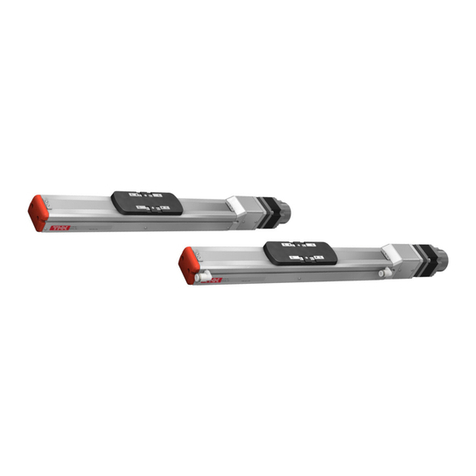
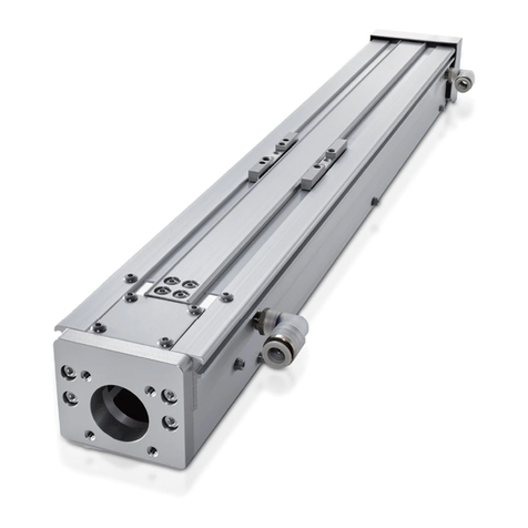
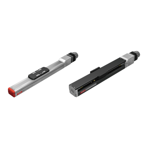
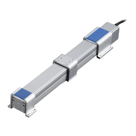
THK TH Series User manual

INSTRUCTION MANUAL
TH
THK Electrical Actuator Universal Series
No.345M ver 2.00 E
www.thk.ru
тел. +7(499) 703-39-86

Table of Contents
i
TH
1. Introduction 1-1
1-1 Acknowledgment 1-1
1-2 About this manual 1-1
1-3 How to use this product 1-2
1-4 About product support 1-2
1-5 Product and company information 1-2
2. Safety precautions 2-1
2-1 Warning indications on safety 2-1
2-2 Safety precautions 2-1
3. Specifications 3-1
3-1 Basic specification 3-1
4. Structure and Model Numbers 4-1
4-1 Structure and part names 4-1
4-2 Model configuration 4-2
5. Storage and Transportation 5-1
5-1 Precautions to be observed for safe use 5-1
5-2 Precautions to be observed for prevention of product failures or damage 5-2
6. Installation and Operation 6-1
6-1 Precautions to be observed for safe use 6-1
6-2 Precautions to be observed for prevention of product failures or damage 6-2
6-3 Other precautions 6-3
6-4 Mounting method 6-4
7. Maintenance 7-1
7-1 Precautions to be observed for safe use 7-1
7-2 Precautions to be observed for prevention of product failures or damage 7-1
7-3 Daily inspection 7-2
7-4 Periodical inspection 7-2
7-5 Lubrication 7-3
7-6 Method for supplying grease 7-5
8. Appendix 8-1
8-1 Adjusting the belt tension for the belt drive specification 8-1
8-2 Wrapped motor specification (ball screw drive) 8-4
8-3 Static permissible moment 8-5
8-4 Permissible input torque 8-5
8-5 Introduction of the grease 8-6
8-6 Introduction of the grease gun unit 8-7
www.thk.ru
тел. +7(499) 703-39-86

1-1
TH
1. Introduction
1.
Introduction
1-1 Acknowledgment
Thank you for purchasing Universal Series TH.
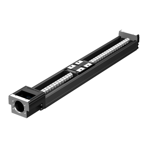
This product is an actuator using an aluminum base and is available in abundant variations.
We hope our creative inventions and unique technologies contribute to your further prosperity.
1-2 About this manual
1-2-1 Intended audience
The person in charge of designing embedded systems of the product and installing, wiring, and
maintaining the product, and the person who actually uses the product.
1-2-2 Using this manual
This manual describes correct handling methods and precautions for the product.
For the maximum performance and long life of the product, carefully read and understand this
manual to safely and correctly use the product.
If you use the printed version of this manual, be sure to keep it where the intended audience can
refer to it when needed.
1-2-3 Notice and attention
zDo not use or handle the product in the ways that are not described in this manual.
zDo not reproduce, reprint, or lend the whole contents or a part of this manual without permission.
zPlease note that description in this manual is subject to change without prior notice in the future,
due to improvements of the product or other reasons.
zWe have made all possible efforts to make the content of this manual accurate. However, if you
find any mistake or uncertainty in this manual, please contact THK Customer Support.
zDrawings show representative examples, and may differ from your product.
zNote that THK shall not be liable for any result incurred by applying this manual, regardless of the
reason.
zThis manual can be applied to custom products. However, the descriptions defined in the delivery
specification drawings or the delivery specification documents of those custom products should
take precedence over this manual.
* Custom products represent the products that have different materials and specifications from
those of the standard products on catalogs.
www.thk.ru
тел. +7(499) 703-39-86

1-2
TH
1. Introduction
1-3 How to use this product
zThis product cannot be used for the devices or systems that are used under the situations that
can affect human life.
zIf you consider using this product for special applications such as passenger movement vehicle,
medical, aerospace, nuclear power, and electric power devices or systems, be sure to consult
with THK in advance.
zThis product is manufactured under the strict quality control, however, that does not mean that
the product is free from failure.
zFor applications to the equipment that may suffer serious accidents or loss from the failure of this
product, install safety devices or backup devices that prevent such serious accidents or loss.
1-4 About product support
We have made all possible efforts to make the content of this manual accurate. However, if you find
any mistake or uncertainty in this manual, please contact our Sales Division and Customer Support,
or IMT Operation Division.
For the following information, please contact THK Customer Support.
zTechnical support for this product
1-5 Product and company information
To find the latest product and company information,
we recommend you to periodically access our website.
zWebsite URL: http://www.thk.com/
zTechnical support website URL: https://tech.thk.com/
www.thk.ru
тел. +7(499) 703-39-86

2-1
TH
2.
Safety Precautions
2-2 Safety precautions
This section describes important precautions that you must observe.
General
zWhile this product is operating or operable, do not enter the working area of any
moving part.
Otherwise, it may cause you to touch the moving part and injure you.
zWhile the motor or sensor is energized, do not move or install this product.
Otherwise, it may cause electric shocks, or cause malfunction that could lead to injury.
Installation and operation
zIf any moving part may fall by its own weight in vertical application or the like, provide
a safeguard for preventing the part from falling.
If any moving part falls, it may cause injury or damage.
zMotor wrap types do not have a safety device in case of timing belt breakage.
Install a safety device to the equipment for greater safety.
If any moving part falls, it may cause injury or damage.
zWhile this product is operating, do not touch any moving part or rotating part.
Otherwise, it may cause your hand to be caught and injured.
Warning
2-1 Warning indications on safety
This manual uses the following warning indications according to safety matters. The descriptions
next to warning indications on safety are important messages.
Be sure to observe those descriptions.
Warning
“Erroneous handling may cause death or serious injury
to a person”
Caution “Erroneous handling may cause injury to a person or
property damage only”
“Prohibitions (don’t)”.
“Obligations (do)”.
2.
Safety precautions
www.thk.ru
тел. +7(499) 703-39-86

2-2
TH
2.
Safety Precautions
Maintenance
zTurn off the machine (turning OFF power) before conducting any maintenance.
Otherwise, it may cause electric shocks, or cause malfunction that could lead to injury.
zIf two or more people are involved in the operation, confirm the procedures such as
sequences, signs, and abnormalities in advance, and appoint another person for
monitoring the operation.
Failure to do so may cause an unexpected accident.
General
zDo not stand on this product or the packaging box.
Otherwise, it may cause failures or damage, or cause falling that could lead to injury.
zDo not impact this product.
Otherwise, it may cause failures or damage, or injure you.
zDo not apply a load that exceeds the permissible level.
Otherwise, it may cause failures or damage, or cause abnormal operation that could lead to
injury.
* For your reference, see the Appendix, which contains the static permissible moment and
permissible input torque for each model number.
zDo not disassemble or alter this product.
Otherwise, it may cause foreign material to enter the product, which could result in fault or
adversely affect the performance or service life. It may also cause abnormal operation that
could lead to injury.
Unpacking
zBe careful not to hit your hands or body against protruded parts.
Otherwise, it may cause injury. or cause failures or damage of the product.
* Yellow tape is affixed to the product packaging to indicate the mounting locations of
protrusions or fragile parts. Handle with care.
zCheck whether the delivered product is the product you ordered.
Using a wrong product may cause malfunction that could lead to injury or fault.
zCheck whether the product has any fractured parts.
Using a fractured product may cause injury or fault.
* The packaging also contains a successful inspection certificate that guarantees product
quality. Please verify the contents.
* If you find any defect, contact our Sales Division.
Caution
www.thk.ru
тел. +7(499) 703-39-86

2-3
TH
2.
Safety Precautions
Transportation
zDo not drop or hit this product.
Otherwise, it may cause injury or fracture, or a functional loss.
zWhen transporting this product, do not hold any moving parts, the cover or the
bellows.
Otherwise, it may cause the product to fall, leading to injury, or cause failures or damage of the
product.
zWhen transporting this product, do not hold the motor, the sensor or the cable.
Otherwise, it may cause the product to fall, leading to injury, or cause failures or damage of the
product.
zWhen hoisting this product, use the aluminum base, and avoid applying load to any
other parts (side cover, end plate, motor, etc.)
Note) This hanging work must be carried out only by the qualified personnel wearing the
protective equipment such as helmets and safety shoes.
Otherwise, it may cause the product to fall, leading to injury, or cause failures or damage of
the product.
Installation and operation
zFirmly secure this product before operating it.
Failure to do so may cause abnormal operation that could cause injury, fault or fracture.
zIf anomaly occurs, immediately stop the machine.
Failure to do so may cause abnormal operation that could cause injury, fault or fracture.
zDo not exceed the maximum speed when using the product.
Otherwise, it may cause failures or damage, or cause abnormal operation that could lead to
injury.
For your reference, see the basic specification, which contains the maximum speed for each
model number at each stroke.
The pulley rotational speed of the belt driven specification has an upper limit of 1000 min-1.
zDo not use the failed and broken product.
Otherwise, it may cause injury or machine failure.
www.thk.ru
тел. +7(499) 703-39-86

3-1
TH
3. Specifications
3-1 Basic specification
The basic specification of TH is shown as follows. Do not exceed the following basic specification
when using the product.
Otherwise, it may cause failures or damage, or cause abnormal operation that could lead to injury.
3-1-1 Ball screw drive
Model
Ball screw
Lead
[mm]
Stroke
[mm]
Rated
speed
[mm/s]
Motor
Rated output
[W]
Maximum load capacity *1
[kg]
Maximum speed at each stroke *2 [mm/s]
Stroke [mm]
Horizontal
mount
Wall
mount
Vertical
mount ~790 970 1150 1330 1510 1690 1930 2170
TH20
5
190 to 2170
250
1000
2000
400
100 100 45 250 190 130 100 80 60 50 40
20 55 55 16 1000 780 570 430 340 270 210 170
40 11 11 9 2000 1570 1140 870 680 550 420 340
20 1000
2000 750 100 100 32 1000 780 570 430 340 270 210 170
40 40 40 14 2000 1570 1140 870 680 550 420 340
Model
Ball screw
Lead
[mm]
Stroke
[mm]
Rated
speed
[mm/s]
Motor
Rated output
[W]
Maximum load capacity *1
[kg]
Maximum speed at each stroke *2 [mm/s]
Stroke [mm]
Horizontal
mount
Wall
mount
Vertical
mount ~910 1090 1270 1450 1630 1870 2110 2350 2650
TH25
5
250 to 2650
250
310
1120
2240
750
120 120 50 250 190 140 110 90 70 50 40 30
10 120 120 35 310 310 260 200 160 120 100 80 60
25 70 70 25 1120 950 720 560 450 350 270 220 170
50 25 25 12 2240 1910 1450 1130 900 700 550 450 350
*1 The value when the acceleration/deceleration rate is 0.3G. Note that for lead 5mm this is the value at 0.15G.
*2
The maximum speed is the value restricted by the motor rotational speed (3000 min-1) or by the permissible rotational speed of the ball screw.
3-1-2 Belt drive
Model Stroke [mm] Motor rated output [W] Reduction ratio Max. speed [mm/s] Maximum load capacity (horizontal)[kg]
TH20 140 to 2660 400 1/3 2000 18
1/5 1200 60
750 1/3 2000 20
Model Stroke [mm] Motor rated output [W] Reduction ratio Max. speed [mm/s] Maximum load capacity (horizontal)[kg]
TH25 230 to 3590 750 1/3 2500 30
3.
Specifications
www.thk.ru
тел. +7(499) 703-39-86

4-1
TH
4.
Structure and Model Numbers
4.
Structure and Model Numbers
4-1 Structure and part names
Figs.1 and 2 show the structure and part names of this product.
End plate
Side cover
Cover
Nut bracket
Aluminum table
Stopper
Ball screw
LM guide with ball retainer
Aluminum base
Fig. 1 Structure and part names of actuator (ball screw driven)
Fig. 2 Structure and part names of actuator (belt driven)
End plate
Aluminum table
Stopper
Pulley case
Shaft
Timing belt
LM guide with ball retainer
Aluminum base
Timing pulley
* For details such as the dimensions and accuracy, see the delivery specification drawings, general
catalog of electrical actuators, or electrical actuator site.
If you have any question, contact THK.
www.thk.ru
тел. +7(499) 703-39-86

4-2
TH
4.
Structure and Model Numbers
4.
Structure and Model Numbers
4-2 Model configuration
The following is an example of model number coding for the mechanical parts only.
4-2-1 Ball screw drive
TH20 - 0970 - SW Q - B20 Q R1 G1 - B14 - C- 2- N
(1) Model number TH20, TH25
(2) Stroke 0970 : 970mm (190 to 2650 mm)
(3) LM guide model number SV : SSR-XV
SW : SSR-XW
HV : SHS-V
(4) LM guide with or without QZ No symbol : Without QZ
Q : With QZ
(5) Ball screw lead B05 : 5mm*1
B10 : 10mm*1
B20 : 20mm*1
B25 : 25mm*1
B40 : 40mm*1
B50 : 50mm*1
J05 : 5mm*1
J10 : 10mm*1
(6) Ball screw with or without QZ No symbol : Without QZ
Q : With QZ
(7) Motor mounting method/
With or without motor
0 : Direct coupling (without motor)
R1 : Non-standard side motor wrap*2 (without motor)
R2 : Reference side motor wrap*2 (without motor)
R3 : Bottom side motor wrap*2 (without motor)
1 : Direct coupling
(with motor, to be specified by the customer)
R4 : Opposite reference side motor wrap*2
(with motor, to be specified by the customer)
R5 : Reference side motor wrap*2
(with motor, to be specified by the customer)
R6 : Bottom side motor wrap*2
(with motor, to be specified by the customer)
*1 Ball screw leads you can select differ depending on the model number.
TH20: B05, B20, B40, J05
TH25: B05, B10, B25, B50, J05, J10
*2 Motor wrapping direction R2, R5
reference side
R1, R4 opposite
reference side
R3, R6
bottom side
Motor wrap direction
(As seen from side A)
(1) (2) (3) (4) (5) (6) (7) (8) (9) (10) (11) (12)
www.thk.ru
тел. +7(499) 703-39-86

4-3
TH
4.
Structure and Model Numbers
4.
Structure and Model Numbers
(8) Wrapped motor reduction
ratio
No symbol : Direct coupling
G1 : Wrap 1/1
G2 : Wrap 2/3
G3 : Wrap 1/2
(9) End plate/
Motor mounting plate
B
D
F
J
B14
D11
D14
D19
F11
F14
J14
J16
J19
(10) Cover/bellows N : Without cover
C : With cover
J : With bellows
(11) Sensor N : None
6 : Photo sensor EE-SX674 3 units (OMRON Corporation)
H : Proximity sensor (N.O. contact) GX-F12A 3 units
(Panasonic Industrial Devices SUNX Co., Ltd.)
J : Proximity sensor (N.O. contact) GX-F12A 1 unit
Proximity sensor (N.C. contact) GX-F12B 2 units
(Panasonic Industrial Devices SUNX Co., Ltd.)
(12) Cable chain N : None
B : TKP0180W40R37 (Tsubakimoto Chain Co.)
C : TKP0180W40R50 (Tsubakimoto Chain Co.)
J : KSH-24L-42 (THK)
K : KSH-32WL-60 (THK)
L : KSH-32WL-110 (THK)
* For details, see the general catalog of electrical actuators or the electrical actuator site.
www.thk.ru
тел. +7(499) 703-39-86

4-4
TH
4.
Structure and Model Numbers
4.
Structure and Model Numbers
4-2-2 Belt drive
TH20 - 0920 - SW Q - EH - 0 B1 G3 03 - C– 6– J
(1) Model number TH20, TH25
(2) Stroke 0920 : 920mm (140 to 3590 mm)
(3) LM guide model number SW : SSR-XW
HV : SHS-V
(4) LM guide with or without QZ No symbol : Without QZ
Q : With QZ
(5) Driving method EH : Belt
(6) With or without motor 0 : Without motor
1 : With motor
(7) Motor bracket N : None
B1
B2
(8) Belt specification speed reducer No symbol : Without speed reducer
G1
G2
G3
G4
G5
G6
G7
G8
(9) Belt specification reduction ratio No symbol : Without speed reducer
03 : 1/3
05 : 1/5
09 : 1/9
15 : 1/15
(10) Cover/bellows N : Without cover
C : With cover
J : With bellows
(11) Sensor N : None
6 : Photo sensor EE-SX674 3 units (OMRON Corporation)
H : Proximity sensor (N.O. contact) GX-F12A 3 units
(Panasonic Industrial Devices SUNX Co., Ltd.)
J : Proximity sensor (N.O. contact) GX-F12A 1 unit
Proximity sensor (N.C. contact) GX-F12B 2 units
(Panasonic Industrial Devices SUNX Co., Ltd.)
(12) Cable chain N : None
B : TKP0180W40R37 (Tsubakimoto Chain Co.)
C : TKP0180W40R50 (Tsubakimoto Chain Co.)
J : KSH-24L-42 (THK)
K : KSH-32WL-60 (THK)
L : KSH-32WL-110 (THK)
* For details, see the general catalog of electrical actuators or the electrical actuator site.
(1) (2) (3) (4) (5) (6) (7) (8) (9) (10) (11) (12)
www.thk.ru
тел. +7(499) 703-39-86

5-1
TH
5.
Storage and Transportation
5.
Storage and Transportation
5-1 Precautions to be observed for safe use
zDo not drop or hit this product.
Otherwise, it may cause injury or fracture, or a functional loss.
zWhen transporting this product, do not hold any moving parts, the cover or the bellows.
Otherwise, it may cause the product to fall, leading to injury, or cause failures or damage of the
product.
zWhen transporting this product, do not hold the motor, the sensor or the cable.
Otherwise, it may cause the product to fall, leading to injury, or cause failures or damage of the
product.
zWhen hoisting this product, use the aluminum base, and avoid applying load to any other
parts (side cover, end plate, motor etc.)
Note) This hanging work must be carried out only by the qualified personnel wearing the protective
equipment such as helmets and safety shoes.
Otherwise, it may cause the product to fall, leading to injury, or cause failures or damage of
the product.
zWhen carrying this product, hold the bottom face of the aluminum base. Most models of
this product are heavy articles (20 kg or heavier). Two or more people should hold the
product as necessary.
Otherwise, it may cause the product to fall, leading to injury, or cause failures or damage of the
product.
* For more information on the weight of the product, see the general catalog of electrical
actuators or the electrical actuator site.
Caution
www.thk.ru
тел. +7(499) 703-39-86

5-2
TH
5.
Storage and Transportation
5.
Storage and Transportation
5-2
Precautions to be observed for prevention of product failures or damage
zSince using an adverse storage environment may cause failures, store the product in the
environment described below:
· Place at ambient temperature within the following storage temperature range
Ball screw drive storage temperature: -10°C to 50°C
Belt drive storage temperature: 0°C to 50°C
(no freezing or condensation, TH main unit only)
* With the packaging unopened
· Place with non-corrosive gas nor flammable gas
· Place with little dust, salt or metallic powder
· Location where water, oil or chemical does not come in contact with the product
· Location where a vibration or shock does not transmit to the main unit
zThis product is provided with antirust treatment and sealed before being packed. When
storing the product, enclose it in a package designated by THK and store it in a
horizontal orientation while avoiding high temperature, low temperature and high
humidity.
zDo not apply an excessive load on the package, otherwise, it may cause failures or
damage.
www.thk.ru
тел. +7(499) 703-39-86

6-1
TH
7.
Installation and Operation
6.
Installation and Operation
6-1 Precautions to be observed for safe use
zIf any moving part may fall by its own weight in vertical application or the like, provide a
safeguard for preventing the part from falling.
If any moving part falls, it may cause injury or damage.
zWhile this product is operating, do not touch any moving part or rotating part.
Otherwise, it may cause your hand to be caught and injured.
zFirmly secure this product before operating it.
Failure to do so may cause abnormal operation that could cause injury, fault or fracture.
zIf anomaly occurs, immediately stop the machine.
Failure to do so may cause abnormal operation that could cause injury, fault or fracture.
zDo not exceed the permissible rotation speed when using the product.
Otherwise, it may cause failures or damage, or cause abnormal operation that could lead to injury.
For your reference, see the specification, which contains the maximum speed for
each model number at each stroke.
The pulley rotational speed of the belt driven specification has an upper limit of 1000 min-1.
zDo not use the failed and broken product.
Otherwise, it may cause injury or machine failure.
Caution
Warning
6.
Installation and Operation
www.thk.ru
тел. +7(499) 703-39-86

6-2
TH
7.
Installation and Operation
6.
Installation and Operation
6.
Installation and Operation
6-2
Precautions to be observed for prevention of product failures or damage
zSince using in an adverse operating environment may cause failures use the product in
the environment described below.
· Place at the following operating temperature range
Operating temperature: 0°C to 40°C (ambient humidity 80% RH or less, no freezing or
condensation)
* If you desire to use the product outside of the operating temperature range, contact THK.
· Place with non-corrosive gas nor flammable gas
· Place with little dust, salt or metallic powder
· Location where water, oil or chemical does not come in contact with the product
· Location where a vibration or shock does not transmit to the main unit
zCertain types of coolants may cause trouble to the function of the product. If using the
product in an environment where the coolant may enter into the product, contact THK.
zPrevent foreign material such as dust or metallic powder from entering the product since
it may cause abnormal wear or shorten the service life.
If foreign material enters the product, take dust-proof measures that match the service
atmosphere.
zThe mounting surface for this product must be a machined plane or have accuracy
equivalent to the machined plane. If the surface is insufficiently accurate, it may
adversely affect the performance or the service life. In addition, be sure to mount the
product on a sufficiently rigid base.
zUse the product within the stroke range.
Take care as the stroke is shorter, particularly for types with bellows.
* For more information on the stroke, see the general catalog of electrical actuators or the
electrical actuator site.
zBe careful not to let the parts to be mounted on the table of this product interfere with
any other parts near the stroke end.
zTake care if types with covers are used in any other position than horizontal (upside-
down or wall-mounted), as the deflection of the cover may cause it to come in contact
with components mounted on the table.
* For details, please contact THK.
zUse thin head screws for pulley cover installation if using the ball screw driven wrapped
motor specification. Take care when mounting or dismounting the pulley cover as the
heads of the screws may become scratched. The appearance and tightening torque
(standard) are as follows.
* Tightening torque (standard)
: 75 N·cm --- Steel bolt (standard specification)
: 46 N·cm --- Stainless steel bolt
Thin head screw appearance
www.thk.ru
тел. +7(499) 703-39-86

6-3
TH
7.
Installation and Operation
6.
Installation and Operation
6.
Installation and Operation
zCheck that there is no tool or bolt in the product before operating it.
zThe stoppers attached to both stroke ends are not for positioning. Do not use them for
positioning.
zAnti-rust oil is applied on the product. Thoroughly wipe off the oil before operating the
product. In addition, supply grease after trial run, and then use the product.
In addition, the standard models contain the THK AFB-LF grease.
* Those with Lubricator QZ can be used without greasing.
Grease nipple is not attached for those with QZ
zFor the belt driven specification, the belt tension is adjusted before shipment, but may
be lowered by the initial elongation of the belt. We recommend that you check the belt
tension before use and adjust it appropriately.
Refer to the appendix [Adjusting the Belt Tension].
zThe photomicro sensors do not have a waterproof or dust-proof structure. Do not use it
in a location where much dust or oil mist is present, or where water, oil or chemical
directly or indirectly flies. For other detail information, see the catalog issued by the
sensor manufacturer.
* Standard sensors
· EE-SX674: OMRON Corp.
6-3 Other precautions
zIf you use proximity sensors close to each other, they may interfere with each other. To
avoid such mutual interference, consider taking an appropriate measure such as keeping
a sufficient distance between the sensors and using sensors of different frequencies.
For details, see the catalog issued by the sensor manufacturer.
zIf a stainless steel sensor dog is used when a proximity sensor is used, note that the
detection distance is shorter than that of an iron dog.
For details, see the catalog issued by the sensor manufacturer.
* Standard sensors
· GX-F12A, GX-F12B: Panasonic Industrial Devices SUNX Co., Ltd.
zFor selection and handling of a motor, see the respective catalog and instruction manual
issued by the motor manufacturer.
For data required to select a motor, see the catalog for your reference.
zFor handling and mounting of a speed reducer, see the respective catalog and instruction
manual issued by the speed reducer manufacturer [Nidec-Shimpo].
zFor selection, handling and mounting of a coupling, see the respective catalog issued by
the coupling manufacturer.
Check necessary data such as permissible torque, eccentricity, deflection angle and tightening
torque of the assembly bolt.
zFor selection and handling of cable chains, see the respective catalog issued by the
cable chain manufacturer.
www.thk.ru
тел. +7(499) 703-39-86

6-4
TH
7.
Installation and Operation
6.
Installation and Operation
6.
Installation and Operation
6-4 Mounting method
For the TH model, use the slots at the bottom of the aluminum base to secure it to the mounting
surface from below with the base mounting nuts (attached) and hexagon socket head cap screws.
See Fig. 3.
Make sure the screws are attached at equal intervals of roughly 250 to 300 mm.
The number of base mounting nuts is shown in Table 1, and the outline drawing thereof in Figure 5.
Mounting
surface
Base mounting nuts
Aluminum base
fixing bolts
A Part
Fig. 3 Mounting drawing for TH
Note) Use the bolt with the most appropriate length. See Fig. 4.
Optimal bolt length
* Bolt is too short, easy to loosen.
* Bolt is too long, with backlash.
Fig. 4 Detailed Diagram: A Part
www.thk.ru
тел. +7(499) 703-39-86

6-5
TH
7.
Installation and Operation
6.
Installation and Operation
6.
Installation and Operation
M8 through
5.2
71
5.8
8.5
M8 through
6
21
7.5
51
5.7
9.2
17
10
15
5.7
TH20 Type TH25 Type
Fig. 5 Outline drawing of base mounting nuts
Base length
[mm] ~460 ~700 ~820 ~1240 ~1420
Qty. 4 6 8 10 12
Base length
[mm] ~1780 ~2200 ~2500 ~3000 ~3460
Qty. 14 16 18 20 24
Base length
[mm] ~3700 ~3820 ~3940
Qty. 26 28 30
Table 1 Number of attached base
mounting nuts
www.thk.ru
тел. +7(499) 703-39-86

7-1
TH
7. Maintenance
7.
Maintenance
7-1 Precautions to be observed for safe use
zTurn off the machine (turning OFF power) before performing maintenance.
Otherwise, it may cause electric shocks, or cause malfunction that could lead to injury.
zIf two or more people are involved in the operation, confirm the procedures such as
sequences, signs, and abnormalities in advance, and appoint another person for
monitoring the operation
Failure to do so may cause an unexpected accident.
zWhen handling grease, wear safety goggles and protective gloves.
If grease gets into eyes or touch the skin, it may affect your body such as causing inflammation.
zDo not apply grease to a flame, firework, or high-temperature object.
Otherwise, it may ignite the grease, which could cause fire.
* For other information on handling grease, see the precautions indicated on the grease package
or catalog. SDS (Safety Data Sheets) for THK original grease are available for download from the
THK technical support website. If you have any questions, contact THK.
7-2
Precautions to be observed for prevention of product failures or damage
zTo have this product fully exerts its functions, it is essential to lubricate the product. Be
sure to supply grease on a regular basis.
Using the product with insufficient lubrication may shorten the service life.
zDo not let foreign material enter the LM guide or ball screw.
Otherwise, it may cause failures, or could adversely affect the performance or service life.
zBe careful not to let foreign material get caught between the gears of the timing belt and
pulley.
Otherwise, it may cause failures, or could adversely affect the performance.
zDo not mix different types of greases.
Otherwise, it may affect the performance.
Caution
Warning
www.thk.ru
тел. +7(499) 703-39-86
This manual suits for next models
2
Table of contents
Other THK Controllers manuals
Popular Controllers manuals by other brands
BIFFI
BIFFI EFS2000v4 Instructions and operating manual
Kutai electronics
Kutai electronics ADVR-250 Operation manual
Offshore
Offshore 3350-FTC Installation and operating instructions
Kirby Morgan
Kirby Morgan SuperFlow 350 Regulator manual

Centork
Centork 482 Series Installation and Maintenance user Manual
Milnor
Milnor MilTouch MWF27Z8 Series Operator's guide
