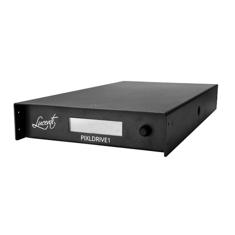
Lucenti BLACKWAVE PIXLDRIVE8 PRO User manual

1
EN
BLACKWAVE
PIXLDRIVE8 PRO CONTROLLER
QUICK START GUIDE
RELEASE V1.0

2
QUICK START GUIDE
LUCENTI LIGHTING
This PixlDrive8 Pro is the rst product co-developed with KLSTR.
KLSTR is a universal hardware platform especially designed for lighting devices.
With the purchase of a KLSTR enabled product you can control, congure and monitor all
your KLSTR enabled products using our KLSTR application.
KLSTR is designed to simplify the control and conguration of lighting setups.
In this quick start guide we will show you how easy and intuitive the KLSTR application is.

3
GETTING PREPARED 4
DOWNLOAD THE DESKTOP APP 4
INSTALLATION 4
WINDOWS 4
MACOS 5
GETTING STARTED WITH KLSTR 7
CONNECT YOUR DEVICES 7
ETHERNET 7
DAISY CHAINING 7
STAR AND RING TOPOLOGIES 8
PIXLBUS 11
SELECT INTERFACE 12
NETWORK TOPOLOGY VIEW 13
NETWORK DEVICES AND SUBDEVICES 14
DEVICE CONFIGURATION 15
DISCOVERY 15
OVERVIEW 16
PORT SPECIFIC 17
CONTROL 18
DEVICE MODE 18
EDMX 18
MERGING 18
START ADDRESS 18
DENSE MAPPING 18
EFFECTS ENGINE (STANDALONE OPERATION) 19
TEST PATTERNS 19
BLACKOUT 19
NETWORK 19
FIRMWARE 19
TABLE OF CONTENTS

4
GETTING PREPARED
GETTING PREPARED
First of all you will need to download the KLSTR control application called KLSTR.CTRL.
We are building and adding new features continuously, both on the device rmware and
the application.
You can download the latest version of our application on latest.KLSTR.tech.
The application is available for Windows 10 and macOS.
Windows
First, download the zip archive containing the application and unzip it.
Install the application by running the .exe le in the folder.
After installation the application will launch itself.
Windows Firewall settings
When you start the KLSTR application for the rst time, Windows will ask you if the application
is allowed to pass through the rewall.
Press the ALLOW ACCESS button.
Download the desktop app
Installation

5GETTING PREPARED
macOS
First, download the dmg containing the application and mount it. Drag the application to the
applications folder.
Go to your applications folder and open the application. When you start the KLSTR application
for the rst time, macOS might ask you if you want to open the application because it was
downloaded from the internet. Conrm that.
Depending on your macOS settings, the application might not be permitted to start.
To x this, open your SYSTEM PREFERENCES, go to SECURITY AND PRIVACY :

6 GETTING PREPARED
To x this, open your SYSTEM PREFERENCES, go to SECURITY AND PRIVACY :
Click on “Open Anyway” to start the application.

7GETTING STARTED WITH KLSTR
Ethernet
Every KLSTR.one device has 3 ethernet ports, referred to as port A, B and C.
KLSTR.one is built on a managed ethernet switch that allows you to connect your devices in every
topology that suits you best.
There are a couple of rules to follow to optimize your system. We will quickly explain:
Daisy Chaining
The physical location of devices generally invites connections to make use of a daisy chain.
To forward data over ethernet, the device needs to have power. As a result, in case of an
unpowered device in the chain, the devices “afterwards” in the chain will not be connected to
the network.
Of course, that would be problematic in case of an unexpected power failure.
However, to allow users to safely connect devices in a daisy chain, port A and port B are tted
with an internal relay that physically connects port A to port B when the device is unpowered.
Connect your devices
In the example above, the power of device #2 is interrupted. The internal bypass relay will
close and physically connect port A to B: this means that port B from device #1 will be directly
connected to port A of device #3 on the drawing.
GETTING STARTED WITH KLSTR
In this example above, we’ve connected port C of device #2 to port A of device #3. Device #2 has
a power malfunction. All devices further on the line ‘after’ device #2 are also impacted, because
they are not connected to the network anymore. This could have been easily avoided by using
port B on device #2 to connect it to device #3.
>> One simple rule of thumb : when daisy chaining devices, only use PORTS A & B.

8GETTING STARTED WITH KLSTR
Star and Ring topologies
Introducing the relay protects your ethernet based lighting system from power failure in your
system, however it does not protect your setup against faulty cables, connectors that become
loose or ethernet / dmx converters that malfunction.
With KLSTR.one we introduce real redundancy to your lighting rig by oering the possibility to
create rings in your cabling.
In this example we connected 8 devices in a ring. daisy chaining the devices and connecting the
last controller back to the rst.
KLSTR will detect this ring conguration and will automatically congure ONE of these cables as
a backup path. This will be indicated in the application as a green dotted cable.

9GETTING STARTED WITH KLSTR
In case of a change in the cabling topology, KLSTR will activate this backup path and send the
data through the other path.
The broken cable will be indicated with a red dotted line.
Any combination of topology can be created. KLSTR will automatically congure the necessary
connections to reach all devices and create all the necessary backup paths.
Keep in mind that connecting devices in a daisy chain behind a ring is best established with port
A and B as we can still reach the device when in case of a power failure.

10 GETTING STARTED WITH KLSTR

11GETTING STARTED WITH KLSTR
A PixlDrive8 Pro controller sits between a power outlet and a collection of xtures that understand
the ‘PixlBus’ protocol. The PixlBus provides power and data to all connected xtures. The following
gures focus on connecting BlackWave Collection BW-100 and BW-50 bars to the controller.
First connect all BlackWave pixel bars to each other.
Connect the rst pixel bar to the controller.
Connect the controller to an available power outlet.
Connect the computer with the KLSTR application to the controller.
PixlBus

12 GETTING STARTED WITH KLSTR
Connect the computer to the same ethernet network where your KLSTR devices are connected to
each other. When you start the KLSTR.CTRL application, you need to select the ethernet interface
where your devices are connected to.
In the top left side of your screen, open the KLSTR item in the menu and select SELECT INTERFACE.
The pop-up window which follows, allows you to select one of your available ethernet interfaces.
Select the interface you want the KLSTR application to use.
Automatically, KLSTR.CTRL will discover all connected KLSTR devices in your network.
The application will bring you to the NETWORK TOPOLOGY window.
Communication between the KLSTR application and the devices will take place over IPv6.
No need to congure any ip settings of your computer.
TIP: When connecting your ethernet cable after you open up the SELECT INTERFACE menu:
Press the reload button to see all your actual connected interfaces.
Select interface

13GETTING STARTED WITH KLSTR
The Network Topology tab will draw all your KLSTR devices in the network and show you the
cables that interconnect KLSTR devices. When you point your mouse over one of the cables, it will
show you from which port to which port your cable runs.
You can move devices on the screen to match their representation in the real world.
The application is able to create a good starting point by selecting the “Auto distribute” function
that can be found under the “Arrange” button.
Network Topology view

14 GETTING STARTED WITH KLSTR
To create a uniform look you are able to distribute the selection evenly by using the “Distribute
horizontally” or “Distribute vertically” function found under the same button.
Once you’re done with creating the visual representation of your set you can save the location of
the device on the grid by clicking on “Save positions”, found under the “View” button.
The grid locations are stored on the devices in the network, so when you restart the application or
another user comes online, you can restore the screen by pressing the “Load positions” button.
We distinguish two types of devices : the ones directly connected to the network (Network
Devices) and the ones who are in need of an intermediary (Subdevices).
Examples of these intermediaries are DMX Nodes, Pixel converters or controllers like the Lucenti
PixlDrive8 Pro. They act as a translator, making non-networked devices available on the KLSTR
network.
The PixlDrive Pro 8 is capable of showing the connected order of the connected PixlBus devices.
First of all we need to give the pixelcontroller the command to start a discovery on all ports.
Therefore we need to go to the device conguration menu.
Network Devices and Subdevices
All your devices will be distributed across the screen.
While holding the Shift button on your keyboard, you can drag with your mouse and select
multiple devices.
If you select multiple devices, you are able to align them horizontally or vertically. This function
makes it very easy to align devices that hang on the same truss or pipe.

15DEVICE CONFIGURATION
All congurations of a device can be accessed by pressing the gear symbol ( ).
Click it, and the KLSTR application will open up the device conguration page.
The controller features intelligent enumeration and auto-addressing of all connected xtures
through the smart PixlBus. It suces to connect all xtures together, connect the rst to a desired
port on the controller and perform a discovery to let the system discover all xtures and auto
congure all necessary parameters. This process can take up to 4 seconds.
To trigger the discovery process, Press the Discovery icon in the Conguration screen.
After a discovery:
»All connected xtures receive a unique and incremental PixlBus ID. The rst xture after the
controller has ID 1, the second ID 2, …
»BlackWave pixel xtures will display their ID on start-up using white LEDs.
»The controller keeps an internal list of all connected xtures, with their type and manufacturer,
containing all necessary parameters such as pixel type and count.
»A pixel map is automatically generated, reserving the necessary DMX universes and channels
to drive each pixel of each connected xture.
»The controller is now ready for use.
Discovery
DEVICE CONFIGURATION

16 DEVICE CONFIGURATION
The overview will now show you the devices discovered on each port.
Also, it will give you an overview of the current settings.
To easily identify all the devices behind a certain port, toggle the Lamp icon for the port you want
to identify.
You can get port specic information by pressing the port tab on the left. This will open the port
specic detail page.
Overview

17DEVICE CONFIGURATION
To easily identify a single device, toggle the Lamp icon for the device you want to identify.
Port specic

18 DEVICE CONFIGURATION
Device mode
The controller can be switched to one of 4 dierent device operating modes. The controller will
store and start up in the selected device mode after reboot.
eDMX
Slave to external Ethernet DMX (eDMX) input.
The controller receives data from an external lighting controller or software.
Select the protocol you want to use.
Both Art-Net and sACN (E1.31) are supported, and can be selected both at the same time.
Merging
When a device receives data from multiple sources on the same universe, KLSTR will merge
them together (HTP). This allows you to use multiple sources at the same time, for example
a lighting console and media server both sending data to the device, without the need for
an external merging engine.
Start address
The controller needs an address from where it will start assigning addresses.
Enter the start address of a controller.
Dense mapping
After the discovery process the controller will assign a starting address to each PixlBus
device found on the ports.
This assignment will be done from port 1 to port 8 from the rst device till the last.
starting at the start address and adding device by device as long as the device t inside
a universe. If the device does not t in a universe it will jump to the next universe. This
sometimes creates spaces at the end of the universe.
When dense mode is enabled , the controller will iterate a second time over the devices tting
all devices that have a small enough channel count at the end of the universe. This optimizes the
number of universes a controller needs.
Control

19DEVICE CONFIGURATION
Eects Engine (standalone operation)
The controller is equipped with a powerful internal eect engine that can dynamically generate
colors and animations for all connected xtures. Conguration options for the engine appear
when the option is selected.
Test patterns
The controller is equipped with a set of built-in test patterns that run on all connected xtures. A
list with all available test patterns appears when the option is selected.
Blackout
Display black (no light) on all connected xtures.
Network
Communication between your KLSTR application and the device will be IPv6, no need to worry
about IPv4 addresses.
We highly recommend you to use sACN as input source when using eDMX.
With sACN you don’t have to worry about IPv4 settings.
WHEN using Art-Net, make sure your lighting controller or media server is in the same
IPv4 range as the devices.
IPv4
IP Address: The current IPv4 address for the wired Ethernet connection.
Netmask:
The current IPv4 netmask address for the wired Ethernet connection.
Firmware
The KLSTR technology will be constantly evolving, giving your devices new capabilities.
In order to do this, we will need to update the internal rmware from time to time.
Download the device rmware, select the rmware.
Once the upload is completed your system will restore like before.
Table of contents
Other Lucenti Controllers manuals