Luhrs 31-Open Quick start guide

31-Open
Rigging Manual
Page:
1 of 15 Total Task Time:
N/A

31-Open
Rigging Manual
Page:
2 of 15 Total Task Time:
N/A
Figure: 1 is showing the boat on the
truck as it arrives at your dealership.
The boat will be shrink-wrapped with
netting over it. The shrink wrap and
netting will have to be removed before
rigging the boat. Look the underside of
the boat over for any shipping damage
that might have happened during
delivery and document if any is found.
In figure: 2 you notice that the sunshade
and console are shipped separately from
the boat on its own cradle. This will be
secured on the front of the truck. Look
over sunshade and console for any
shipping damage and document. The
sunshade needs to be unsecured from
cradles before setting on top of hardtop.
Figure: 3 is showing the tube that the
steering lines and the electronic control
cable and nav light harness come up
from the engine room to the upper
console. They will be inside the ladder
tubing for shipment. There is a
retrieving line tied to them that gets
pull and will pull up the steering lines
and cable from the engine room. It is
requested that a second person goes
into the engine room and helps feed
lines to insure that the lines don’t get
kinked while pulling into tube.
Figure: 2
Figure: 3
Figure: 1

31-Open
Rigging Manual
Page:
3 of 15 Total Task Time:
N/A
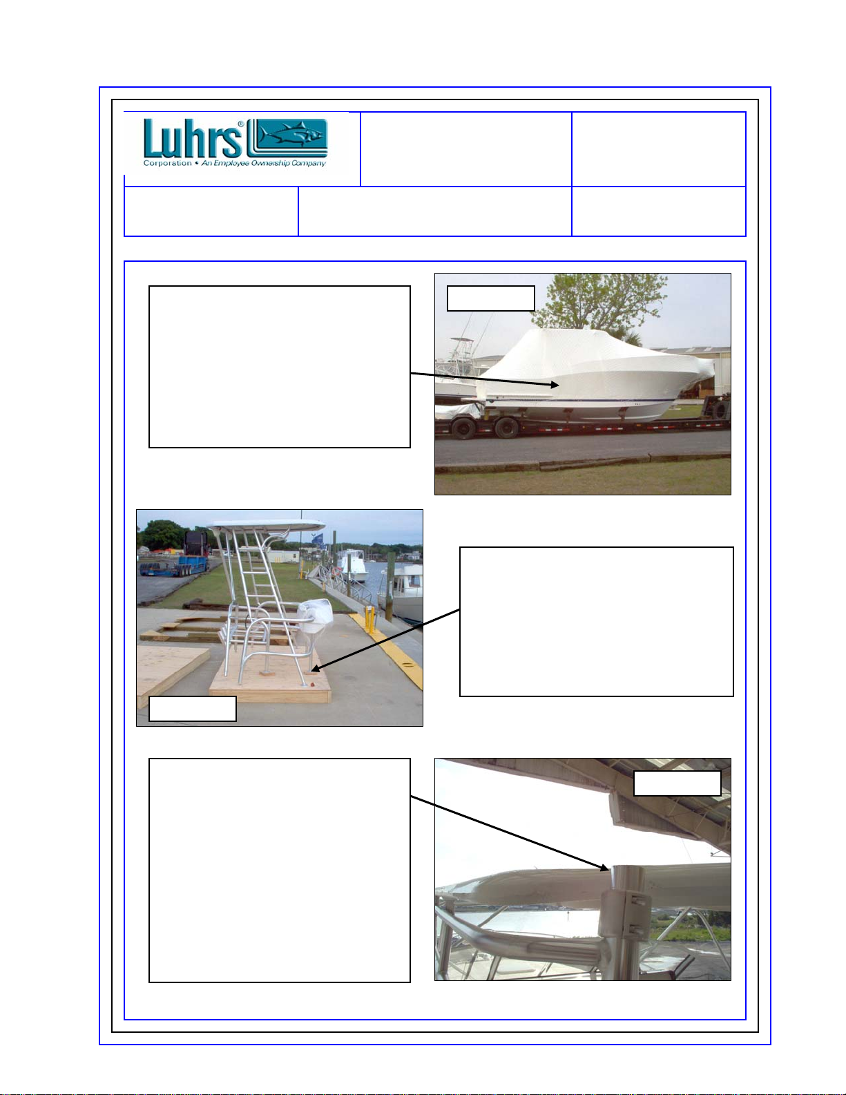
Once all lines are pulled snug as
shown in figure: 4.The console and
sunshade are ready to be put on
top of the hardtop. The whole
upper station can be picked up as
one piece. Make sure to support
the console when lifting. Best
procedure is to use a forklift and
pick up the upper station while still
on the cradle and slide upper
station off cradle once you get it
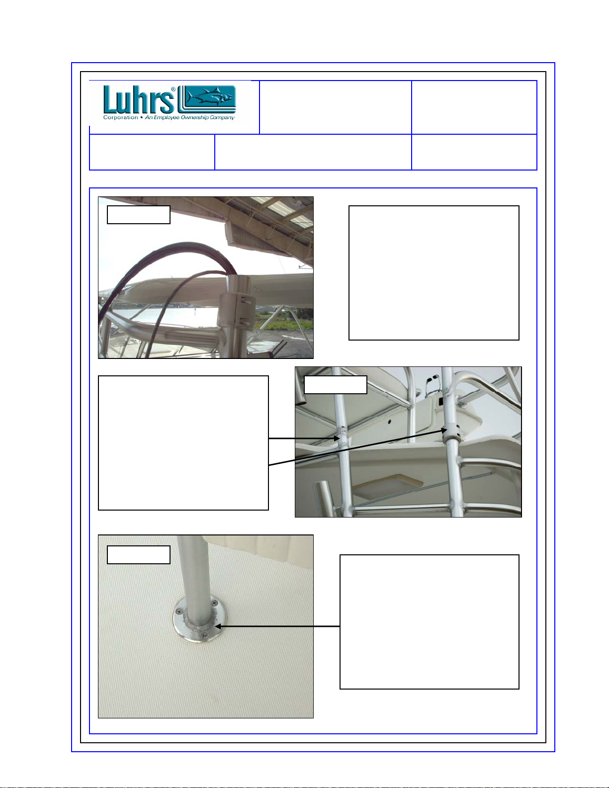
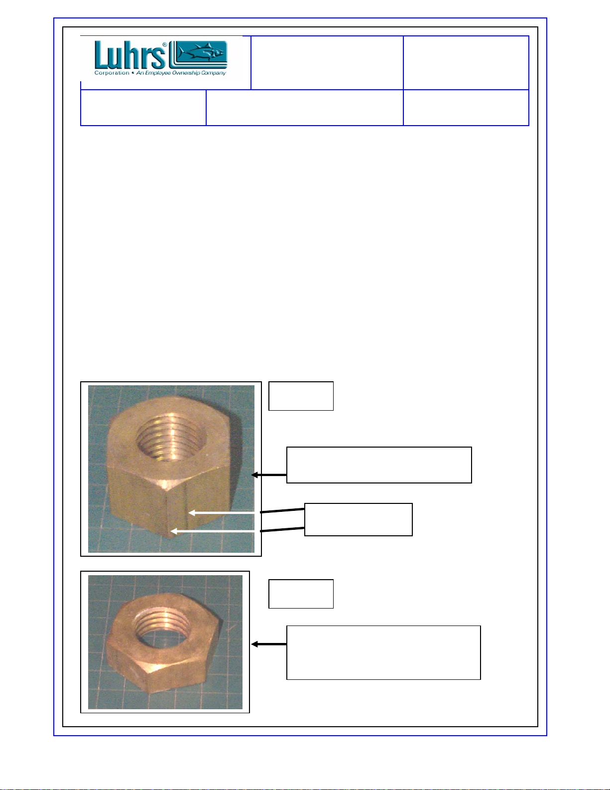
Figure: 5 is showing how to
connect the aft legs of the upper
tower to the ladder after the upper
station is in place. The outside leg
has a collar that tightens with allen
bolts and the inside tube connects
with allen bolts into each other.
Both the collar and allen bolts are
provided in the loose gear kit. This
will be the same on both the Port &
Starboard aft legs.
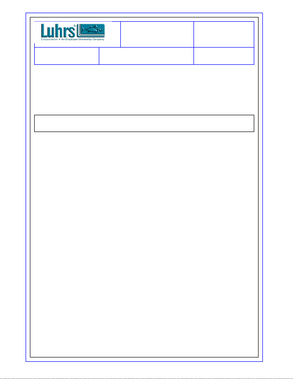
Figure: 6 is showing the base of the
seat pad. Install using ¼ x 20 x 1” f/h
screws provided in rigging kit to
secure seat. There will be pre-drilled
holes that have been pre-tapped at
the factory that you line holes in pad
up with for ease of installation. Make
sure to use 5200 sealant provided in
loose gear to get a water tight seal.
Do this with both pads that are under
upper bench seat.
Figure: 5
Figure: 6
Figure: 4

`` 31-Open
Rigging Manual
Page:
4 of 15 Total Task Time:
N/A
Figure: 7
Figure: 7 is showing the foot pad
under the console. To secure use
¼ x 20 x 1” f/h screws to pre-drilled
and pre-tapped holes done at the
factory. Line holes up on hardtop
with pad holes and secure.
Remember to use 5200 sealant for
a water tight seal. This will be done
on all 4 pads under to upper
console.
Figure: 9 shows the hole into the
console in which all the harness feed
into the upper console through the
starboard console tube. Secure tube
with ¼ x 20 x 1-1/4” f/h screws with a
¼” washer, lock washer & hex nut.
Tighten and then use ¼” cap nut to
dress it off. Make sure to use 5200
sealant for water tight seal.
Figure: 9
Figure: 8 & 8a shows a picture of the
starboard fwd console tube with all the
harnesses already ran through it. It will
be secured to the Fwd hardtop leg for
shipment. Undo and feed harnesses
through the hole in the console in
figure: 9. Use 5/16” x 1” f/h machine
screws to secure fwd leg to hardtop
into pre-drilled and pre-tapped holes
that were set up at the factory.
Remember to use 5200 for water tight
seal. Port fwd leg will secure the same
way.
Figure: 8
Figure: 8a

`
Figure: 10 shows the harness
connections. The harnesses will
plug together by size of plug and
color to color plug ins. Once
plugged together, put a tie wrap
around plug to help from
possibility of coming apart.
Figure: 10
Page:
5 of 15 Total Task Time:
N/A
31-Open
Rigging Manual
Figure: 11
Figure: 11 is showing the
Glendinning electronic control
hook up.
Figure: 12 is showing the
steering lines hook up. The Port
line will be marked with Red tape
and the Starboard will be marked
with Green tape. Station to
Station will be black.
Figure: 12

PROPELLER INSTALLATION
The proper procedure regarding the installation of marine propellers is detailed here for
the benefit of dealers, service people, and customers alike. This is to insure proper
installation in accordance with the A.B.Y.C. and good industry practice.
A. Inspect propeller for shipping damage when removing from box. If the box is damaged, check
the propeller carefully.
B. Clean any burrs, tape residue, or any other foreign material from the propeller end of the
shaft, and key seat.
C. Carefully slide the propeller onto the shaft as far as it will go without the key installed.Mark
the shaft with a pencil. Check the fit of the taper by attempting to rock the propeller while tight
on the shaft. No rocking should occur.
D. Carefully remove the propeller and set aside. Fit the key into the key seat on the shaft and
within the propeller hub with a fine mill file or fine Emory on a flat surface. File only the key.
The key seat width may vary from nominal to minus .001” (nominal + .000/-. 001”). In good
practice this means that the key seat width in the propeller can vary from the key seat width
in the shaft by as much as .001”. The key must be filed (lengthwise) to achieve a good fit for
each key seat. A good fit has been achieved when the key can be slid into position with no
slack in the key seat, and with no hammering. A key that is too tight or too loose can damage
the shaft or propeller hub, or both.
Proper Method of Propeller Shaft Key Stock Installation.
The A.B.Y.C. and the S.A.E. standards specify an allowable tolerance in key seat width for 1
½” and 1 ¾” diameter shafts of nominal to minus .001 (nominal +001”/-. 001”). The following
table lists allowance minimum and maximum key seat widths for each shaft size.
Shaft Size Maximum Key Seat Width Minimum Key Seat Width
Note: If Rocking occurs, contact Luhrs / Mainship Corporation customer
service for corrective action.
Total Task Time:
N/A
31-Open
Rigging Manual
Page:
6 of 15

1 ½” .3750” .3740”
1 ¾” .4365” .4375”
The problem that presents itself here is the probability of the various key seat widths encountered
when installing a propeller.
A. Place the key into the key seat on the shaft. Be sure the key is correctly oriented.
B. Slide the propeller up onto the shaft, making sure the key does not ride up and forward within the
key seat. The propeller hub should position itself to the mark previously made. If the hub does not
align itself with the mark, the key has not been properly fit. Refit the key.
C. While holding the propeller in place, start the large nut (Chamfered Side of Nut towards
Propeller, see figure #13) until hand tight to prevent movement and keep the propeller from
falling off.
D. Place a wood block between the blade and the ground, then tighten the large shaft nut. Install
and tighten the smaller jam nut, see figure #14 (Chamfered Side of Nut Away From Propeller).
Insert and bend over the cotter pin. Remove the block of wood.
31-Open
Rigging Manual
Page:
7 of 15
Figure #13
Figure #14
Large propeller nut. Install first with
chamfered side towards to propeller.
Chamfered side of
nut.
View of the jam nut. Install with the
chamfered away from the propeller.
After nuts is tight insert cotter pin to
prevent nuts from coming loose.
Total Task Time:
N/A

E. Cut the plastic tie wraps holding the coupling faces together. Slide the shaft coupler and the
transmission coupler together, do not install bolts at this time. Look at the cutless bearing
(figure #16), and the shaft log, (figure #15), check to see if the shaft is sitting in the center.
Total Task Time:
N/A
31-Open
Rigging Manual
Page:
8 of 15
Check to see that the shaft is in the
center of the shaft log. If it isn’t call
Luhrs Corporation customer
service department for corrective
action.
Check to see that the shaft is in the
center of the cutless bearing. If the
bearing looking to be pinched call
Luhrs Corporation customer service
department for corrective action.
Figure #15 Figure #16

BATTERIES
A. Assure that All switches are turned off (including battery switches and switch inside
refrigerator).
B. Check to see if batteries are charged and install into battery boxes. Connect battery cables.
C. Install protective positive battery boot over the positive battery terminal.
Check Trim Tab Operation
A. Check operation of trim tab switches.
B. Press the Stbd/Bow up switch. The port trim tab should go up.
C. Press the Stbd/Bow down switch. The port trim tab should go down.
D. Press the Port/Bow up switch. The starboard trim tab should go up.
E. Press the Port/Bow down switch. The starboard trim tab should go down.
Launching Boat
Launch the boat, leaving it in the sling until the following initial checkout is complete.
Initial Checkout:
A. Check the shaft logs (2) where applicable, rudders, shaft strut mounting bolts (12) where
applicable, garboard drain plugs, and through hull exhaust for leaks.
B. Check the following through hull fittings for leaks: Refer to owner manual for the location of
through hulls.
Cooling water inlet (2) where applicable.
Exhaust outlet (2) where applicable
Generator water inlet (1) where applicable
Air Conditioning inlet (1) where applicable
Toilet inlet (1)
Macerator outlet (1)
C. Open through hull valves and check for leaks.
D. Check drain plugs on mufflers.
Total Task Time:
N/A
31-Open
Rigging Manual
Page:
9 of 15
Note: There should be No spark when the battery cable touches the battery
Terminal.

Shaft Coupling Installation
Inspect the mating faces of the coupling flanges to be sure they are clean and have no nicks that will
prevent the couplings from mating properly.
Check to be sure that the coupling flanges are aligned by pulling the propeller shaft coupling against
the engine coupling. The shoulder on the shaft coupling should mate with the recess in the
engine coupling with minimum resistance.
Check the coupling flanges for any angular misalignment. Holding the coupling
flanges together by hand check for misalignment by trying to insert a 0.004” feeler gauge
between them.
Check the coupling flanges faces again after turning the shaft coupling 180 degrees. If the location of the
clearance gap changes 180 degrees, a bend in the shaft or a faulty coupling is indicated.
Insert and tighten the coupling bolts to a torque of 50 LB-ft. Successively tighten bolts is a cross pattern to
prevent warping a coupling flange.
Warning; Make sure that the battery cables are disconnected before proceeding to prevent
the possibility of anyone accidentally starting the engine and engaging it in gear.
Note: Final engine alignment must be done in the water and the fuel
tanks full.
Note: If the couplings do not mate properly, contact the service
department at Luhrs-Mainship Corporation for corrective action.
Note: If the coupling flange faces will accept a feeler gauge larger than
0.004”, contact the service department at Luhrs Corporation for
corrective action.
Total Task Time:
N/A
31-Open
Rigging Manual
Page:
10 of 15

Check Fluid Levels
A. Check fluid levels in marine gear(s) and engine(s) per manufactures specifications.
Engine oil level
Engine coolant level
Marine gear oil level
B. Check fluid levels again after engine(s) have been warmed up,
Fueling Boat
A. Shut off all fuel valves. Check owner manual for location of valves.
B. Check fuel tank grounds.
C. Close all windows deck hatches, port lights, bilge hatches, and entry door.
D. Fuel boat, watch fuel vent for spillage. Wash off any spillage immediately after tanks are full.
E. Open all fuel valves and checks for fuel leaks. Check tanks, fill tubes, and vent hoses.
Start Engines
A. Open fuel valves per engine manufactures procedure.
B. Start engine(s) per manufacture procedure.
C. Check engine / exhaust for water flow.
D. Check for proper linkage operation. Throttle and gear levers should operate smoothly and
without excessive force. The neutral decent should be distinct on the gear levers. Remember
to check that gear levers are adjusted properly, it is important that transmission is
fully engaged or transmission failure may occur.
Warning; Shut off electrical power, and disconnect shore power before
proceeding.
Warning; Run bilge blowers and check bilge for fumes before attempting to start engines.
Total Task Time:
N/A
31-Open
Rigging Manual
Page:
11 of 15

TEST RUN BOAT
A. Check for maximum RPM from each engine (where applicable) per the engine manufactures
specifications.
B. Check forward / reverse action of marine gear.
C. Check steering. (No more then 7 turns in either direction).
D. Check gauges and instruments.
Tachometer
Engine Oil Pressure
Engine Temperature
Volts
Fuel Level
Engine Hours
E. Check for proper operation of trim tabs with boat under way.
F. After returning to the slip, check for fuel leaks, fumes in bilge, hull leak, and hose leaks.
GROUND FAULT CIRCUIT INTERRUPTER
A. At the circuit breaker fuse panel, turn power ON to circuit.
B. Test as follows. Push black TEST button. Red RESET button should pop out from inner
surface. This should result in power being OFF at all outlets protected by the GFCI. Verify by
plugging test lamp into every such outlet. Test with test lamp to determine condition of circuit
and proper operation of indicator light.
C. If the GFCI tests okay, restore power by pushing the RESET button back in. THE RESET
BUTTON MUST BE PUSHED FIRMLY AND FULLY INTO
PLACE UNTIL IT LOCKS AND REMAINS REPRESSED AFTER PRESSURE HAS BEEN
REMOVED. IF THE GFCI FAILS TO RESET PROPERLY, DO NOT USE-CALL LUHRS-
MAINSHIP CUSTOMER SERVICE FOR CORRECTIVE ACTION. Test lamp should light
again.
D. If GFCI TRIPS BY ITSELF at any time during or after installation, reset and perform test
procedures B and C above. IF RESET BUTTON DOES NOT POP OUT WHEN TEST
BUTTON IS DEPRESSED, DO NOT USE GFCI. CALL LUHRS-MAINSHIP CUSTOMER
SERVICE DEPARTMENT FOR CORRECTIVE ACTION.
Warning; Do not use the ground faults circuit interrupter (GFCI) or other
standard receptacles on the circuit until the GFCI has been fully tested and
successfully tested.
Caution: If reset button does not pop out or test lamp remains lit RESET
button DOES pop- out, DO NOT USE ANY OUTLETS ON THE CIRCUIT. CALL
LUHRS-MAINSHIP CUSTOMER SERVICE DEPARTMENT FOR CORRECTIVE
ACTION.
Total Task Time:
N/A
31-Open
Rigging Manual
Page:
12 of 15

Systems Function Test
A. If boat has been winterized flush all water systems before going any further.
B. Test fresh water system (operation, leakage, drainage,) including dockside water hookup. Fill
and fully charge the system. Close all facets; listen to see if the fresh water pump comes on.
If it does there could be a leak in the system.
C. Test water heater. Be sure the fresh water system is fully charged. Open the relief valve and
discharge a small amount of water to assure the heater is charged with water. Be sure that
the shore power cable is plugged in and the main circuit breaker is on. Turn on hot water
heater circuit breaker in the 120-volt panel.
Wait (1) hour, and then check for hot water at each faucet unless boat has been run. If boat
has been run water will already be hot from the engine heat exchanger.
D. Check the toilet, (operation per manufacture specifications).
E. Check 120- volt system. Turn on circuit breakers in the main panel. Test each outlet, master
breaker switch, and accessories. Check cabin lights, running lights, anchor lights, and
courtesy lights.
F. Check shower sump and bilge pumps, including automatic switches.
G. Check stove operation.
H. Test AC and DC operation of refrigerator.
I. Check horn.
J. Check wash downs.
K. Check live wells.
Warning; Do not turn on the hot water heater if the unit is not filled with
water or burnout of the heating elements could occur.
Total Task Time:
N/A
31-Open
Rigging Manual
Page:
13 of 15

CLEAN INTERIOR
A. Vacuum carpet, bilge, hatchways, draws, lockers, etc.
B. Clean windows, counter tops, fiberglass surfaces. REFER TO OWNER MANUAL FOR
PROPER MAINTENANCE PROCEDURES.
C. Operator draws and Doors. Check each for warping, smoothness of operation, and proper
catch and lock operation.
D. Check operation of windows and hatches, including locks.
FINAL EXTERIOR WASH
A. Wash exterior of boat thoroughly.
B. Clean windows.
COMPLETE PRE-DELIVERY SERVICE RECORD
A. Complete the pre-delivery service record see “Delivery Procedures”
B. Submit original to Luhrs Corporation 255 Diesel Road St. Augustine, Fl 32086
C. File remaining two (2) copies in customer’s file.
Total Task Time:
N/A
31-Open
Rigging Manual
Page:
14 of 15

Total Task Time:
N/A
31-Open
Rigging Manual
Page:
15 of 15
31-Open Rigging Kit
1. 18- ¼ x 20 x 1” F/H machine screw- Part #1000284
2. 3- ¼ x 20 x 1-1/4” F/H machine screws- Part #1000285
3. 4- 5/16” x 1-1/4” allen head bolts- Part #1002913
4. 3- ¼ x 20 hex nuts- Part #1000205
5. 3- ¼” x 5/8 flat washers- Part #1000604
6. 3- ¼” lock washers- Part #1000609
7. 3- ¼ x 20 cap nuts- Part #1000193
8. 6- 3/8” x 1” F/H machine screw- Part #1000302
9. 1- tube of 5200- Part #1006371
Table of contents
Popular Boat manuals by other brands

Pro-Line Boats
Pro-Line Boats 2009 Grand Sport 29 owner's manual

Brunswick
Brunswick Boston Whaler 26 Justice Series Operation & maintenance manual

Zodiac
Zodiac ZOOM 230 Roll Up instructions

Bestway
Bestway Hydro-Force LITE-RAPID X2 owner's manual

Hobie
Hobie 17 Assembly manual

Terhi
Terhi Tender owner's manual