INSTALLATION INSTRUCTIONS
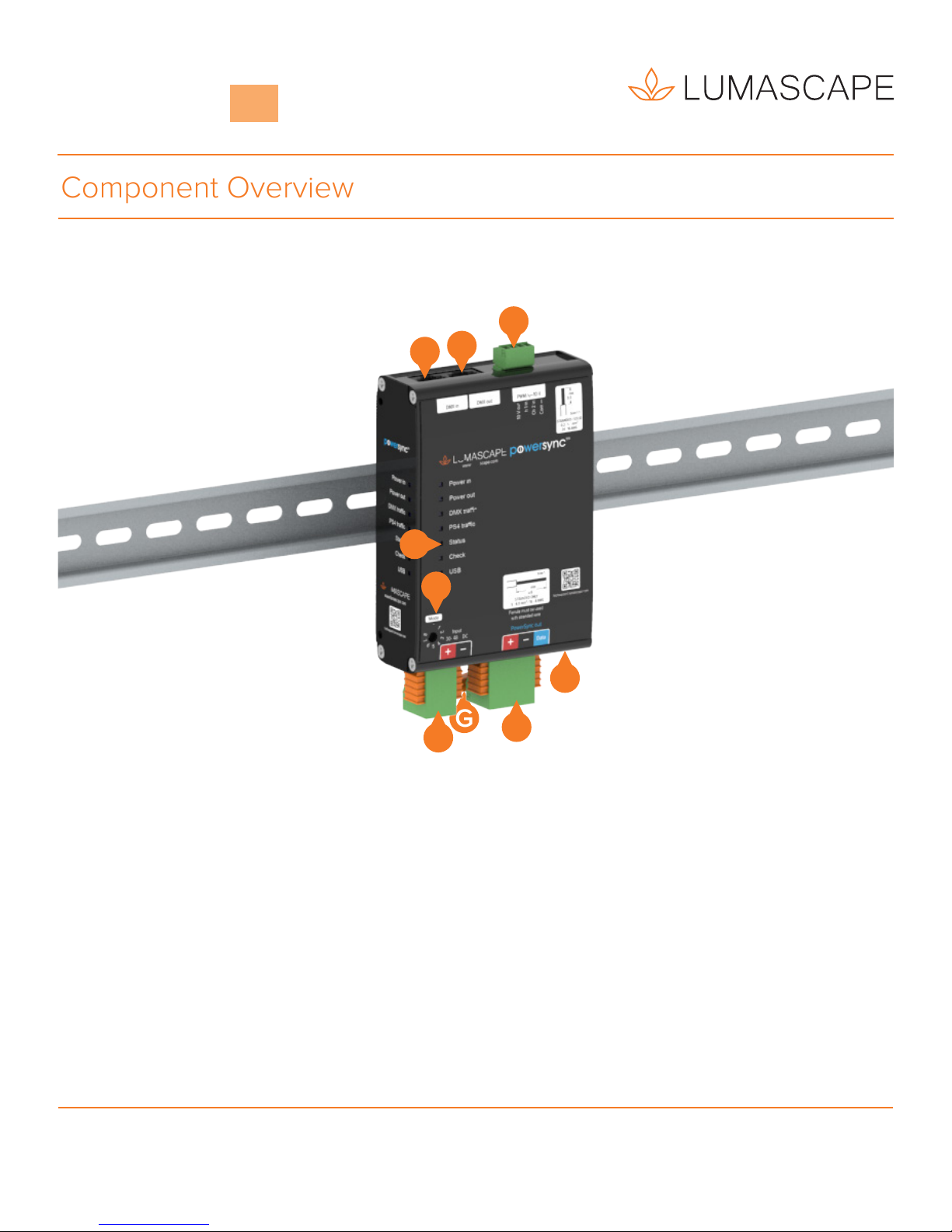
LOW VOLTAGE POWERSYNC
INTERFACE DIN RAIL MOUNT
LUMASCAPE ASIA PACIFIC Brisbane Technology Park, 18 Brandl Street, Eight Mile Plains, QLD 4113, Australia
Phone
+61
7
3854
5000
|
Fax
+61
7
3854
5001
|
Email:
[email protected] |
www.lumacape.comLUMASCAPE NORTH AMERICA 1300 Industrial Road, Unit #19, San Carlos, CA 94070, USA
Phone
+1
650
595
5862
|
Fax
+1
650
595
5820
|
Email:
[email protected] |
www.lumacape.comProducts and specifications are subject to change without notice.
USA I Australia I Asia I Middle East I Europe
1 / 12
IN0194 181128
PowerSync™
PS
LS6550
READ ALL SAFETY INSTRUCTIONS FIRST
› Follow instructions carefully, failure to do so could
damage equipment and will void warranty.
› Ensure installation complies with local law and
applicable standards.
› Input voltage is 30-48V DC maximum
› Only use Lumascape approved power supply, control
equipment and leader cables.
› Ensure mains input power is surge protected and power
filters are installed.
› Never make or break connections whilst the circuit is
energised.
› Do not make modifications or alter the product.
› Keep electrical connections clean and free from
moisture.
› Ensure components are in an appropriate, dry and dust
free operating environment.
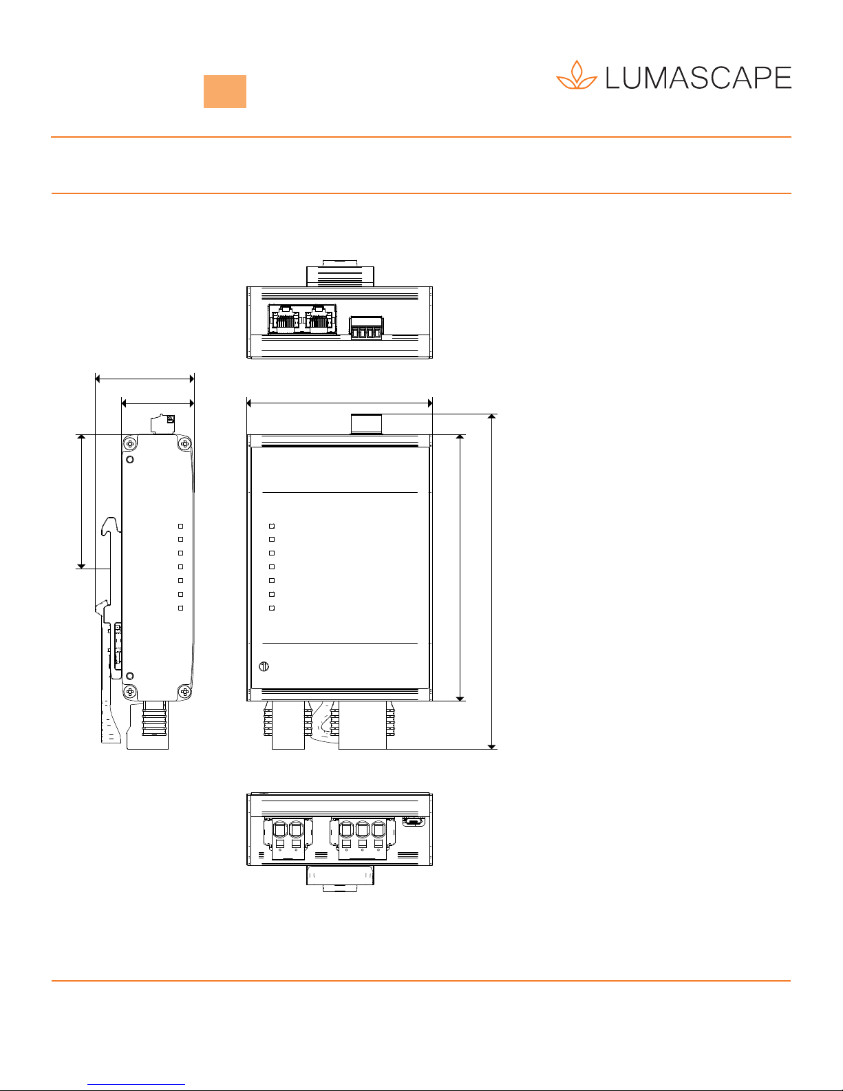
LS6550
Low Voltage PowerSync™
Interface DIN Rail Mount