Luminator BLACKCOMB LB4 Series User manual

BL
ACKCOMB
OWNER’S MANUAL
illuminating technologies for life
Operaon & Installaon Instrucons
NSF/ANSI Standard 55 Class A
C US
System Tested and Cered by
NSF Internaonal against CSA
B483.1 and NSF/ANSI 55
for Disinfecon Performance, Class A
System
Rated Flow
System
Rated Flow
LB6-02XA
1.6 gpm
LBH6-05XA
2.2 gpm
LB6-03XA
2.2 gpm
LBH6-10XA
4.1 gpm
LB6-06XA
3.4 gpm
LBH6-15XA
5.4 gpm
LB6-10XA
6.3 gpm
LBH6-25XA
7.9 gpm
LB6-15XA
7.9 gpm
LBH6-40XA
18 gpm
NSF/ANSI Standard 55 Class B
C US
System Tested and Cered by
NSF Internaonal against CSA
B483.1 and NSF/ANSI 55
for Disinfecon Performance, Class B
System
Rated Flow
System
Rated Flow
LB5-02XB
LB6-02XB
2.9 gpm
LBH5-05XB
LBH6-05XB
5.4 gpm
LB5-03XB
LB6-03XB
5.2 gpm
LBH5-10XB
LBH6-10XB
7.6 gpm
LB5-06XB
LB6-06XB
7.6 gpm
LBH5-15XB
LBH6-15XB
13 gpm
LB5-10XB
LB6-10XB
13 gpm
LBH5-25XB
LBH6-25XB
22 gpm
LB5-15XB
LB6-15XB
22 gpm
LBH5-40XB
LBH6-40XB
28 gpm
LUMINOR - Standard Systems
System
Rated
Flow
System
Rated
Flow
LB4-021
LB5-021
LB6-021
2
gpm
LBH4-051
LBH5-051
LBH6-051
5 gpm
LB4-031
LB5-031
LB6-031
3
gpm
LBH4-101
LBH5-101
LBH6-101
10
gpm
LB4-061
LB5-061
LB6-061
6
gpm
LBH4-151
LBH5-151
LBH6-151
15
gpm
LB4-101
LB5-101
LB6-101
11
gpm
LBH4-251
LBH5-251
LBH6-251
25
gpm
LB4-151
LB5-151
LB6-151
15
gpm
LBH4-401
LBH5-401
LBH6-401
40
gpm
LB4-201
LB5-201
LB6-201
21
gpm
LB4 Series LBH4 Series LB5 Series
LB6 Series
LBH5 Series
LBH6 Series

2|Page
Congratulaons on purchasing this ultraviolet disinfecon system. By purchasing a LUMINOR
UV Disinfecon system you are receiving not only a high quality product but also peace of
mind. Installing a UV system gives you reassurance that the water in your home will have an
extra level of protecon. This process is simple in its concept and eecve in its abilies to
disinfect your water. Simple maintenance and connuous disinfecon: LUMINOR makes it
that easy.

3|Page
TABLE OF CONTENTS
Safety Consideraons ......................................................................................................... 4
Before You Begin ................................................................................................................ 4
Water Quality Parameters .................................................................................................. 5
Assembly ............................................................................................................................ 6
System Sizing ...................................................................................................................... 8
Locaon .............................................................................................................................. 8
Installaon ......................................................................................................................... 9
System Disinfecon .......................................................................................................... 12
Cleaning the Quartz Sleeve .............................................................................................. 12
Cleaning the UV Sensor .................................................................................................... 13
Operaon ......................................................................................................................... 13
BLACKCOMB4.1 Controllers ..................................................................................... 14
BLACKCOMB5.1 & BLACKCOMB6.1 Controllers ......................................................... 14
BLACKCOMB5.1 & BLACKCOMB6.1 Power-up Sequence ........................................... 14
BLACKCOMB5.1 Operaonal Screens....................................................................... 15
BLACKCOMB6.1 Operaonal Screens....................................................................... 15
Lamp Countdown Sequence .................................................................................. 16
System Service Suggested ...................................................................................... 17
Lamp Replacement (BLACKCOMB4.1 systems) ........................................................ 17
Lamp Replacement (BLACKCOMB5.1 & BLACKCOMB6.1 systems) ............................ 17
QR Codes ............................................................................................................... 17
System Troubleshoong......................................................................................... 18
Temperature Management Devices ................................................................................. 20
Expansion Modules .......................................................................................................... 20
BLACKCOMB Standard Output System Specicaons ...................................................... 22
BLACKCOMB-HO High Output System Specicaons ....................................................... 23
Performance Data Sheet (on all NSF/ANSI Standard 55, Class A Systems) ....................... 24
Performance Data Sheet (on all NSF/ANSI Standard 55, Class B Systems) ....................... 25
Limited Warranty Statement: ........................................................................................... 26
Warranty Registraon ...................................................................................................... 27

4|Page
Safety Consideraons
It is important that care is taken when operang and/or maintaining your system.
1. Before servicing this equipment, disconnect the power cord from the electrical outlet.
2. Energy given o by the UV lamp is harmful to your eyes and skin. NEVER look directly
at an illuminated UV lamp without adequate eye protecon and always protect your skin
from direct exposure to the UV light.
3. For complete disinfecon, use ONLY genuine replacement parts.
4. Do not operate the unit if it has any damaged or missing components.
5. To avoid possible electrical shock, use only with a properly grounded electrical outlet.
6. Never perform any maintenance to the system unless you are comfortable in doing so.
Contact the manufacturer for service instrucons if required.
7. Do not use this system for any purpose other than what it was intended for. Misuse of this
system could potenally cause harm to the user or others.
8. Your system is intended to be installed indoors and away from leaking plumbing. DO NOT
plug the unit in if the system or any of the components are wet.
9. The disinfecon system should be directly installed into a ground fault circuit interrupter
(GFCI). If the use of an extension cord is required, the cord must be manufactured with a
minimum of 16 gauge wire and care should be taken to avoid potenal tripping hazards.
10. We recommend that a licensed plumber or cered technician install the system.
Before You Begin
The following will be needed for installing the UV system:
Tools
• Pipe cuer, hacksaw or other specialized tools required to cut into your exisng
plumbing (e.g. if you have PEX piping)
• Soldering tools (torch, ux, emery cloth and solder)
• Wrench (for ghtening ngs)
Other Materials
• Inlet/outlet connecons
• Teon™ tape

5|Page
Water Quality Parameters
UV disinfecon is only eecve if the UV light can pass through the water it needs to treat. This
means that the quality of your water is very important in order to ensure complete disinfecon.
Treated water should be tested for at the least the parameters listed below. If the water exceeds
the listed parameters LUMINOR strongly recommends that appropriate pretreatment equip-
ment be installed (equipment required will depend on parameters being treated):
Hardness: <7 gpg (120 mg/L) – if hardness level is 7 gpg or slightly below the
quartz sleeve must be cleaned periodically in order to ensure e-
cient UV penetraon; if above the water must be soened.
Iron (Fe): <0.3 ppm (0.3 mg/L)
Manganese (Mn): <0.05 ppm (0.05 mg/L)
Turbidity: < 1 NTU
Tannins (organics): <0.1 ppm (0.1 mg/L)
UVT (transmiance): >85% (Please contact LUMINOR if water has a UVT that is less than
80% for pre-treatment recommendaons)
You can have your water tested at a private analycal laboratory or by your local dealer. It is
always recommended to install pre-ltraon of at least 5 microns prior to a LUMINOR UV disin-
fecon system.

6|Page
Assembly
Unpack the system and ensure all the components are included with the system. Your system is
shipped with the following components:
BLACKCOMB (Standard output lamp systems)
CONTROLLER
GLOW PLUG
(BLACKCOMB5.1 units only)
UV SENSOR
(BLACKCOMB6.1 units only)
4.1 SYSTEMS
RC-B4.01
5.1/6.1 SYSTEMS
RC-B56.01
300016 Complete Assembly
310026 Teon Plug
310040 O-Ring
390007 Brass Nut
RS-B2.5 LB4/LB5/LB6 -06, -10, -15
series
RS-B3.5 LB4-20, LB5-20, LB6-20
series
RS-B2.5V NSF Class A series
GLAND NUT
O-RING
SLEEVE SPRING
QUARTZ SLEEVE
REACTOR
UV LAMP
320006
300038
RL-210- “-02” series
RL-290 “-03” series
RL-470 “-06” series
RL-820 “-10” series
RL-850 “-20” series
RL-999 “-15” series
310039
RQ-210 “-02” series
RQ-290 “-03” series
RQ-470 “-06” series
RQ-820 “-10” series
RQ-850 “-20” series
RQ-999 “-15” series
300083 “-02” series
300050 “-03” series
300052 “-06” series
300054 “-10” series
300061 “-15” series
300068 “-20” series
LAMP KEY

7|Page
BLACKCOMB-HO (High output lamp systems)
CONTROLLER
GLOW PLUG
(BLACKCOMB5.1 units only)
UV SENSOR
(BLACKCOMB6.1 units only)
GLAND NUT
O-RING
SLEEVE SPRING
QUARTZ SLEEVE
REACTOR
UV LAMP
4.1 SYSTEMS
RCHO-B4.12
(ts all units)
5.1/6.1 SYSTEMS
RCHO-B56.12
(ts all units)
POWER CORD
300016 Complete Assembly
310026 Teon Plug
310040 O-Ring
390007 Brass Nut
RSHO-B3.5 Standard series
RSHO-B3.5V NSF Class A series
260004 North American
260005 Euro
260006 Australian/New Zealand
260008 Brish
320006
300038
RL-210HO “-05” series
RL-330HO “-10” series
RL-420HO “-15” series
RL-600HO “-25” series
RL-950HO “-40” series
310039
RQ-210 “-05” series
RQ-330 “-10” series
RQ-420 “-15” series
RQ-600 “-25” series
RQ-950 “-40” series
300062 “-05” series
300063 “-10” series
300064 “-15” series
300007 “-25” series
300009 “-40” series
LAMP KEY

8|Page
System Sizing
All LUMINOR UV systems are rated for a specic ow rate in water that meets the quality param-
eters on page 5. PLEASE NOTE that increasing the ow above this rang or disinfecng water
that does not meet the quality parameters will decrease the dose and therefore compromise the
ecacy of the system.
If you need to determine your maximum ow rate, you can ll a 1 gallon bucket with water and
me how long it takes to ll up. It is always beer to oversize your system then to undersize. For
example, if your pump delivers 8 gpm it is recommended to install any of the BLACKCOMB 10
gpm systems.
Locaon
For Point of Entry (POE) systems, choose a locaon where the main cold water line is accessible.
The system must be installed aer other water treatment equipment (soener or lters), but
before any branches (See Figure 1). For Point of Use (POU) systems, install the unit just before
the faucet. LUMINOR recommends that a 5 micron lter be installed before the UV system for a
nal polishing step before the water is disinfected.
Solenoid
module
OPTIONAL COMPONENT
BY-PASS ASSEMBLY
*
SEDIMENT
FILTER
CARBON
FILTER
WATER
METER
WATER SOFTENER
TO DRAIN
BY-PASS
ASSEMBLY
SOLENOID
VALVE
CONTROLLER
TO HOT AND COLD WATER PIPES
SOLENOID
MODULE
*
*
*
*
*
*
*
Figure 1. Recommended POE Installaon Locaon
To facilitate lamp removal, ensure there is enough space at the lamp connector end to safely
remove the UV lamp and/or quartz sleeve (See Figure 2).
The controller will require a ground fault circuit interrupter (GFCI or GFI) outlet and should be
mounted beside or above the reactor.
PLEASE NOTE: All LUMINOR UV disinfecon systems are intended for indoor use only as they
should not be exposed to the elements.

9|Page
Installaon
Step 1: The reactor can be installed either horizontally or
vercally using the clamps provided. Vercal installaon is
the preferred method with the inlet at the boom (lamp
connecon at the top) as it allows any air that may be in the
lines to be easily purged from the system.
Step 2: The use of a by-pass assembly is recommended as
it will allow you to isolate the UV reactor. This will allow for
easier access in case maintenance is required (See Figure 3).
Step 3: Use the supplied fasteners to mount the UV reac-
tor to wood or drywall. If mounng to an alternate material
you will need to purchase the proper corresponding fasten-
ers.
Step 4: For water supplies where the maximum ow rate
is unknown, a ow restrictor is recommended so that the
rated ow of your parcular BLACKCOMB system is not ex-
ceeded. The ow restrictor should be installed on the inlet
port of the reactor.
Step 5: It is recommended to have a licensed plumber
connect the UV reactor to the water supply and may be a
requirement depending on where you are located.
Figure 3. By-pass assembly
Note: Installaon of your BLACKCOMB disinfecon systems shall
comply with applicable provincial/state & local regulaons.
Figure 2. Lamp Removal
Spacing
leave at least
an addional
reactor length
to facilitate
lamp and
sleeve removal

10|Page
Step 6: Once the system has been plumbed in, gently remove the
quartz sleeve from its packaging being careful not to touch the length
with your hands. The use of coon gloves is recommended for this
procedure as oils from the hands can leave residue on the sleeve and
lamp which can ulmately block the UV light from geng to the wa-
te r.
Carefully slide the sleeve into the reactor unl you can feel it hit the
opposite end of the reactor. Align the sleeve so it centered along the
length of the reactor, then gently push it in to lock it into the inter-
nal centering springs in the far side of the reactor. CAUTION: Pushing
too hard when the sleeve is not aligned can damage the centering
springs. Slide the o-ring onto the sleeve unl it is bued up against
the reactor.
Figure 4. Quartz
Sleeve Installaon
Step 7: Hand ghten the provided gland nut over the quartz sleeve onto the threaded end
of the reactor. It has a posive stop to prevent over-ghtening. A rm force may be required to
fully ghten the gland nut, but DO NOT USE TOOLS for this step. Insert the provided stainless
steel compression spring into the quartz sleeve. The spring works with the lamp and LUMI-Loc™
connector to create the proper lamp alignment. PLEASE NOTE: DO NOT install a UV lamp inside
the quartz sleeve without the sleeve spring in place.
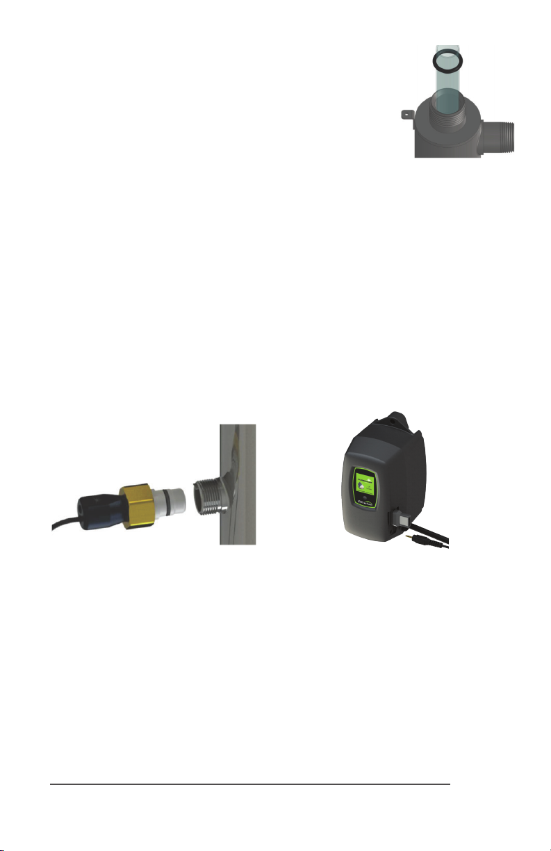
Step 8: Install the UV sensor (BLACKCOMB6.1 systems only). Align the at poron so it faces
the gland nut end and matches up with the half metal lip on the sensor port (see Figure 5). Insert
the sensor so it is fully seated and hand ghten the sensor nut.
Figure 5. UV Sensor Installaon Figure 6. IEP Connecon
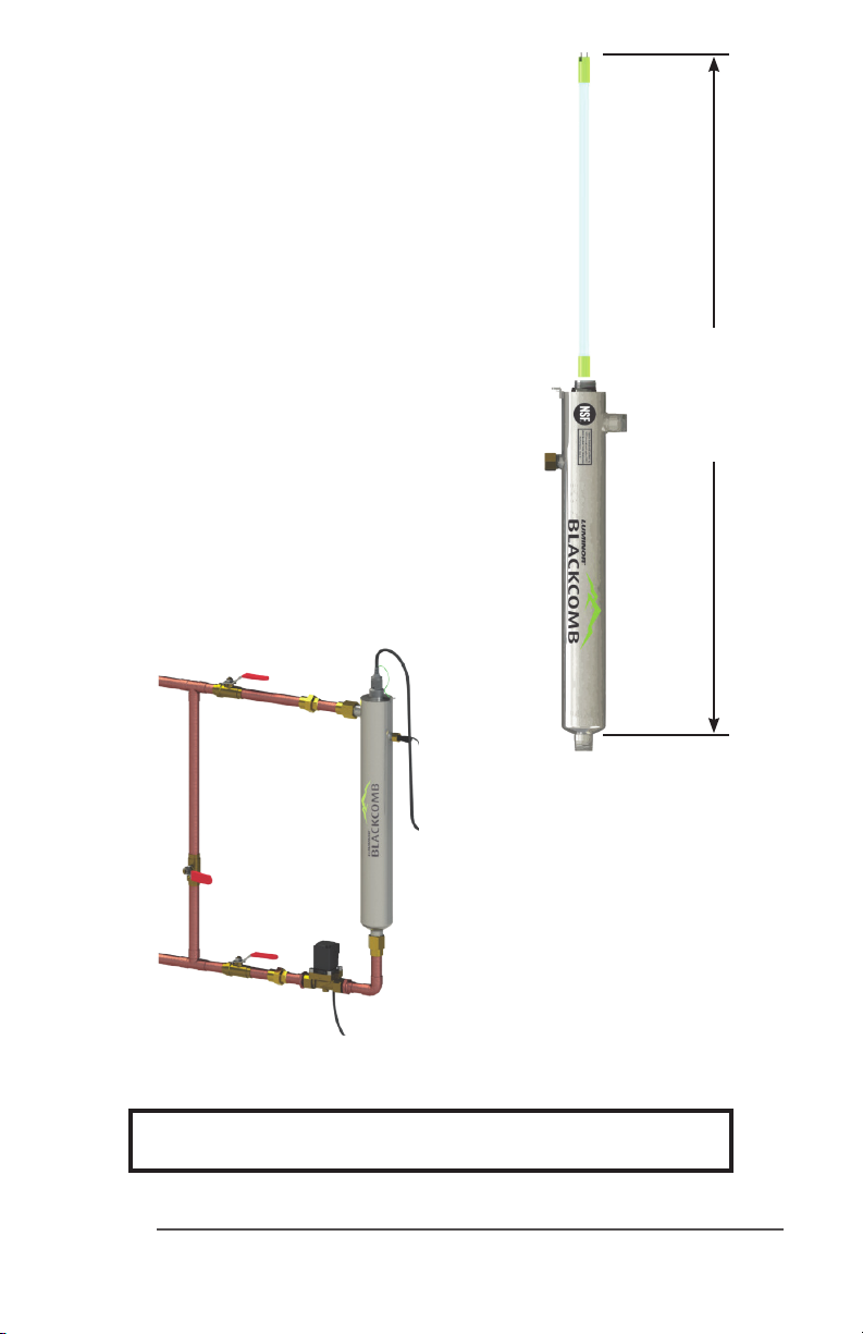
Step 9: The reactor is now ready for water ow. When all plumbing connecons have been
completed, slowly turn on the water supply and check for leaks. Make sure the by-pass valves are
funconing properly and that the water is owing through the reactor. The most common leak
is from the o-ring not making a proper seal on the reactor. For new installaons, review steps 6
and 7. For older systems drain the reactor, remove the o-ring, dry it and reapply silicon grease.
Reinstall the o-ring ensuring that it is properly sealed against the reactor and check again for
leaks.
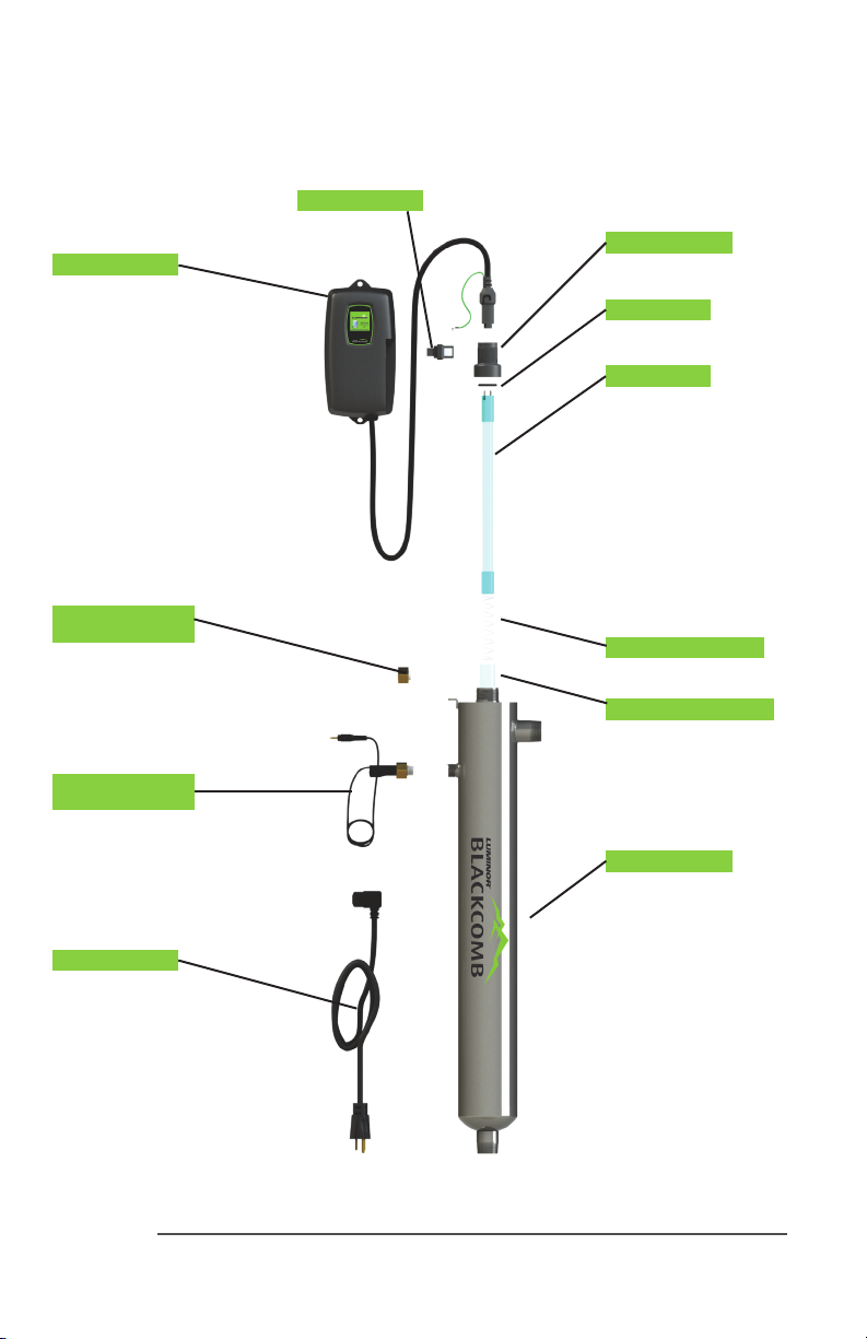
Step 10: Mount the controller to the wall so it is above or beside the reactor to ensure that no
moisture can deposit on any of the connecons (see Figure 1). Always mount the controller ver-
cally. For monitored systems, insert the sensor connector into the IEP port located on the right
side of the controller (Figure 6). For the sensor to be recognized by the controller, the controller
power must be plugged in last. Do not plug the controller power cord in before the last step.

11|Page
Step 11: Always hold UV lamps by their ceramic ends, not by the lamp quartz. Remove the lamp
from its packaging. Again, the use of coon gloves is recommended. Remove the lamp key from
the lamp’s connector and set it aside for the next step. Be careful to not touch the key’s exposed
contacts. Insert the UV lamp into the reactor, being careful not to drop it.
Step 12: Install the lamp key into the controller (BLACKCOMB5.1, BLACKCOMB6.1 systems only).
The key always comes packaged with the lamp and sits on the connector. With the key removed
from the lamp, orient it so the label is upright and facing you. The key will plug into the lamp key
port on the right side of the controller (Figure 8).
Step 13: Plug the LUMI-Loc™ lamp connector into the lamp. Note the keying for proper align-
ment (see Figure 7a, 7b). Insert the lamp connector into the gland nut and turn the connector
approximately ¼ turn to lock the connector to the gland nut as in Figure 9.
Figure 8. Lamp Key Installaon Figure 9. LUMI-Loc™ Connector
Step 14: Tighten the capve ground screw to the ground lug on the UV reactor to ensure proper
grounding.
Figure 10. Ground Screw Connecon
Step 15: Your system is now ready to be plugged into the appropriate GFCI protected outlet.
Refer to the following secon before any water is allowed to ow through the system.
Figure 7a. Standard Output UV
Lamp Connecon
Figure 7b. High Output UV
Lamp Connecon

12|Page
System Disinfecon
With a new installaon, or any me the UV system is shut down for service, without power, or is
inoperave for any other reason, the lines in the home or facility could be contaminated. Use the
following steps to fully disinfect the lines throughout the enre home or facility.
Step 1: Check for and remove any “dead ends” in the lines throughout the home as these can
harbor bacteria. Plug in the UV system and wait unl it is ready for operaon.
Step 2: Remove the lter cartridge from the last sump and ll it with 1-2 cups of household
bleach (most are 5.25% chlorine). Replace the sump and slowly turn on the water supply.
Step 3: At a water outlet, run the water unl bleach can be smelled. Repeat this for all faucets,
toilets, shower heads, refrigerators, outdoor taps, the washing machine, dishwasher, etc. at the
home or facility. Once nished, wait a minimum of 30 minutes before connuing.
Step 4: Reinstall the lter cartridge into the sump and ush the chlorine soluon by opening
all faucets unl chlorine can no longer be detected. Your home has now been disinfected and
your BLACKCOMB UV system is ready to use.
Cleaning the Quartz Sleeve
Depending on the water quality, the quartz sleeve may require periodic cleaning. At a minimum,
the quartz sleeve should be cleaned on an annual basis. The following steps outline a basic clean-
ing procedure.
Step 1: If a by-pass assembly is installed, shut the inlet valve o to prevent water ow through
the system. Otherwise, turn o main water inlet valve (and/or turn o the water pump).
Step 2: Disconnect power cord of UV system from electrical outlet.
Step 3: Release water pressure by opening a downstream faucet and then close the outlet
shut-o valve (if any). If there is no outlet shut-o valve, expect water to drain from the system
as the head pressure in the system will cause the water to ow back down.
Step 4: Remove the capve ground screw from the ground lug on the UV reactor.
Step 5: Remove the lamp connector from the reactor (gland nut) by pushing the LUMI-loc
connector in and turning it ¼ turn counter-clockwise. Disconnect the lamp connector from the
lamp. CAUTION: the lamp may be hot!
Step 6: Being careful to touch only the ceramic ends, remove the lamp out of the reactor.
Step 7: Unscrew the gland nut from the reactor exposing the end of the quartz sleeve.
Step 8: Remove the quartz sleeve and o-ring by gently twisng and pulling the quartz sleeve.
Step 9: Using a so, lint-free cloth or towel wipe the sleeve down using a commercial scale
cleaner (i.e. CLR® or LIME-A-WAY®). This removes scaling or iron deposits that may be on the
outside of the quartz sleeve. Be careful not to get any moisture or liquids inside of the sleeve.

13|Page
Step 10: Dry the sleeve with separate cloth.
Step 11: Replace the o-ring and slide the sleeve back into the reactor following steps 7 and 8
from the installaon secon of the manual.
Cleaning the UV Sensor
Depending on the water quality, the UV sensor may require periodic cleaning. At a minimum,
the UV sensor should be cleaning on an annual basis. The following steps outline a basic clean-
ing procedure.
Step 1: If a by-pass assembly is installed, shut the inlet valve o to prevent water ow through
the system. Otherwise, turn o main water inlet valve (and/or turn o the water pump).
Step 2: Disconnect power cord of UV system from electrical outlet.
Step 3: Release water pressure by opening a downstream faucet and then close the outlet
shut-o valve (if any). If there is no outlet shut-o valve, expect water to drain from the system
as the head pressure in the system will cause the water to ow back down.
Step 4: Place something under the reactor to catch any water that may come out of the reac-
tor during the removal of the UV sensor.
Step 5: Unscrew (counterclockwise) sensor nut from the reactor and pull the sensor slowly out
of the sensor port.
Step 6: Holding the sensor in your hand wipe the at poron (sensor face) of the sensor with
isopropyl alcohol using a clean lint-free cloth.
Step 7: Replace sensor following step 9 from the installaon secon of the manual.
Operaon
BLACKCOMB systems come with a feature laden controller that incorporates both the lamp driv-
er (ballast) and control features in one water-ght case. Four main controllers are available for
the BLACKCOMB systems (depending on your model). All four models feature a power factor
corrected, constant current lamp driver with a universal power input.
Please Note: While the LED or display screen is red and the buzzer is sounding the water from
the system should NOT be consumed. If any water does pass through the system during this
period, please follow the disinfecon procedure as outlined in this manual before the water
is consumed. For BLACKCOMB4.1 and BLACKCOMB5.1 systems, even though they have a visual
and audible warning built into the controller, a green LED or status screen does not necessarily
indicate that the water coming from this system is in fact potable (safe to drink). These systems
do not measure the level of disinfecon; they simply measure the “on-o” status of the lamp.
Please have your water checked for microbiological contaminants on a regular basis.

14|Page
BLACKCOMB4.1 Controllers
LB4
Series
LBH4
Series
Simplisc in operaon, these systems feature a tri-colour
LED that indicang system status and a 4-digit display to in-
dicate lamp life remaining. Pressing the buon will change
the display to indicate total running me. When the UV lamp
is on and within its operang age, the LED will be green.
When the UV lamp is not on or the lamp life has expired,
the LED will be illuminated red and an audible buzzer will be
sounding. To remedy this condion, the UV lamp must be
replaced with a new genuine LUMINOR UV lamp.
BLACKCOMB5.1 & BLACKCOMB6.1 Controllers
LB5 / LB6
Series
LBH5 / LBH6
Series
A full colour LCD screen provides the user with a detailed
descripon of the system’s performance in addion to pro-
viding any applicable fault messages and system diagnoscs.
The controllers used in both the BLACKCOMB5.1 and BLACK-
COMB6.1 are idencal. The dierence is that the BLACK-
COMB6.1 series of products includes a UV intensity monitor.
All BLACKCOMB5.1 and BLACKCOMB6.1 controllers include an
“innite expandability port” located on the right side of the
controller. Simply plug in an oponal UV sensor module into
the expandability port of a BLACKCOMB5.1 controller and the
system will now monitor the UV intensity of the system!
BLACKCOMB5.1 & BLACKCOMB6.1 Power-up Sequence
On start up, the controller will run through a diagnosc start-up and the sequence will be dis-
played as follows on the colour LCD:
Next, the controller checks for and inializes any oponal modules that may be aached to the
system.
Oponal Modules Check
- UV Sensor
- Solenoid
- 4-20 mA
- WIFI
- Remote Alarm
- Flow Meter
OR

15|Page
A nal module screen is displayed showing which specic modules were inialized.
The controller then displays the lamp opmizaon screen for 60 seconds to allow the lamp to
reach its opmum output. Finally, a nal “start-up complete” screen is displayed. The system will
now be ready to disinfect water ow.
all detected modules lamp reaching max output successful start-up
BLACKCOMB5.1 Operaonal Screens
On systems without the UV monitor, the default screen shows the LUMINOR Home Screen. At
any point during operaon the user is able to scroll through the LUMINOR Home Screen, Lamp
life remaining, QR Code, Contact Info and Maintenance Parts screens by pressing the buon
located on the front of the controller.
BLACKCOMB6.1 Operaonal Screens
On systems with the UV monitor, the system will display the same screens as on the BLACK-
COMB5.1 except the UV Intensity replaces the home screen. The UV Intensity screen displays
the level of UV light detected by the sensor. UV intensity can be aected by poor water quality,
scaling on the quartz sleeve and/or sensor, lamp failure or lamp expiring. The following screens
show the UV Intensity dropping.
Below 56%, the numbers and warning sign turn red and an audible chirp is given by the ballast
every 15 seconds. Below 51%, the screen is solid red and a constant audible alarm is given. This
alternates with a screen indicang “water may be unsafe for consumpon”. With the solenoid
module, the controller de-acvates the solenoid valve, shung o all water ow.

16|Page
audible chirp every
15 seconds
audible chirp every
15 seconds
constant audible
alarm
cycles with red low
UV screen
Lamp Countdown Sequence
The system counts down the number of days unl a lamp change is required.
BLACKCOMB6.1
BLACKCOMB5.1
BLACKCOMB4.1
At thirty days remaining, the LED or display screen will change to a yellow cauon indicator. At
seven days remaining, the system will addionally repeat an audible chirp. Past the zero day
threshold, the LED or display screen changes to solid red with a connuous buzzer.
BLACKCOMB6.1
BLACKCOMB5.1
BLACKCOMB4.1
At any point during this sequence, the audible chirp or alarm can be deferred for seven days
by holding the controller buon down for a period of ve seconds. The number of deferrals
used will be displayed as below. Once the deferral expires, the alarm will sound once again. The
deferral can be repeated up to three mes. PLEASE NOTE: At any point aer lamp expiraon,
the water may be unsafe for consumpon and should not be consumed without another form
of disinfecon.

17|Page
System Service Suggested
BLACKCOMB 5.1 & 6.1 controllers will display the System Service Suggested
Screen every 6 months to remind consumers to maintain both their UV and
other preltraon. This will serve as a prompt only and will not put the
system into alarm. To clear this condion simply press the buon located
below the screen.
Lamp Replacement (BLACKCOMB4.1 systems)
Aer the lamp is expired, it must be replaced with the same part number as indicated by the
label on the reactor. Begin replacing the lamp by unplugging the power for the controller, then
refer to Installaon, starng with step 11 (page 11) for instrucons on installing the new lamp.
To reset the mer in the controller, rmly hold down the buon on the controller for 10 seconds.
The controller will read “rSt3”, “rSt2”, “rSt1” and then beep. The buon can now be released, the
lamp countdown mer has been reset.
Lamp Replacement (BLACKCOMB5.1 & BLACKCOMB6.1 systems)
Aer the lamp is expired, it must be replaced with the same part number as indicated on the
Maintenance Parts screen or on the label on the reactor. With the system powered down,
remove and discard the lamp key from the controller. The replacement lamp is packaged with a
lamp key on the connector at the end of the lamp. Remove the key from the lamp and place it in
the controller. Refer to Installaon, starng with step 11 (page 11) for instrucons on installing
the new lamp.
QR Codes
A QR code (Quick Response code) is a matrix barcode rst designed for the
automove industry. LUMINOR uses the QR code to store a link to a specic
page on our website. Users with a camera phone equipped with the correct
reader applicaon can scan the image of the QR code and over a wireless
network connect to a LUMINOR web page in the phone’s browser. LUMINOR’s
QR webpage has informaon on how to purchase replacement components
as well as a helpful video directory on system servicing (i.e. How to change
a UV lamp or quartz sleeve). To access the QR code on the BLACKCOMB
controller, press the control buon unl the QR code screen appears.

18|Page
System Troubleshoong
Hard Alarms: The following give a constant audible alarm. If present, the solenoid valve is closed,
and the 4-20, remote alarm and wi modules transmit the alarm.
System Display Problem Resoluon
The system has detected
a problem with the
lamp.
Reset lamp protecon circuit
-unplug unit for 10 seconds.
Replace the lamp with the
part as indicated on the
silver label on the reactor or
on the Maintenance parts
screen.
Although the lamp is
powered and visibly
illuminated, due to the
lamp’s age its UV output
is no longer sucient for
proper disinfecon.
Replace the lamp with the
part as indicated on the
silver label on the reactor or
on the Maintenance parts
screen.
Low UV Intensity.
Remove and clean the
quartz sleeve and sensor.
Check water quality meets
requirements on page 5 and
add ltraon as required.
Replace lamp.
Wrong lamp or sensor
installed.
Replace component with
proper model as indicated.
The UV sensor is no
longer communicang
with the system.
Ensure all modules are
connected properly to the
system and to each other.
Modules can be tested
individually by plugging in
one at a me and cycling
power to the system.
Replace any module that is
not detected when plugged
directly into the controller.
A bad connecon has
been detected in the IEP
port.
Missing or incorrect
lamp key.
Ensure the lamp key
(packed with the lamp, on
the connector) is installed.
Unplug and reinstall the key.
Ensure the key part number
matches Lamp on Mainte-
nance Parts screen.

19|Page
So Alarms: The following remaining errors give a 15 second audible chirp only
System Display Problem Resoluon
The module
indicated is no longer
communicang to with
the system.
Ensure all modules are
connected properly to the
system and to each other.
Modules can be tested
individually by plugging in
one at a me and cycling
power to the system.
Replace any module that is
not detected when plugged
directly into the controller.
Refer to ow meter manual for detailed
troubleshoong
Warning: Aer any hard alarm, the home or facility should be disinfected. Follow the steps
under the “System Disinfecon” heading.
Boil Water Advisory: If any failure occurs on a BLACKCOMB UV system, the
water must not be used for human consumpon unl the system is returned to
a safe operaonal mode. If the water is used for human consumpon during this
period, the water must be boiled (minimum 20 minutes at a full boil) prior to
consumpon.

20|Page
Temperature Management Devices
Your LUMINOR BLACKCOMB system is designed to run connuously to ensure opmal
disinfecon. However, during periods when no water is drawn through the system, the energy
from the disinfecon process can cause the temperature of the water inside the chamber to rise.
In extreme situaons elevated water temperature or the uctuaon in temperature can lower
the output of the UV lamp. In these cases, or if the elevated water temperature is a nuisance,
LUMINOR recommends one of the following forms of temperature management devices.
Cooling Fan
Designed for use on the BLACKCOMB-HO systems, the “LUMI-coolTM” fan runs
connuously to cool the water by forced convecon. The long-life fan is powered
independently using a compact modular power adapter that operates from 90-
265V (47-63Hz). Order PN 130014.
Temperature Relief Valve (TRV)
On reaching a higher temperature, the TRV is designed to drain a small amount
of water to allow fresh, cooler water to enter the system. The TRV works without
power and comes complete with 10’ of drain line. Order PN 130031 for 1/2”
ports, PN 130032 for 3/4” ports, PN 130033 for 1” ports and PN 130034 for
1 1/2” ports.
Expansion Modules
BLACKCOMB5.1 and BLACKCOMB6.1 controllers incorporate an “Innite Expandability Port” (IEP)
which allows for expansion to the UV sensor and all other modules. Each module (including the
sensor) comes with both a male and female connecon. Connect any device to the controller
and all subsequent devices are then connected into the female end of last device added in a
“daisy chain” conguraon.
The following oponal expansion modules are available for use on BLACKCOMB5.1 and BLACK-
COMB6.1 UV controllers. Contact your authorized distributor for purchasing informaon.
REMOTE ALARM CONNECTION MODULE: Allows
for a connecon to a remote device such as a buzzer,
light, alarm system, PLC, etc., via a pair of contacts.
In normal operaon the OK and COM contacts will
be connected, and in a fault condion (Low UV,
Lamp fail, Power Fail), the Fault and COM contacts
will be connected. Maximum contact rang is 30V /
1A (use 16-22 AWG). Order PN MOD-RAM.
This manual suits for next models
68
Table of contents
Other Luminator Industrial Equipment manuals