Lush Projects Vibrati Punk Console Manual

Page | 1
Vibrati Punk Console Build Instructions
To find out more about the Vibrati Punk Console or buy a kit go to:
lushprojects.com/vpc
Step 1 –Introduction
To build the kit you’ll need:
-Vibrati Punk Console Kit
-Solder
-Wire Cutters
-Soldering Iron
-PP3 9 Volt battery
-Wire stripper or sharp knife
If you don’t know how to solder, or want a refresher this cartoon book “Soldering Is Easy, And Here’s
How To Do It”(http://lushprojects.com/vpc/build/FullSolderComic_EN.pdf) by Mitch Altman, Andie
Nordgren and Jeff Keyzer is a great introduction. This book covers all the soldering skills you need to
build the Vibrati Punk Console. Take some time to read the book if you need an introduction to
soldering.

Page | 2
Step 2 –Mounting the Integrated Circuit Sockets
The Vibrati Punk Console is built around a single printed circuit board (PCB). All the components are
placed on one side of the circuit board (the “component side” or top). The component side has
labels showing where to place components. The components are soldered in place on the other side
of the board (the “track side” or bottom). The track side has the metal tracks or traces that connect
the components.
I like to build circuits up starting from the shortest components and working towards the tallest
ones. This means that when you place components on the board they don’t fall out easily when you
turn the board over to solder.
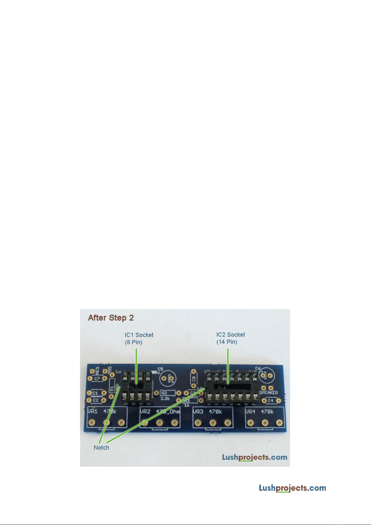
You’ll start building with the sockets that will contain the Integrated Circuits (or “ICs”) in the finished
project. You will have two different sockets one with 8 pins and one with 14 pins. The pins are
arranged in two parallel rows. At one end of each socket there is a notch in the plastic. This notch
shows the correct orientation of the socket. It is vital that you put the socket in the board the right
way round and that subsequently the ICs also go in the socket the right way round! We use sockets
because the ICs can be damaged by heat; therefore for beginners using sockets is a safer option.
Referring to the photos and the markings on the board take one of the sockets and insert it the right
way round from the component side of the board. Turn the board over and solder one corner pin
and then check that the socket is nice and level in the board. If not melt the solder on the pin and
push the socket in nicely. Now solder the diagonally opposite corner and check the socket is still
level. With only two corners soldered you should be able to level the socket by working alternately
on the two corners.
Now solder all the remaining pins. Take care not to bridge adjacent tracks when soldering. If you do
bridge tracks then use the “too much solder” advice from the “Soldering is Easy” booklet or try
desoldering if you have a desoldering tool.

Page | 3
Step 3 –Add Resistors
The Vibrati Punk Console uses four Variable Resistors to control the sounds, but at this stage we are
just going to add the fixed resistors. Fixed resistors are small cylindrical components with coloured
bands that indicate the value of their resistance. Resistors can go in to the circuit either way around.
Using the advice in the “Soldering Is Easy” booklet insert the three fixed resistors where shown on
the board. These are the colours you need to know:
Resistor
Value
Markings
R1
100k Ohm
Brown, Black, Yellow, Gold
R2
2.2k Ohm
Red, Red, Red, Gold
R3
1k Ohm
Brown, Black, Red, Gold

Page | 4
Step 4 –Add Small Capacitors
The Vibrati Punk Console uses 6 small capacitors. These are of a type called “Ceramic Discs” and look
like brown discs with leads coming off one side. This type of capacitor can go in the circuit either way
round. There are two different values of small capacitor in this circuit so make sure that you identify
the odd-one out and put it in position C3.
The small capacitors are:
Capacitor
Value
Markings
C1, C2, C4, C7 and C8
100nF
“100n” or “104”
C3
10nF
“10n” or “103”
Solder these 6 capacitors to the board.

Page | 5
Step 5 –Add Big Capacitors
The Vibrati Punk Console has 2 larger capacitors of a type called “Electrolytic”. These have a polarity,
a positive and a negative lead, and have to go in the circuit right way round. There are two ways to
determine the polarity of this type of capacitor. The negative lead is shorter than the positive lead.
Also one lead (normally the negative) is marked with an arrow on the side of the capacitor.
Identify the two capacitors as shown:
Capacitor
Value
Markings
C5
100µF
“100µF”
C6
10µF
“10µF”
Solder each of these capacitors in to the board with the correct polarity. On the board the positive
lead is shown with a “+” sign and a hollow bar. Insert the longer lead in to the hole marked with the
“+” sign.

Page | 6
Step 6 –Add the Variable Resistors
There are four variable resistors that control the sound of the Vibrati Punk Console. These are
soldered in a row on one edge of the circuit board so they can be mounted on a control panel if
desired. There are two different values of variable resistor. The value is labelled in text on the case.
Identify the resistors as shown:
Variable Resistor
Value
Markings
VR1, VR3 and VR4
470k Ohm
“470k” or “470kΩ”
VR2
470 Ohm
“470” or “470R” or “470Ω”
Put the variable resistors through from the component side of the board and solder the pins on the
back. The control shafts for the variable resistors should face away from the board. The knobs
provided will push-fit on to the variable resistor shafts.
Congratulations –you’ve now finished all the key components on the board. You now just need to
mount the speaker, battery connector and power switch which connect to the board externally.

Page | 7
Step 7 –Connect the Speaker
Cut the grey wire provided in half. These two lengths are used to connect the speaker. Strip about
5mm of insulation off each end of wires. You can strip the wire using a special wire stripping tool, or
by gently scoring the insulation with a sharp knife and pulling the end off. Once you’ve stripped the
wire twist the ends neatly.
Once you’ve stripped the insulation, solder one end of each wire to the tags provided on the back of
the speaker. Thread the stripped wire through the hole in the tag and fold the end of the wire over
to make a mechanical join. Apply solder in the same way you did for soldering components to the
circuit board.
Now attach the other ends of the wires to the circuit board. There are two holes labelled “SPEAKER”
at one end of the board where these wires connect. Thread the end of the wire through the board
from the component side so that the insulation rests on the board. Solder the wire in place like a
component lead.
NOTE: In situations where there are multiple speakers it is necessary to observe the polarity of the
speaker in order to get the correct sound. As we only have one speaker for this project the leads can
be connected either way round.

Page | 8
Step 8 –Connect the Battery Clip and Switch
To complete this step you will need the battery clip, red wire and switch. Take the battery clip and
solder the red wire from the clip to one tag on the switch (use the same technique as you did for
soldering to the speaker in Step 7). Conventionally in electronics red wiring is used to show the
positive voltage and black wiring is used to show the negative voltage.
Strip the ends of the red wire and solder one end to the other tag on the switch.
In the corner of the circuit board you will find two holes labelled “POS” and “NEG”. Connect the
other end of the red wire from the switch to the “POS” terminal and the end of the black wire
coming from the battery clip to the “NEG” terminal (use the same technique as soldering the
speaker leads to the circuit board in Step 7).
Battery Clip and Power Switch Wiring

Page | 9
Step 9 –Checking
Congratulations –you have now completed all the soldering on the Vibrati Punk Console. Now is a
good time to take a break and rest your eyes and hands for a moment.
I know you want to switch the Vibrati Punk Console on, but carefully checking the circuit now will
save a lot of problems later. Take a while to carefully check the circuit and fix any errors. Carefully
inspect all the components and connections. Things to particularly look for:
All connections neatly soldered and not accidently bridged on to adjacent solder points
Wiring to battery connector/switch and speaker corresponds to the diagrams
Large capacitors and Integrated Circuit (IC) sockets are round the right way
C3 is a different value to all the other small capacitors
VR2 is a different value to all the other variable resistors

Page | 10
Step 10 –Inserting the Integrated Circuits (ICs)
In this step we’ll take the two Integrated Circuits (ICs) and insert them in to the sockets on the
board. To get the ICs in to the sockets you’ll probably need to bend the pins so they are at right-
angles to the body. To do this use a pair of small pliers or carefully bend the pins against a flat
surface by holding the body and pressing the pins in to position.
Align the IC with the socket and make sure that the notch or dot at one end of the IC corresponds to
the notch in the socket. Make sure all the IC pins are over the slots in the socket. When everything is
in position, press the IC down firmly in to the socket. Check that all the pins are nicely in the socket.
Integrated Circuit
Type
Notes
IC1
NE555
8 Pin
IC2
NE556
14 Pin

Page | 11
Step 11 –Turning on and testing
Now is the big moment! Set the four variable resistors to approximately the middle of their range.
Set the switch to the “OFF” position (refer to the diagram in Step 8 to check the OFF position).
Connect a 9 Volt PP3 battery (not supplied in the kit) to the battery clip. Take a deep breath and
switch the circuit “ON”. If it makes a sound it’s working.
If things don’t work then DON’T PANIC. Here are some things to check.
Have you checked the power switch in both positions?
Have you put all the components in? In particular check the wiring to the battery and switch.
Make sure the variable resistors are around the middle. This is where the circuit works best.
Go back to Step 9 and double check everything. 99.9% of problems are caused by small
mistakes in wiring –eg solder bridges between connections or bad solder joints.
Are the ICs and large capacitors in the right way? If you put the ICs in backwards you may
have destroyed them :-( Replacement ICs are easy to obtain though :-)
Hopefully you are now the proud owner of a Vibrati Punk Console. Have fun.
Table of contents