BLACK NOISE COSMOS Manual

COSMOS
Build Instructions
V1.0

KIT CONTENTS
Thank you for purchasing
Cosmos DIY Kit.Cosmos is a
new kind of module that will
help you to creating complex
modulation, sounds, patterns
with ease and will lead you to
newsoundsterritories.
BEFORE ASSEMBLING YOUR
KIT, MAKE SURE YOU HAVE
ALLTHECOMPONENTS.
01-Faceplate
02-PCB Control Board
03-PCB Main Board
BAG A
A1-Jack Socket 26pcs
A2-Jack Nuts 26pcs
BAG B
B1-LED Dual R/G 12pcs
B2-LED Spacers 12pcs
B3-PinHeader 1x28 2pcs
B4-PinHeader M 1x2 2pcs
B5-PinHeader F 1x5 2pcs
B6-Power Cable 1pcs
WARRANTY
BLACKNOISEwarrantsthecontentsof
thiskit to be freeofdefectsinmaterials
orworkmanshipandtobeconformwith
the specifications at the time of
shipmentfora period oftwoyearsfrom
the date of purchase. We do not
warrant, and we do not repair or take in
modules to troubleshoot end-user DIY
build faults or second hand DIY
products.BLACKNOISE cannotbeheld
responsible for any damage caused by
oneofour DIYkitsandresultingfroman
end-userDIYbuildfaults.

FACEPLATE
A1
First we will prepare the
faceplate. The B4 connectors
must be surface soldered on
thebackoftheFaceplate.
To solder the connectors we
recommend using solder
paste.Ifyoudonothavesolder
past you can also use solder
wire.
If you use solder past place a
smallamountofpasteoneach
of the faceplate pins then
placetheconnectors.holdthe
connector perpendicular to
the faceplate using pliers and
solder one of the pins with a
soldering iron. When the first
pin has cooled, solder the
second pin then repeat these
steps for the second
connectors.
If you use soldering wire,
prepare a blop of tin on the tip
of your iron, hold the
connector perpendicular to
the faceplate with pliers and
solder the first pin of the
connector.When the first pin
has cooled, solder the second
pinthenrepeatthesestepsfor
thesecondconnectors.
Once the two connectors are
soldered clean the flux residue
with Isopropyl Alcohol and a
cleanbrush.

B1 CONTROL BOARD
The B5 connector must be cut to form two two-pin connectors
from a single B5 connector. The kit includes a 2nd B5 connector
incasethe1stconnectorisnotcut correctly.
To separate the single B5 connector into two separate
connectors, use a cutter and apply pressure on the end of pin 3
asshowninpictureA.Itisnotnecessarytoapplyalotofpressure
astheplasticoftheconnectorisquitesoft.Ifyouapplytoomuch
pressureyourisk breakingtheconnector.
Onceyouseeasmallnotchspotthesameoperationontheother
endofthepin as in picture B.Turn the connectoroverandrepeat
theoperationoneachendofpin3asin picture C.Onceeachend
of pin 3 has been cut, the connector should break along pin 3 to
form two connectors as in the picture D. If this is not the case,
repeat the previous operation applying a little more force for
eachcut.
Once you have two connectors of 2 pins each as in photo Dyou
canmoveontothenextstep.
If the connector does not separate neatly into two connectors,
use the 2nd B5 connector provided and repeat the previous
steps.

B2 CONTROL BOARD
In the kit you will find 12 LEDs
B1and12spacerLEDs B2.
Start by placing one LED
Spacer on each of the LEDs.
The spacers do not have any
particular orientation, just
make sure to pass each of the
LED legs into the holes of the
LEDSpacer.
Once the twelve LED spacers
are installed, you can move on
tothenextstep.

B3 CONTROL BOARD
Mount the PCB of the control board on a vice or a 3rd hand. You
can use the edge rails of the PCB to hold it as in picture A. Make
sureyouhavespaceunderthePCB fortheLEDlegstohang.
Start byplacingtheLEDs
PAYATTENTIONTOTHEPOLARITYOFTHELEDS.
LEDs have one leg shorter than the other called the cathode,
make sure to place the cathode in the square shaped hole as in
pictureB.ThenplacetheremainingLEDsasinpictureC.Onceall
theLEDsareplaced,gentlyturnyourPCBovertoensurethatthe
polarityofeachLED is respected.
OnceyouaresurethatalltheLEDsarecorrectlyinstalledyoucan
moveontothenextstep.

B4 CONTROL BOARD
Onceall theLEDsareinstalled,
install the 26 jack connectors
A1.
Once all the jack connectors
are installed, place the B5
connectors cut out in step B1.
See the picture to find the
locationoftheB5 connectors.
Once the jack connectors and
the B5 connectors are
installed, proceed to the next
step.

B5 CONTROL BOARD
Once the jack connectors and the B5 connectors are installed, you
canplacethefaceplate.
PAY ATTENTION TO THE ORIENTATION OF THE FACEPLATE. The
connector for the expander in picture Aindicates the top of the
module. When you place the faceplate make sure that the name of
the COSMOS module written at the top of the module match the
expander connector as in picture B.When placing the faceplate
makesurethattheB4pin-headerofthefaceplatesolderedinstepA1
isnestedwiththeB5connectorinstalledinstepB4
Once you have made sure that the faceplate is correctly installed,
screwthe26A2nutsontoeachofthejackconnectors.
When all the nuts have been screwed, turn the PCB over and solder
the components starting with the jack connectors, then the B5
connectors and finally the LEDs. Before soldering each component
make sure it is flush with the PCB.
Once all the components are soldered, make sure that there are no
solder bridges, cold solder joints or unsoldered pins. When you are
surethateachcomponenthasbeensolderedcorrectly, cut the LED
legsusingpliersasinpictureD.
Finally clean all flux residue with ispropol alcohol and a clean brush.
Youcanthenproceedtothenextstep.

You can now remove the edge
rails of the control board. Grab
one of the edge rails with a
pliers and bend it up then
down. the edge rails should
snapoff.
DO NOT PULL THEM OR
TWIST THEM, THE EDGE
RAILS ARE MADE TO BE
REMOVEDBYBENDING.
Once one of the edge rails has
been removed, repeat the
operation for the second edge
rail. Once both edge rails have
been removed you can move
ontothenextstep.
B6 CONTROL BOARD

C1 MAIN BOARD
You can now prepare the main board, first remove the two edge
railsasinstepB6.
OncetheedgerailsareremovedyoucansnaptheB3pin-header
onto the main board. Make sure to snap the longest part of the
pin-header into connector like on picture B. Once one of the
pin-headers is snapped, repeat the operation for the second
pin-header.
Once both pin-headers have been installed you can place the
controlboardon the pin-headers.
PAY ATTENTION TO THE ORIENTATION OF THE TWO BOARDS.
the module name COSMOS is on top of the main board, make
shuretoalign it with the COSMOS nameontopofthefaceplate.
Once both boards are correctly aligned, make sure that the
pin-header is flush with the control board and soldered each of
thepinsofbothpin-headers.

You can now test the
continuityofyourmodule.Use
a multimeter set to continuity
andconnectoneoftheprobes
tooneofthepinsin the center
of the power connector. With
theotherprobetouchthe+12V
pinsthen-12Vpinsateachend
of the connector. Your
multimetershouldnotring.
Onceyoumakesurethatthere
is not short circuit, you can
install the B6 power cable
includedinthekit.
ALWAYS USE THE PROVIDED
RIBBONTOPOWERCOSMOS
It has a specific header
orientation.Otherribbonwon’t
damage the module, but it will
not start. Don’t use the
provided ribbon to power
anothershrouded module.
Onceconnectedtoyourpower
supply you can proceed to the
nextstep.
C2 MAIN BOARD
-12V
+12V
GND

D1 CALIBRATION
FOR THE CALIBRATION OF COSMOS AN OSCILLOSCOPE WITH
AT LEAST TWO CHANNELS IS MANDATORY. Here we will use a
DATAfromMordax.
We will beginthecalibrationofyourCOSMOSwith theα section.
Send gates into input X of COSMOS and leave input Y
disconnected. To generate gates you can use the gate output of
a keyboard or sequencer. Here the gates are displayed on
channel 1 of the oscilloscope (green trace). Connect the gate
outputofsectionαintothe channel2inputofyouroscilloscope.
If the gate output of section αis always high like on picutre A,
turn the leftmost trimmer clockwise as in picture B until
channels 1 and 2 of the oscilloscope display the same gates.
Once the gates are the same on channel 1 and 2 turn 1 full turn
clockwise and section αis complete, you can now move on to
thenextstep.

D2 CALIBRATION
FOR THE CALIBRATION OF COSMOS AN OSCILLOSCOPE WITH
AT LEAST TWO CHANNELS IS MANDATORY. Here we will use a
DATAfromMordax.
To calibrate section βsend gates into input X of COSMOS and
sent a fixed voltage of +5V into the Y input. In this example
channel 1 (green trace) shows the gates sent into the X input,
channel 2 (blue trace) the fixed voltage sent into the Y input and
channel 3 (red trace) the gate output of the section β.if your
oscilloscope only has 2 channels, make sure you send a fixed
voltage of +5V to the Y input, use channel 1 to monitor the gates
sent to the X input and use the second channel to monitor the
gateoutput.
Thegateoutput of section βmust output gatesasinpictureCif
this is not the case as in picture Aturn the second leftmost
trimmerclockwiseas inpicturephotoBuntilyouobtaingatesas
inimage C.Oncethegatesarethesameon channel 1 and 3 turn
1 full turn clockwise and section βis complete, you can now
moveontothenextstep.

D3 CALIBRATION
FOR THE CALIBRATION OF COSMOS AN OSCILLOSCOPE WITH
AT LEAST TWO CHANNELS IS MANDATORY. Here we will use a
DATAfromMordax.
To calibrate section γsend gates into input X of COSMOS and
sent a fixe voltage of +5V into the Y input. In this example channel
1 (green trace) shows the gates sent into the X input, channel 2
(blue trace) the fixed voltage sent into the Y input and channel 3
(red trace) the gate output of the section γ.if your oscilloscope
only has 2 channels, make sure you send a fixed voltage of +5V to
theYinput,usechannel1 tomonitorthegatessenttotheXinput
andusethesecondchanneltomonitorthegateoutput.
Thegateoutputof section γmust outputgatesasin picture Bif
thisisnotthecaseasinpictureAturnthetherightmosttrimmer
counterclockwise until you obtain gates as in image B. Once the
gates are the same on channel 1 and 3 turn 1 full turn
counterclockwiseandsectionβiscomplete.
You have finished calibrating your COSMOS and you can now
enjoyit, congratulations!
To learn more about your COSMOS and find dozens of patch
ideas, we advise you to consult the COSMOS user manual
availablefrom the resourcessection of our website.
COSMOS IS A FULLY ANALOG MODULE, IT IS POSSIBLE THAT
OVER TIME THE TRIMMERS WILL DETUNE AND THE MODULE
WILL NOT BE CORRECTLY CALIBRATED. IF THIS IS THE CASE,
FOLLOW THE SAME PROCEDURE TO RECALIBRATE YOUR
COSMOS.
Other manuals for COSMOS
1
Table of contents
Other BLACK NOISE Recording Equipment manuals
BLACK NOISE
BLACK NOISE SAM-C Manual
BLACK NOISE
BLACK NOISE QBI Manual

BLACK NOISE
BLACK NOISE DRII User manual

BLACK NOISE
BLACK NOISE GOMA Manual

BLACK NOISE
BLACK NOISE SAM-C User manual

BLACK NOISE
BLACK NOISE SALLEN KEY User manual

BLACK NOISE
BLACK NOISE EG-LFO II User manual

BLACK NOISE
BLACK NOISE MIXER4 User manual

BLACK NOISE
BLACK NOISE Dual Rectifier II - S User manual

BLACK NOISE
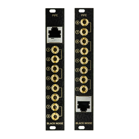
BLACK NOISE PIPE User manual