Dantel 00331 User manual

CAUTION
Install or remove modules from the shelf only when the power is off.
If you install a module in the shelf with the power on, the internal
circuitry may suffer damage and the product warranty will be void.
Remove and install circuit boards only in a static-safe environment
(use antistatic wrist straps, smocks, footwear, etc.).
Keep circuit boards in their antistatic bags when they are not in use.
Do not ship or store circuit boards near strong electrostatic, electromag-
netic, magnetic, or radioactive fields.
For more complete information on electrostatic discharge safety
precautions, refer to BellcoreTM Technical Reference #TR-NWT-000870.
Copyright 1998 by Dantel, Inc. • Dantel is a registered trademark of Dantel, Inc. • ISO 9001 Registered
Printed in the U.S.A.
INSTALLATION&OPERATION MANUAL
00331-0398<90-00044>
00331 DTSS3ON
ORDER WIRE/PABX
INTERFACE
About this Practice:
This practice has been reissued to:
• Replace Fig. 1.
Issue date: March 1998
Reissued Practices: Updated and
new content can be identified by a
banner in the right margin.
UPDATED
Table of Contents
Ordering Information ............................................................................ 2
General Description ............................................................................... 2
Circuit Description ................................................................................ 3
Installation ............................................................................................ 5
Operation ............................................................................................. 11
Technical Specifications....................................................................... 13
Warranty ............................................................................................. 14

PAGE 2 00331-0398<90-00044>
ORDERING INFORMATION
NOTE: This section lists the different options available for this product. To order any of the avail-
able options, contact Dantel Inside Sales through our toll-free number, 1-800-432-6835.
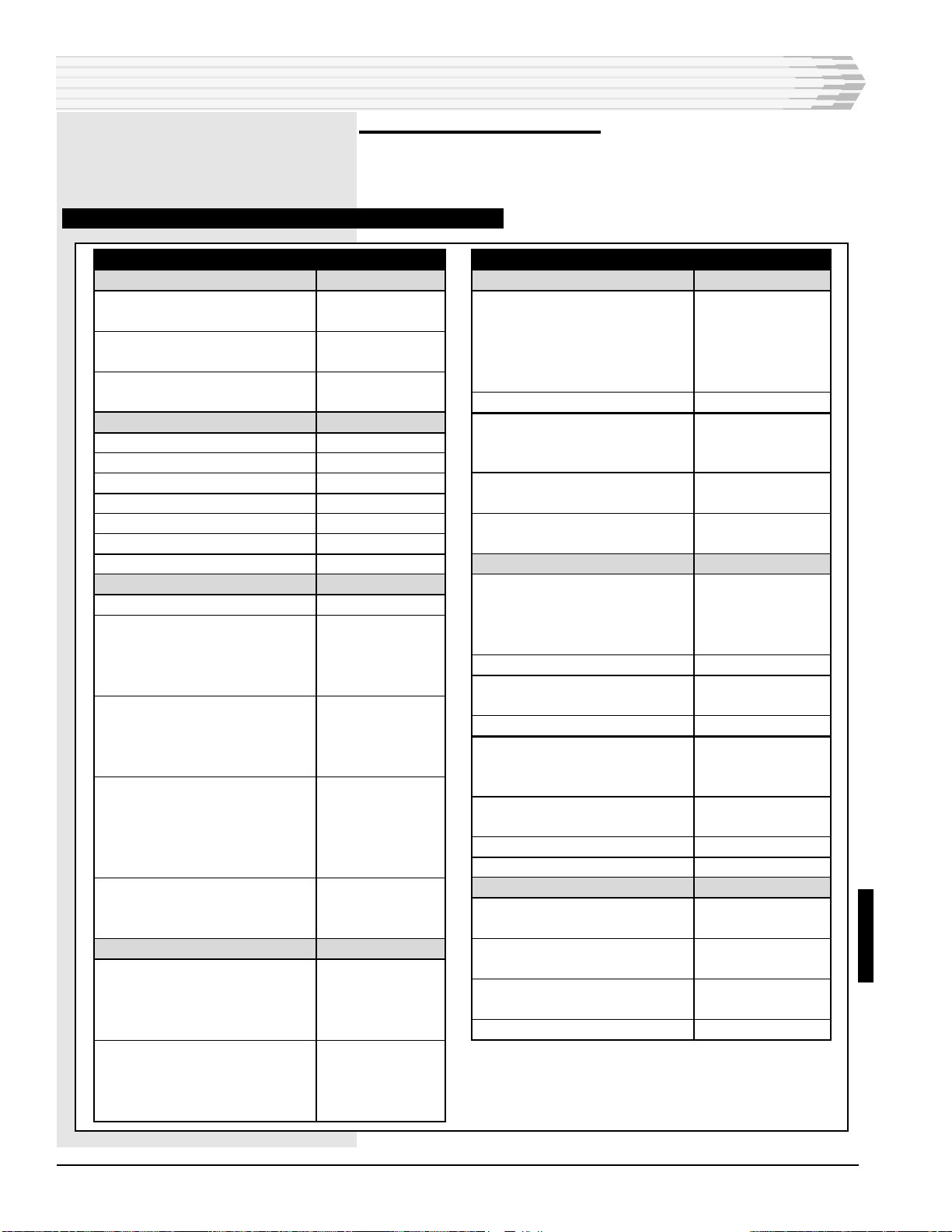
OPTION NUMBER FEATURES
B15-00331-00 Off-Net; 2-Wire Interface; 3-Digit Dialing
B15-00331-01 Off-Net; 4-Wire Interface; 3-Digit Dialing
A15-00331-05 Off-Net; 2-Wire Interface; 6-Digit Dialing
GENERAL DESCRIPTION
T
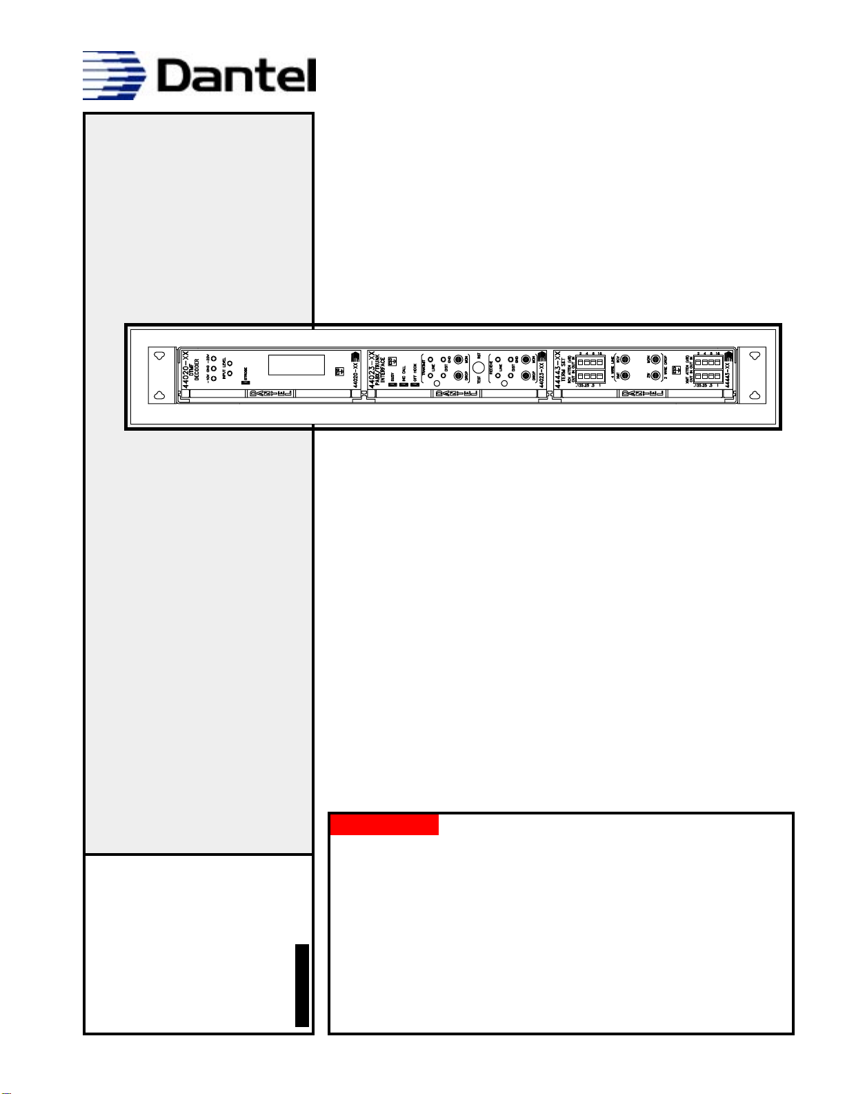
he Dantel 00331 DTSS3ON Order Wire/PABX Interface
(00331 Interface) lets any station in an order wire system
dial an access line directly to a central office or through a PABX.
The 00331 Interface can then dial out through the Public
Switched Telephone Network (PSTN). Alternately, an outside
party can dial into the order wire system and selectively dial any
desired station.
The DTSS3ON can be added to any existing order wire system
using the DTSS3A Selective Signaling Order Wire terminals.
The off-net package does not have to be at the same place as a
station package. The modules provide complete level coordinat-
ing circuits, including switchable pads on the Term Set front
panel.
Three versions of the DTSS3ON are available:
♦The B15-00331-00 unit is equipped with a term set for inter-
facing two-wire lines. It will work with either ground-start or
loop-start systems, with or without wink off.
♦The B15-00331-01 unit does not have the term set, and is
used only for interfacing four-wire E and M trunks. Both the
-00 and the -01 options feature 3-digit dialing.
♦The A15-00331-05 unit is equipped for interfacing two-wire
lines just as the -00 option; however, offers 6-digit station
address decoding.
Since the DTSS3A system does not utilize automatic privacy, the
off-net package provides a tone which announces that an off-net
caller has connected to the system.

00331-0398<90-00044> PAGE 3
The off-net package provides forced disconnect, which allows order
wire users to disconnect an unwanted call from the outside by
dialing # or * and three digits. If the unwanted caller tries to
call again, the DTSS3ON will not answer. Normal operation is
restored by pressing the # or * key again.
The 00331 Interface has three 400-type plug-in modules. The
modules include:
♦The 44443 Term Set
♦The 44023 PABX/Trunk Interface
♦The 44020 DTMF Decoder (with 49018 subassembly for
3-digit dialing or 49028 subassembly for 6-digit dialing).
The modules install into a 41071 mounting, which places the
three modules horizontally in 1 3/4 inches of rack space.
The 00331 Interface operates on -21 to -56 VDC power.
NOTE: The modules used in the DTSS3ON are registered under part
68, FCC rules. The Federal Communications Commission
requires certain precautions and procedures be followed when
connecting the DTSS3ON to the Public Switched Telephone
Network. Refer to the 44023 and 44443 module practices for
details and for the device registration numbers.
GENERAL DESCRIPTION
CIRCUIT DESCRIPTION
F
ig. 1 shows a 00331 DTSS3ON Order Wire/PABX Interface
block diagram. Functional schematics and circuit descrip-
tions of individual modules contained in the 00331 DTSS3ON
are located in the practices specific to those modules.

PAGE 4 00331-0398<90-00044>
FIG. 1 - 00331 DTSS3ON FUNCTIONAL BLOCK DIAGRAM
CIRCUIT DESCRIPTION
S2
J4 PHONE JACK
PABX LINE
-4dB
-6dB 1 (RING)
2 (TIP) P1
RING 41
TIP 47
A
LEAD
43
B
LEAD
45 GND
17
55
49
5(TO 44443)
4W
XMT J1
4W
RCV
15
-16dB
+7DB
TRUNK
XMT RCV
NC COM NO
M LEAD
CALLED
PARTY
DELAY
J5
17 16 7 891011
E LEAD S1
5
18910 11 22 6 21 33 51
53
7
13
46
48
39 54 52 14 24 38 40 32 36 50 44
RING TIP
BUSY TONE
ALERT TONE
ON HOOK TONE
OFF HOOK TONE
STATION IN
MANUAL CLEAR
DROP
XMT
DROP
RCV
BUSY
42
41
47
2
4
17
18
35
SUMMING OUT
LINE
XMT
LINE
RCV
HIGH IMP.
15
14
XMT 13
3
4
6
17
55
49
7
35
39 12 4 3
GND
DTMF
IN
BUSY OUT
-BATT.
(TO 44020 & 49018)
J3
ADDR 1 STA
ADDR 2 ALL CALL
POWER-UP CLEAR
(-) 12
-BATT
(+) 6
GND
-16dB
+7dB
J6
BUSY TONE
CONTROL TONE
GENERATOR
-BATT.
#
OR
*
TONE
(S3 SELECTS)
P1
P1
RCV
+
35V
-30V
UPDATED

00331-0398<90-00044> PAGE 5
INSTALLATION
I
nstallation consists of wiring the 00331 Interface, setting the
straps and switches, and mounting the 00331 Interface into
the rack.
1. Wire the 00331 Interface
Refer to Fig. 2 and Table A. The 00331 Interface provides:
♦A modular-type telephone jack for connecting a two-wire line.
♦Wire-wrap terminals to connect four-wire trunks, order wire
channel and power.
FIG. 2 - DTSS3ON BACKPLANE CONNECTORS AND SWITCHES
P1 117
J4
J12
155
56 J22
1
56
CALLED PARTY J3
LEAD 2
1
56
55
#
*
TIP/RING
CONT.
S1
S2
S3
NOR
REV
CONT.
TABLE A - 00331 DTSS3ON WIRING CONNECTIONS
FUNCTION
To 2-Wire Line (-00 only)
To Four-Wire Line (-01 only)
XMT TIP
XMT RING
RCV TIP
RCV RING
E LEAD
M Lead Relay
M LEAD NC
M LEAD COMMON
M LEAD NO
To DTSS3A Order Wire System
XMT TIP
XMT RING
RCV TIP
RCV RING
Power
Negative Battery
Ground
PIN
J4 or P1-1 (ring)
J4 or P1-2 (tip)
P1-16
P1-17
P1-7
P1-8
P1-5
P1-9
P1-10
P1-11
P1-13
P1-14
P1-3
P1-4
P1-12
P1-6

PAGE 6 00331-0398<90-00044>
2. Set the straps and switches
Set switches and straps for the 44020, 49018 (or 49028), 44443,
and 44023 modules. Refer to Figs. 3-7 and Table B.
TABLE B - 00331 DTSS3ON NORMAL SWITCH AND STRAP OPTIONS
INSTALLATION
OPTION
BACKPLANE
E-Cont. (-01)
Called Party (-00)
Line T/R Normal
Line T/R Reversed
* Control
# Control
44020 MODULE
Input Impedance
Input Level 0 to -20dBm
Dial Tone Filter In
16-digit Dialing
* and # Aux. Input
* Non-latching
# Non-latching
49018 SUBASSEMBLY
External Reset
Number of Digits
One-Digit Codes
Two-Digit Codes
Three-Digit Codes
Circuit Code 1 (Off-Net)
First Digit
Second Digit
Third Digit
Circuit Code 2 (Forced
Disconnect)
First Digit
Second Digit
Third Digit
Busy/Reset
Normal # Control
Optional * Control
49028 SUBASSEMBLY
Reset
Self-reset in 3 seconds
External or decoded tone
resets
Number of Digits
Three-Digit Codes
Four-Digit Codes
Five-Digit Codes
POSITION
S1 UP
S1 DOWN
S2 NOR UP
S2 REV DOWN
S3 * DOWN
S3 # UP
BRDG
0
DTF IN
16 DGT
*1, *2, #1, #2
PLS
PLS
RESET OUT
DIGIT 1
DIGIT 2
DIGIT 3
S1
S2
S3
S4
S5
S6
# CLR, * SET
* CLR, # SET
X7 IN
X7 OUT
DIGIT X3
DIGIT X4
DIGIT X5
OPTION
49028 (CONTINUED)
Circuit 1 Code
Three-Digit Codes
Four-Digit Codes
Five-Digit Codes
Six-Digit Codes
Circuit 2 Code (3-Digit)
Busy/Reset (with tone)
Busy with *
Reset with #
Busy with #
Reset with *
Busy with A
Reset with C
44023 MODULE
Line RCV Level -16 to
-3dBm
Drop XMT Level -3 to
+7dBm
Manual Privacy
M Lead Dry Contact
E Lead
Control Interface
Loop Start
Ground Start
No Conference Delay
No Busy Control
44443 MODULE
Receive Attenuation (front
panel)
Transmit Attenuation (front
panel)
NBO
Impedance 600 Ohms
POSITION
S1 through S3
S1 through S4
S1 through S5
S1 through S6
S7 through S9
SET *
CLR #
SET #
CLR *
SET A
CLR C
RCV PAD OUT
XMT PAD OUT
PVT IN
M BATT OUT
M GND OUT
E CONT IN
LP CONT IN
GND ST OUT
LP CONT IN
GND ST IN
CONF OUT
B CONT OUT
8.5 dB
8.5 dB
S3-1 thru 6 open;
S3-8 closed
S1, S2 on 600
UPDATED

00331-0398<90-00044> PAGE 7
FIG. 3 - 44020 DTMF DECODER SWITCH AND STRAP LOCATIONS
INSTALLATION
NOTE:
The straps depicted in Figs. 3-7
are examples showing only the
strap locations. Strap each mod-
ule per usage desired. Refer to
Table B.
1
12
J1
1
12
J2
A
B
C
D
E
NORMAL
REVERSE
C2
#2
A2
2
C1
#1
A1
1
16
DGT
12
0DB
+10DB
-10DB
IN
DTF
OUT
BRDG
600 OHM
OR A # OR CCLR
EXT
CLR
PLS EXT
CLR

PAGE 8 00331-0398<90-00044>
FIG. 4 - 49018 ADDRESS SELECTOR SWITCH AND STRAP LOCATIONS
INSTALLATION
FIG. 5 - 49028 ADDRESS SELECTOR SWITCH AND STRAP LOCATIONS
0/1
49018-00
STATION
SELECTOR
CKT 1
CKT 2
*
A
C
*
CKT 2
X2
X1
X6
12
P1
P2
1
12
S1
S2
S3
S4
S5
S6
IN
OUT
1 DIGIT
2 DIGIT
3 DIGIT
RESET
CLR (X5)
#
SET(X4)
1
CKT 1
0/1
OPTIONAL
SETTING
#
IN
SET
CLR
X1 X2
#SET
*
*
SET A CLR
#
CLR C
SET # CLR
*
CKT 1
CKT 2
P2
1
12
P2
1
12
49028-00
STATION
SELECTOR
CKT 1
CKT 2
S1
S2
S3
S1
S2
S3
S1
S2
S3
CLR
SET
X2
X1
#
OUT
RESET
X7
6 DIGIT
5 DIGIT
4 DIGIT
3 DIGIT
X6
X5
X4
X3
*

00331-0398<90-00044> PAGE 9
FIG. 6 - 44023 PABX/TRUNK INTERFACE SWITCH AND STRAP LOCATIONS
NOTE:
The straps depicted in Figs. 3-7
are examples showing only the
strap locations. Strap each mod-
ule per usage desired. Refer to
Table B.
INSTALLATION
A11-44023-00 REV__
44023-00
PABX/TRUNK
INTERFACE
TP-7
TP-6
TP-8
GND
TP-1
TP-3
TP-2
GND
BUSY
INC CALL
OFF HOOK
TRANSMIT
LINE
TP-5
DROP MON
TEST RST
LINE
TP-4
DROP MON
RECEIVE
DIST
DIST
R24
R5
BUSY LED
INC CALL LED
OFF HOOK LED
XMT LEVEL
ADJUST
RCV LEVEL
ADJUST
GND
START
IN
OUT
LP
CONT
IN
OUT
M LEAD
BATTERY
OUT
IN
CONF
IN
E CONT
IN
OUT
IN
OUT
IN OUT
IN OUT
M LEAD GROUND
IN
OUT
PRIVACY
BUSY CONTROL
IN
OUT
RCV PAD
IN OUT
XMT PAD
IN OUT
R73

PAGE 10 00331-0398<90-00044>
FIG. 7 - 44443 TERM SET SWITCH AND STRAP LOCATIONS
3. Mount the 00331 Interface into the rack
Refer to Fig. 8 for 00331 Interface dimensions.
FIG. 8 - DTSS3ON FRONT VIEW
INSTALLATION
NOTE:
The straps depicted in Figs. 3-7
are examples showing only the
strap locations. Strap each mod-
ule per usage desired. Refer to
Table B.
A11-44443-00 REV__
44443-XX
TERM SET
RCV ATTEN (dB)
OUT IN OUT IN
4 WIRE LINE
XMT RCV
2 WIRE DROP
XMT RCV
XMT ATTEN (dB)
OUT IN OUT IN
.125 .25 .5 1
24816
18
ON
OPEN
600
900
S2
600
900
S1
S3
AB CAP B INT
BYPASS
A INT
BYPASS
IN
OUT
IN
OUT
IN
OUT
.125 .25 .5 1
24816

00331-0398<90-00044> PAGE 11
OPERATION
This Off-Net package allows any station in the order wire
system to access a Telco central office or PABX line. The
Telco central office or PABX line accesses the touch-tone into the
public-switched telephone network. Conversely, an outside party
can call into the order wire network and selectively dial any
station desired.
To call out from any terminal on the order wire system:
1. Pick up the handset and press #.
2. Dial the outside access code and listen for dial tone.
3. Dial the desired outside number.
4. To terminate the call, press #.
To call into the order wire system from the outside:
1. Access the seven digit number for the outside Telco line associated
with the off-net. The caller hears one ring, followed by a short tone
burst.
2. Dial the desired order wire station code. The caller will hear a ring-
back tone until the party answers.
In a loop trunk, the person at the answering order wire station
must dial a * or # or the call terminates in 10 to 80 seconds.
Terminate the call by hanging up or dialing # (or * if the call
was answered by dialing #).
NOTE: When using two-wire lines under loop control with no wink, the
person at the called order wire station must dial a * within
10 to 80 seconds (adjustable) or an automatic disconnect
occurs. (The * overrides the disconnect.) To terminate the call,
dial #. These are factory options and may be reversed if
desired. Refer to the 49018 practice for strapping options.
Neither step is necessary when using loop control with wink or
ground start trunks.
ALIGNMENT PROCEDURE
The 00331 DTSS3ON Order Wire system comes from the factory
with all switch, strap, and level settings set. If the levels re-
quired are different than the standard level settings, use the
procedure described in Table C.
The equipment neccessary is a transmission test set capable of
serving as a:
♦Signal Generator sending a 1kHz, 600 ohn signal at various
levels
♦600 ohm level Meter (with and without 600 ohm termina-
tion).

PAGE 12 00331-0398<90-00044>
TABLE C - 00331 DTSS3ON ORDER WIRE ALIGNMENT PROCEDURE (-00 AND -01)
OPERATION
STEP
1
2
2a
2b
2c
2d
2e
2f
2g
2h
3
3a
3b
3c
3d
4
ACTION
Refer to Fig. 1. NOTE: If using a PABX 4-wire
trunk, start at step 2d.
Calibrate the two-wire RCV level.
Set tone generator to 1kHz and connect a
600 ohm terminated meter across the generator
terminals.
Remove the meter. Using a bantam-sized phone
plug, connect the tone generator to the 2-WIRE
DROP front panel jack of the 44443 Term Set.
Plug 600 ohm terminated meter into the 4-WIRE
XMT front panel jack of the 44443 module.
NOTE: If using a PABX 2-wire trunk, skip steps
2d and 2e.
Set the tone generator for 1kHz and connect a
600 ohm terminated meter across the generator
terminals.
Remove the meter. Connect the tone generator
to the TRANSMIT DROP jack of the 44023
module.
Press the TEST/RST switch on the 44023 front
panel.
Connect the meter to the TRANSMIT LINE test
points on the 44023 module front panel.
Disconnect transmit receive level.
Calibrate the transmit receive level.
The TEST/RST switch on the front panel of the
44023 should not be changed.
Set the tone generator output for existing system
level and 1kHz. Connect it to the RECEIVE
LINE test points on the 44023 front panel.
Move meter to the RECEIVE DROP front panel
jack on the 44023 and terminate in 600 ohms.
NOTE: If testing an A15-00331-01, go to step 4.
Move meter to the 2-WIRE DROP jack on the
front panel of the 44443 module.
Test complete. Remove all test equipment and
reconnect the external equipment. Press the
TEST/RST button on the 44023.
RESULT
The functional schematic shows the normal
systems levels used in the alignment.
Set the generator output level for -4dBm.
Meter shows XMT level. Set the level for
-16dBm by using the front panel XMT pad
switches on the 44443 module.
Set the generator output level for -16dBm.
Off-hook LED comes on.
Set the level for existing system
requirements.
Off-hook LED is on. press TEST/RST switch
on the 44023 if it is not.
Meter shows DROP RECEIVE level. Adjust
receive pot for +7dBm.
Meter shows transmit level to CO line. Set
level for -6dBm using the 4-wire RCV front
panel pads on the 44443 module.
All LEDs should go out.

00331-0398<90-00044> PAGE 13
TECHNICAL SPECIFICATIONS
TECHNICAL SPECIFICATIONS - 00331 DTSS3ON ORDER WIRE/PABX INTERFACE
DESCRIPTION
Frequency Response
Return Loss (2-Wire Line only)
SIGNAL LEVELS (FACTORY-SET; ADJUSTABLE)
LINE SIDE (ORDER WIRE SYSTEM)
Receive
Transmit
DROP SIDE (OUTSIDE LINE)
Two-Wire Option (-00)
Receive
Transmit
Four-Wire Option (-01)
Receive
Transmit
Busy Tone
Alert Tone
Off-Hook Tone
On-Hook Tone
Input Voltage Range
Input Power Requirements
Idle
Full Load
Heat Dissipation
Idle
Full Load
Physical Dimensions
Weight
Operating Temperature Range
Decoder Specifications
Dial Codes
Clear Code
Time-out of Unanswered Call
Line and Drop Impendances
E Lead
M Lead
Normally Closed
Normally Open
VALUE
300 Hz to 34oo Hz + 0.5 dB
20 dB
-16 dBm
+7 dBm
-6 dBm
-4 dBm
+7 dBm
-16 dBm
-24 dBm
-10 dBm
-13 dBm
-13 dBm
-21 VDC to -56 VDC
55 mA
150 mA
4.5 BTU/Hr. @ -24V; 9.0 BTU/Hr @ -48V
12.3 BTU/Hr. @ -24V; 24.6 BTU/Hr @ -48V
17 3/4"W x 1 3/4"H x 7 1/2" D
(plus mounting hardware)
-00, 8.5 lbs.; -01, 7 lbs.
0° to 60° C.
Refer to 44020 practice
Two circuits, off-net call and forced disconnect,
strappable for one-, two-, or three-digits.
* or #, strappable (on 49018 subassembly)
Adjustable, 10 to 80 seconds max.
600 ohms
Ground to operate, -56 VDC max.
On-hook = closed; Off-hook = open. Strappable
to ground through 4.7K ohm resister.
On-hook = open; Off-hook = closed. Strappable
to battery through 4.7K ohm resister.

PAGE 14
14PAGES 00331-0398<90-00044>
LIMITED WARRANTY
The Seller warrants that the standard hardware products sold will be free from defects in material and
workmanship and perform to the Sellers applicable published specifications for a period of 18 months for
hardware, and 3 months for software, from the date of the original invoice. The liability of the Seller hereunder
shall be limited to replacing or repairing, at its option, any defective products which are returned F.O.B. to the
Sellers plant, (or, at the Sellers option, refunding the purchase price of such products). In no case are products
to be returned without first obtaining permission and a customer return authorization number from the Seller.
In no event shall the Seller be liable for any consequential or incidental damages.
Equipment or parts which have been subject to abuse, misuse, accident, alteration, neglect, unauthorized
repair or installation are not covered by warranty. The Seller shall make the final determination as to the
existence and cause of any alleged defect. No warranty is made with respect to custom equipment or products
produced to the Buyers specifications except as specifically stated in writing by the Seller in the contract for
such custom equipment.
This warranty is the only warranty made by the Seller with respect to the goods delivered hereunder, and may
be modified or amended only by a written instrument signed by a duly authorized officer of the Seller and
accepted by the Buyer.
Warranty and remedies on products not manufactured by the Seller are in accordance with warranty of the
respective manufacturer. THE SELLER MAKES NO OTHER WARRANTY OF ANY KIND WHATSOEVER,
EXPRESSED OR IMPLIED; AND ALL IMPLIED WARRANTY OF FITNESS FOR A PARTICULAR PUR-
POSE WHICH EXCEEDS THE AFORESAID OBLIGATIONS IS HEREBY DISCLAIMED BY THE SELLER.
INCASE OF DIFFICULTY
If you experience difficulty with this equipment, check the following, as appropriate:
1. Switch settings
2. Signal levels
3. Software configuration
4. Connections between Dantel’s equipment and your equipment.
If there is still a problem, substitute equipment that is known to be good. For additional assistance, call
Dantels Technical Field Service Department weekdays, 6 A.M. to 5 P.M. pacific time:
1-800-4DANTEL (1-800-432-6835).
If a thorough checkout shows a piece of equipment has malfunctioned, you may return it to the factory. For
repairs and emergency replacements, obtain a Return Material Authorization (RMA) number from the Cus-
tomer Service Representative at 1-800-4DANTEL (1-800-432-6835).
To ensure expedient processing of your order, provide a purchase order number and shipping and billing
information when requesting an RMA number. Also, when the units are returned to Dantel, include a descrip-
tion of the failure symptoms for each unit returned. Send defective equipment to:
Dantel, Inc. • 2991 North Argyle Avenue • Fresno, California 93727-1388
P.O. Box 55013 • Fresno, CA 93747-5013 Phone (209) 292-1111 Fax (209) 292-9355 http://www.dantel.com
WARRANTY
This manual suits for next models
3
Table of contents
Other Dantel Recording Equipment manuals
Popular Recording Equipment manuals by other brands

SEM
SEM Poster Z-789 user manual

Gemtech
Gemtech HDM ACCOMPANIMENT TO THE INSTALLATION, OPERATION AND MAINTENANCE MANUAL

Lutron Electronics
Lutron Electronics QSE-CI-NWK-E manual

SCHUNK
SCHUNK GSW-B Assembly and operating manual

DMX4ALL
DMX4ALL DMX Relais/Analog Interface 1 user manual

Ronde & Schwarz
Ronde & Schwarz R&S ViCom user manual