LUTEC 12513LE-SL User manual

1
LED Solar Post Lantern
Owners Manual
Model 12513LE-SL
ITM. / ART. 1900527
English
IMPORTANT,
RETAIN FOR FUTURE REFERENCE:
READ CAREFULLY

2
PACKAGE CONTENTS
I
J
K
L
M
N
O
P
Q
A
A1
B
B1
C
E
F
F1
G
H
D
A2
B2
C1
A3
A5
A4
R

3
PART
DESCRIPTION
QUANTITY
A
Solar Panel Top
1
A1
Thumbscrews
2
A2 Battery-Replacement model # 9700356000 1
A3 Ribbon 1
A4 Battery Cover 1
A5 Battery Cover Screw 1
B Lamp Head 1
B1 Solar LED Bulbs-Replacement Model # 9700357000 4
B2
Set Screw 1
1
C
Top Pole
1
C1
Set Screw 2
1
D
1/8 in Allen Wrench
1
E Middle Pole 1
F Base 1
F1 Base Screws 3
G 13/32 in Cap Nuts 3
H 13/32 in Washers 3
I
Concrete Mounting Bracket
1
stloBrohcnAJ 3
K
Ground Base Insert
1
L
8 5/16 in Small Ground Stakes
3
M 17 1/2 in Large Ground Stake 1
N Turn Rod 1
stuNni23/31O 3
P 3
Q 3
SPECIFICATIONS:
Model: 12513LE-SL
LED Color: 2700K
Lumens: 300LM
Total power: 6W
Battery: Li-ion
Voltage: 7.4V
Battery Capacity: 2200 mAh
Power Source: Monocrystalline Silicon Solar Panel
Light Duration: Up to 10 hours
Measurements: 12 7/32 in x 10 1/4 in x 89 3/8 in
SAFETY INFORMATION
Please read and understand this entire manual before attempting to assemble, operate or install
the product.
The solar panel “Post Light” requires sunlight to charge the batteries and should be installed in an
WARNING:
13/32 x 2 3/16 in Hex Bolts
3/16 x 7/8 in Ground Stake Screws
area with a minimum of 8 hours of direct sun exposure.
R 3
2 1/2 in Hex-head Self-drilling Screws

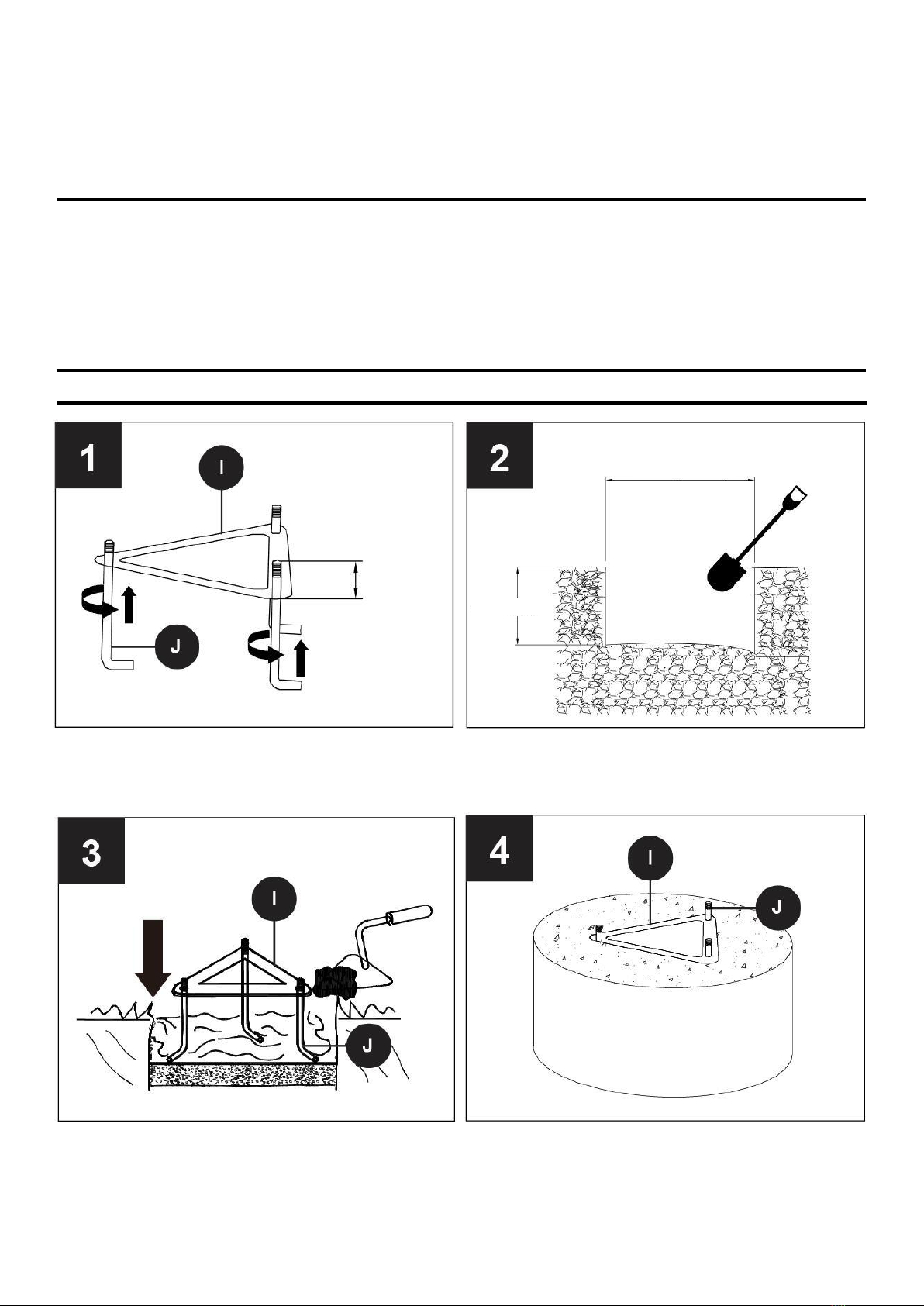
Fill the hole with concrete and insert the Concrete Mounting Bracket (I) and Anchor Bolts (J) before
the concrete dries. Allow concrete to dry before installing Pole Assembly.
4
Thread three Anchor Bolts (J) into the Concrete Mounting Bracket (I) allowing for 5 cm (2 in) above
the Mounting Bracket. Excavate a hole in the ground that measures at minimum 25.4 cm (10 in) in
diameter and has a minimum depth of 12.7 cm (4 in).
No
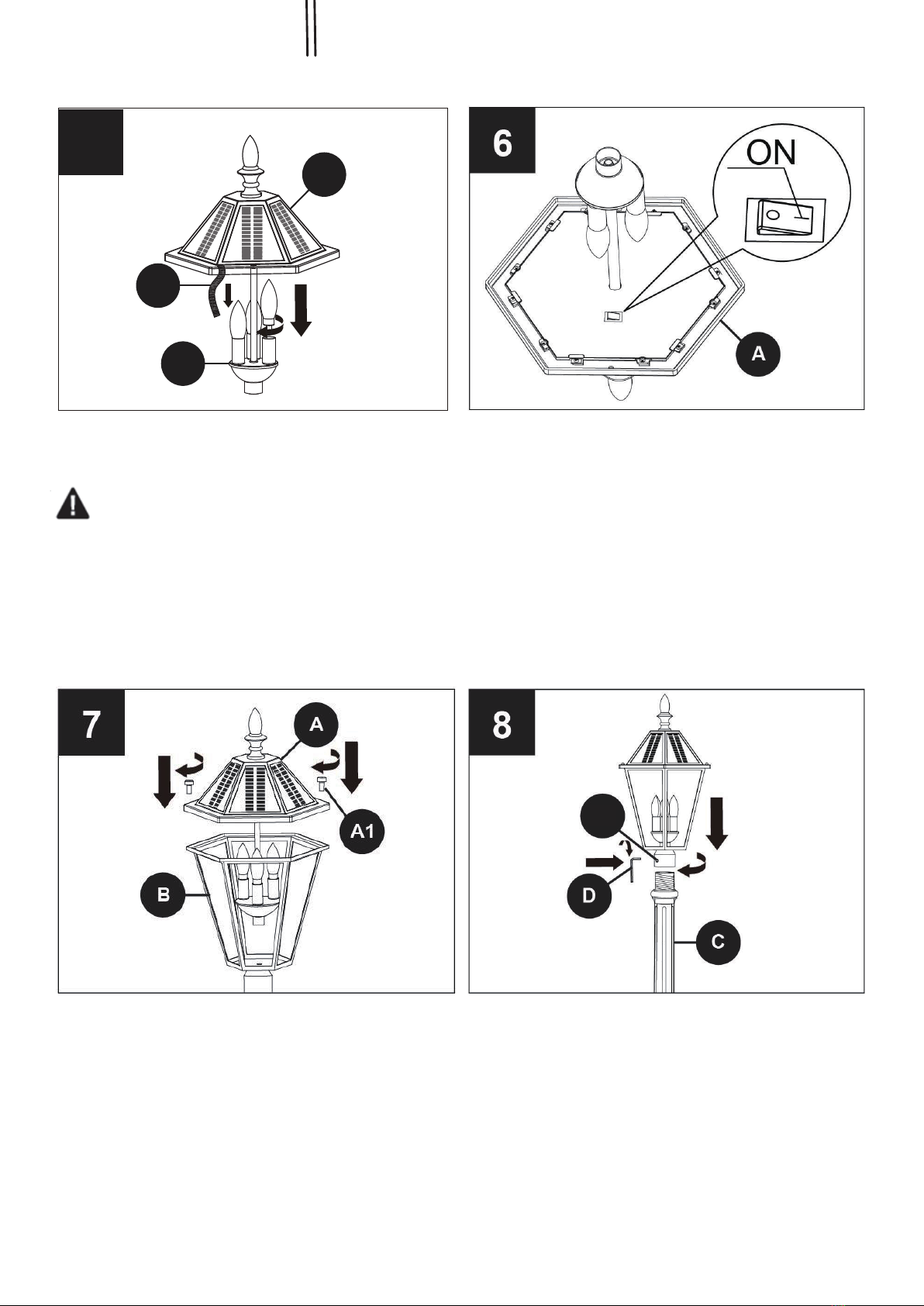
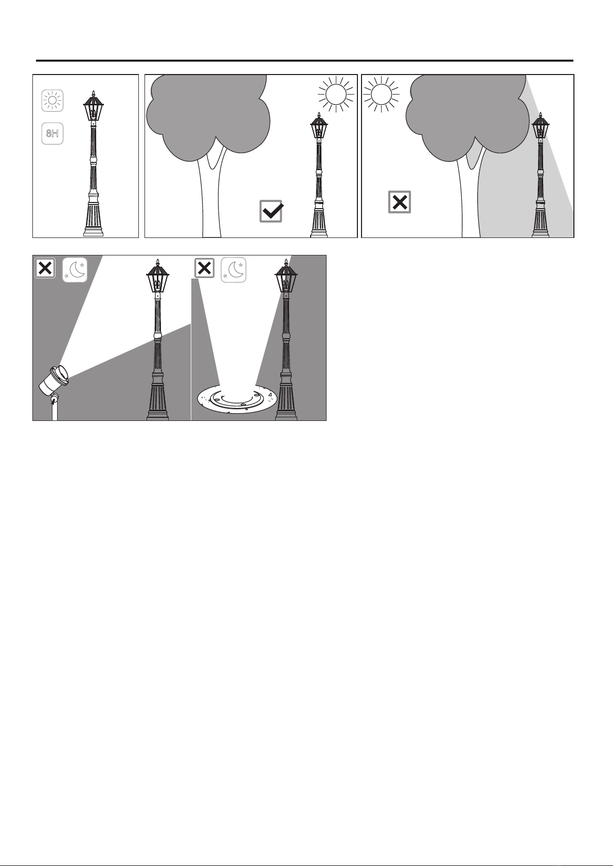
Note: Batteries may have become depleted due to lack of sunlight for an extended
period causing the bulbs to not illuminate. Please place the solar head in direct
sunlight for at least 6 hours prior to assembly.
te: Charging conditions differ by time zone locations and affects total hours of light discharge.
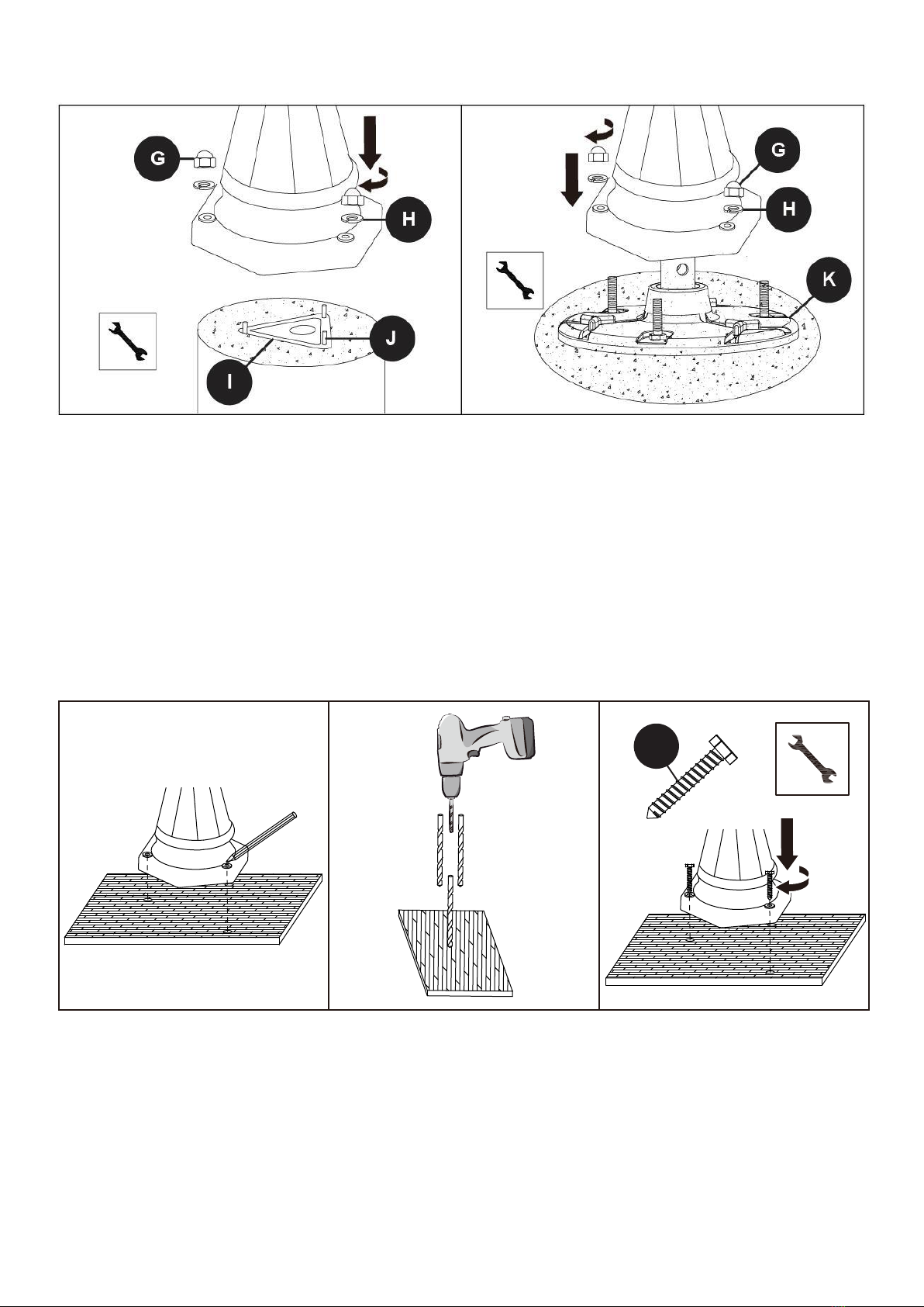
DETERMINE DESIRED INSTALLATION-PERMANENT CONCRETE PAD OR GROUND STAKE
INSTALLATION: PERMANENT CONCRETE PAD
Note: The concrete and the Concrete Mounting Bracket (I) should be at GROUND LEVEL,
with the Anchor Bolts (J) 2 inches above the ground.
PREPARATION
Before beginning to assemble or installing lighting fixture, make sure all parts are present. Compare
parts with package contents list and hardware contents list. If any part is missing or damaged, do
not attempt to assemble, install or operate the product.
Estimated Assembly Time: 30-60 minutes.
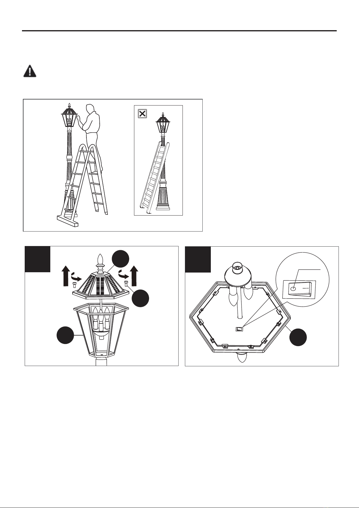
Tools Required for Assembly: Flathead Screwdriver, Phillips Screwdriver, Adjustable Wrench/Pliers
1/2 in Wrench, ladder and hammer.
25.4 cm / 10 in
12.7 cm / 4 in
5 cm / 2 in

5
INSTALLATION: GROUND STAKE
Install three Hex Bolt (P) into Ground Base Insert (K), and tighten with Nut (O).
Attach the Large Ground Stake (M) to the Ground Base Insert (K) by screwing three Ground Stake
Screws (Q) tight with Phillips screwdriver. Then insert Turn Rod (N).
Turn ground stake assembly clockwise by using Turn Rod (N) into the dirt until Ground Base Insert (K)
is tight against the dirt. Insert and pound the three smaller Ground Stakes (L) into the dirt with a
hammer (not included).
Note: Make sure the bubble in the level found at the top of the Ground Stake (M) is centered and
level so the Post Assembly is in a perfect vertical position.

6
ASSEMBLY INSTRUCTIONS
Remove the preassembled Set Screw (C1) from Top Pole (C) and screw Top Pole (C) clockwise
onto Middle Pole (E). Re-insert Set Screw (C1), then tighten with Allen Wrench (D). Remove the
preassembled 3 Base Screws (F1) from Base (F) with a Phillips screwdriver (not included).
Save for later use.
Secure Middle Pole (E) to Base (F) with Base Screws (F1). Tighten with a Phillips screwdriver.
Remove Thumbscrew (A1), then detach Solar Panel Top (A) from Lamp Head (B). Take out
Solar LED Bulbs (B1) from their shipping boxes.
4
A
A1
BB1

7
Install Solar LED Bulbs (B1), and pull off Ribbon (A3) and discard. Turn ON the switch in Solar Panel
Top (A).
LED lights will not automatically turn on unless the battery has been charged and it is
dark outside. You can test the lights by placing the empty box upside down over the Post Light Head.
Once darker, the LED lights should turn on in several seconds.
Attach Solar Panel Top (A) to Lamp Head (B) with the previously removed two Thumbscrews (A1).
Tighten with flathead screwdriver (not included). Carefully screw the lamp head onto Top Pole (C),
securing with the preassembled Set Screw (B2). Tighten with Allen Wrench (D).
7
Warning:
5
B1
A
A3
B2

8
Installation: Concrete Pad Installation: Ground Stake
With the help of another person, place the pole
a
and Anchor Bolt (J). Secure with Cap Nut (G)
and Washer (H). Tighten with a 1/2 inch
wrench (not included).
ssembly over Concrete Mounting Bracket (I)
a
Secure with Cap Nut (G) and Washer (H).
Tighten with a 1/2 inch wrench (not included).
ssembly over Ground Base Insert (K).
CAUTION: Allow the concrete to dry before
installing the pole assembly.
Installation: Wood Deck
Mark 3 points on the deck by
using the fixture base holes.
Drill with a suitable drill bit.
CAUTION:The thickness of the
deck must be greater than
10mm or about 1/2" thick.
Secure the pole base assembly
to the deck by tightening 3
hex-head self-drilling screws (R).
With the help of another person, place the pole
R

9
Charging: Charge in direct sunlight for 8-10 hours.
Location: Choose location with minimum 6-8 hours sunlight. When choosing a spot for your solar
light, ensure that the device is not placed near nighttime light sources such as porch lighting or
street lighting.
Dusk To Dawn: The light will not activate during daylight hours. At sundown the light will go on
automatically and last approximately 6-8 hours
Cleaning solar panels: It is important that dirt and debris is kept off of the solar panel to the greatest
extent possible. A dirty solar panel will not fully charge the battery and thus shorten the battery life.
Battery replacement: Generally speaking, the rechargeable battery should be replaced every two
years in order to maintain the maximum capacity. Please refer to the specs for max charge cycles.
Note: Run times and lighting performance will vary depending upon sunlight and weather conditions.
CAUTIONS: BATTERY INSTRUCTIONS
● Always purchase the correct size and grade of battery by ordering the replacement battery part
number found in the Parts Description page.
● Ensure the batteries are installed correctly.
● Remove batteries from equipment which is not to be used for an extended period of time.
For recycling and disposal of batteries to protect the environment, please check the internet or your
local phone directory for local recycling centers and / or follow local government regulations.
MAXIMIZING SOLAR LIGHT POST PERFORMANCE
8H

10
BATTERY/BULB REPLACEMENT
Replacement batteries and bulbs are available thru LUTEC USA by calling 877-714-8669(English
model number for the battery is 9700356000, the model number for the bulb
Warning: The supplied LED bulbs have been specially developed for use with the solar post
light model 12513LE-SL and must be replaced with model 9700357000. The use of any other type
bulbs will not function in the fixture.
Remove Thumbscrew (A1) then detach Solar Panel Top (A) from Lamp Head (B). Turn off the
power switch in Solar Panel Top (A).
Speaking Only). The
is 9700357000.
1
B
A
A1
2
OFF
A

11
Remove the preassembled Battery Cover Screw (A5) from the Battery Cover (A4) with a Phillips
screwdriver (not included). Then remove the Battery Cover (A4). Remove the old Battery (A2) and
unplug the black battery cord. If an LED bulb is broken, remove the broken Solar LED Bulb (B1)
and replace.
Plug new black battery cable into light fixture. Insert new battery into battery compartment by
carefully placing battery cable into the cable storage area under battery. Install new LUTEC LED bulb.
Attach theBattery Cover (A4) to Solar Panel Top (A) with Battery Cover Screw (A5) removed in step 3.
Tighten with a Phillips screwdriver (not included).
3
A
A5
A4
6
A
A5
A4
5
A
4
A
A2
B1

12
Turn ON the switch in Solar Panel Top (A). Attach Solar Panel Top (A) to Lamp Head (B) with the
two Thumbscrews (A1). Tighten with flathead screwdriver (not included).
CARE AND MAINTENANCE
To clean and wipe with a damp, non-abrasive cloth.
TROUBLESHOOTING
PROBLEM POSSIBLE CAUSE CORRECTIVE ACTION
The light will not go on.
1. Switch OFF.
2. The battery is completely
discharged.
3. DUSK TO DAWN activited.
4. The bulb is loose.
5. Interference from other light
source.
6. The battery is not charged
1. Set to ON.
2. Charge for 6-8 hours in direct
3. Check at night.
4. Re-tighten the bulb.
5. Relocate the solar post light.
6. Make sure the solar panel is in
direct sunlight.
The fixture shakes in high
winds.
1. The mounting bracket could
be loose.
2. The insert may be loose.
3. The screws and cap nuts
may be secured incorrectly.
1. Make sure the mounting
bracket screws are tightened.
2. Make sure the insert is
assembled completely and
tightly.
3. Make sure the screws and cap
nuts were secured tightly.
The lights come on during
the daylight.
1. The light may be installed
in a dark location.
1. Relocate to sunny location.
sunlight.
8
B
A
A1

13
3-YEAR LIMITED WARRANTY
If this product fails due to a defect in materials or workmanship within three (3) years (Battery and
bulbs excluded) from the date of purchase, return it along with proof of date of purchase and it will
be replaced with the same or comparable model free of charge by LUTEC USA LLC..
This warranty is void if damage or defect has resulted from accident, abuse, misuse or faulty repair.
This warranty gives you specific legal rights and you may have other rights that vary from state to
state.
Imported by:
LUTEC USA LLC
149B Houston Road
Troutman, NC 28166
1-(877)714-8669
(English Speaking Only)
Made in China
Distributed by:
Costco Wholesale Corporation
P.O. Box 34535
Seattle, WA 98124-1535
USA
1-800-774-2678
www.costco.com
Costco Wholesale Canada Ltd.*
415 W. Hunt Club Road
Ottawa, Ontario
K2E 1C5, Canada
1-800-463-3783
www.costco.ca
* faisant affaire au Québec sous
le nom les Entrepôts Costco
Importado por:
Importadora Primex S.A. de C.V.
Blvd. Magnocentro No. 4
San Fernando La Herradura
Huixquilucan, Estado de México
C.P. 52765
RFC: IPR-930907-S70
(55)-5246-5500
www.costco.com.mx
Costco Wholesale Australia Pty Ltd
17-21 Parramatta Road
Lidcombe NSW 2141
Australia
www.costco.com.au
Costco Wholesale UK Ltd /
Costco Online UK Ltd
Hartspring Lane
Watford, Herts
WD25 8JS
United Kingdom
01923 213113
www.costco.co.uk
Costco Wholesale Spain S.L.U.
Polígono Empresarial Los Gavilanes
C/ Agustín de Betancourt, 17
28906 Getafe (Madrid) España
NIF: B86509460
900 111 155
www.costco.es
Costco Wholesale Iceland ehf.
Kauptún 3-7, 210 Gardabaer
Iceland
www.costco.is
Costco France
1 avenue de Bréhat
91140 Villebon-sur-Yvette
France
01 80 45 01 10
www.costco.fr
Costco Wholesale Japan Ltd.
3-1-4 Ikegami-Shincho
Kawasaki-ku, Kawasaki-shi,
Kanagawa 210-0832 Japan
0570-032600
www.costco.co.jp
Costco Wholesale Korea, Ltd.
40, Iljik-ro
Gwangmyeong-si
Gyeonggi-do, 14347, Korea
1899-9900
www.costco.co.kr
Costco Wholesale New Zealand Limited
67 Maki Street
Massey, Auckland 0814
New Zealand
www.lutec.com
Shanghai Minhang Costco Trading Co., Ltd
No. 235, ZhuJian Road
Minhang District, Shanghai
China 201106
+86-21-6257-7065

14
IMPORTANT:
LIRE ATTENTIVEMENT ET CONSERVER
POUR CONSULTATION ULTÉRIEURE
Modèle 12513LE-SL
ITM. / ART. 1900527
Français
Lampadaire solaire à DEL
Manuel d’utilisation

15
CONTENU DE L’EMBALLAGE
I
J
K
L
M
N
O
P
Q
A
A1
B
B1
C
E
F
F1
G
H
D
A2
B2
C1
A3
A5
A4
R

16
PIÈCE DESCRIPTION QUANTITÉ
A Tête solaire 1
A1 Vis de serrage 2
A2 Batterie (modèle de remplacement : 9700356000) 1
A3
Ruban
1
A4
Couvercle de la batterie
1
A5
Vis du couvercle
1
B
Lampe
1
B1
Ampoules solaires à DEL (modèle de remplacement : 9700357000)
4
B2 Vis de pression 1 1
C Mât supérieur 1
C1 Vis de pression 2 1
D Clé hexagonale de 1/8 po 1
E Mât inférieur 1
F Base 1
F1
Vis de la base
3
G
Écrous borgnes de 13/32 po
3
H
Rondelles de 13/32 po
3
I Support de fixation pour béton 1
J Boulons d’ancrage 3
K Raccord de la base 1
L Petits piquets de sol de 21 cm (8 5/16 po) 3
M Long piquet de sol de 44,5 cm (17 1/2 po) 1
N Tige de rotation 1
O
Écrous de 13/32 po
3
P
Vis hexagonales de 13/32 x 2 3/16 po
3
Q
Vis pour piquet de sol de 3/16 x 7/8 po
3
CARACTÉRISTIQUES :
Modèle : 12513LE-SL
Couleur des DEL : 2 700 K
Lumens : 300 lm
Puissance totale : 6 W
Batterie : Lithium-ion
Tension : 7.4 V
Capacité de la batterie : 2 200 mAh
Source d’alimentation : Panneau solaire monocristallin en silicone
Durée d’éclairage : Jusqu’à 10 heures
Dimensions : 31 x 26 x 227 cm (12 7/32 x 10 1/4 x 89 3/8 po)
CONSIGNES DE SÉCURITÉ
Lire attentivement le présent guide au complet et s’assurer de bien le comprendre avant de
monter, d’installer ou d’utiliser le produit.
Le lampadaire solaire doit être placé au soleil pour recharger sa batterie; il doit être installé à un endroit où il sera exposé
directement au soleil pendant au moins huit heures.
N.B. : L’exposition au soleil varie selon le fuseau horaire, ce qui peut avoir une incidence sur la durée d’éclairage totale.
AVERTISSEMENT
R
Vis hexagonales autoperceuses de 2 1/2 po
3

Visser les trois boulons d’ancrage (J) au support de fixation pour béton (I) en laissant
5 cm (2 po) dépasser au-dessus du support. Creuser un trou d’au moins 25,4 cm (10 po)
de diamètre et d’au moins 12,7 cm (5 po) de profondeur.
17
N.B. : La batterie peut s’être déchargée en raison d’un long manque d’exposition au soleil,
ce qui empêchera les ampoules de s’allumer. Placer la tête solaire directement au soleil
pendant au moins six heures avant le montage.
CHOISIR L’EMPLACEMENT DU SOCLE DE BÉTON PERMANENT OU DU PIQUET DE SOL
INSTALLATION DU SOCLE DE BÉTON PERMANENT
PRÉPARATION
Avant de monter ou d’installer le lampadaire, s’assurer qu’il ne manque aucune pièce. Comparer le contenu de l’emballage
avec la liste des pièces et des éléments de quincaillerie. Si des pièces sont manquantes ou endommagées, ne pas tenter
de monter, d’installer ou d’utiliser le produit.
Temps de montage estimé : 30 à 60 minutes.
Outils requis : Tournevis à tête plate, tournevis à pointe cruciforme, clé à molette ou pinces, clé de 1/2 po, échelle et
marteau.
Remplir le trou de béton et insérer le support de fixation pour béton (I) et les boulons d’ancrage (J)
avant que le béton ne sèche. Laisser le béton sécher complètement avant d’installer le lampadaire.
N.B. : La surface du béton et le support de fixation pour béton (I) doivent être RAS AU SOL,
et les boulons d’ancrage (J) doivent dépasser de 5 cm (2 po) du sol.
25,4 cm (10 po)
12,7 cm (5 po)
5 cm (2 po)

18
INSTALLATION DU PIQUET DE SOL
Insérer les trois vis hexagonales (P) dans le raccord de la base (K) et les serrer avec les écrous (O).
Attacher le long piquet de sol (M) au raccord de la base (K) en vissant les trois vis pour piquet de
sol (Q) avec un tournevis à pointe cruciforme (non compris), en serrant complètement. Insérer la
tige de rotation (N).
Insérer le piquet monté dans le sol en le tournant dans le sens horaire avec la tige de rotation (N)
jusqu’à ce que le raccord de la base (K) soit fermement appuyé sur le sol. Insérer les trois petits
piquets de sol (L) et les enfoncer dans le sol avec un marteau (non compris).
N.B. : S’assurer que la bulle du niveau au sommet du piquet de sol (M) est bien centrée et au niveau,
pour que le mât soit parfaitement vertical.

19
INSTRUCTIONS DE MONTAGE
Dévisser la vis de pression (C1) préinstallée sur le mât supérieur (C), puis visser celui-ci (C) sur le
mât inférieur (E) en tournant dans le sens horaire. Réinsérer la vis de pression (C1) et la serrer avec
la clé hexagonale (D). Retirer les trois vis (F1) préinstallées sur la base (F) à l’aide d’un tournevis à
pointe cruciforme (non compris). Les mettre de côté.
Fixer le mât inférieur (E) à la base (F) avec les vis de la base (F1) en les serrant avec un tournevis
à pointe cruciforme. Retirer les vis de serrage (A1), puis détacher la tête solaire (A) de la lampe (B).
Sortir les ampoules solaires à DEL (B1) de leur emballage.
4
A
A1
BB1

20
Installer les ampoules solaires à DEL (B1), puis retirer et jeter le ruban (A3). Mettre l’interrupteur
de la tête solaire (A) en position allumée.
Avertissement : Les ampoules à DEL ne s’allumeront pas automatiquement si la batterie est
déchargée ou s’il fait clair à l’extérieur. Pour tester les ampoules, placer une boite vide sur la
lampe. À la noirceur, les ampoules à DEL devraient s’allumer après quelques secondes.
Attacher la tête solaire (A) à la lampe (B) avec les deux vis de serrage (A1) retirées plus tôt, et
les serrer avec un tournevis à tête plate (non compris). Visser doucement la lampe (B) sur le
mât supérieur (C). La fixer avec les vis de pression (B2) préinstallées; serrer celles-ci avec la
clé hexagonale (D).
5
5
B1
A
A3
B2
Other manuals for 12513LE-SL
1
This manual suits for next models
1
Table of contents
Languages:
Other LUTEC Lantern manuals