LUX LUMEN StarGuide MINI 10640 User manual

StarGuide MINI
10640
Nocontrolelectronics on board

StarGuideMINIp.2/25
LUX LUMEN-Kernenergiestraat 53A-2610WILRIJK -BELGIUM
T: +323 293 3550 –F:+32 3293 3544
www.lux-lumen.com
CONTENT
1PICTURE.................................................................................. 3
1.1 GENERAL....................................................................................... 3
2DIMENSIONS.......................................................................... 4
3SAFETY INFORMATION........................................................... 5
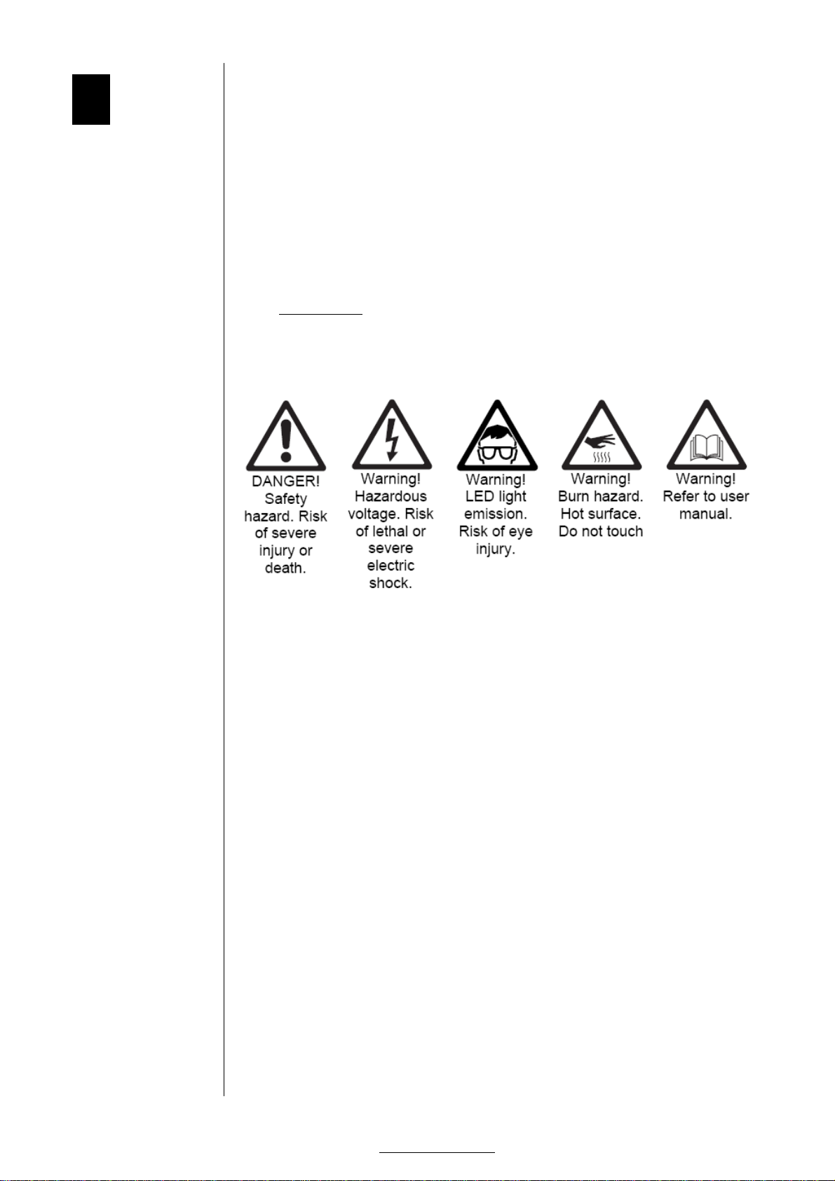
3.1 SYMBOLS ...................................................................................... 5
3.2 PROTECTIONFROMELECTRICSHOCK....................................................... 6
3.3 PROTECTIONSFROMFIREAND BURNS...................................................... 6
3.4 PROTECTIONFROM INJURY .................................................................. 7
3.5 DISPOSINGOFTHISPRODUCT .............................................................. 7
4PHYSICALINSTALLATION....................................................... 8
4.1 UNPACKING.................................................................................... 8
4.2 LOCATIONANDORIENTATION ............................................................... 9
4.3 MOUNTING..................................................................................... 9
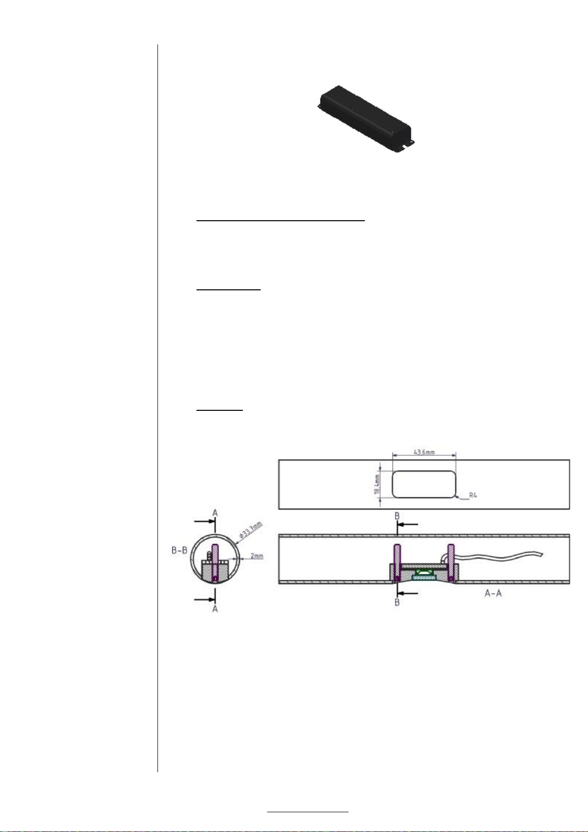
4.4 CUTOUT........................................................................................ 9
5EXTERNALCONNECTIONS..................................................... 10
5.1 DC POWER INPUT........................................................................... 10
6EMCAND SAFETY REQUIREMENTS........................................ 11
7INSTALLATIONSETUP........................................................... 13
7.1 SPECIFICATION.............................................................................. 13
7.2 INSTALLATION............................................................................... 14
7.3 CHOICEOFPOWERSUPPLY ................................................................ 20
8SERVICEAND MAINTENANCE................................................ 21
8.1 SAFETY PRECAUTIONS...................................................................... 21
8.2 CLEANING.................................................................................... 21
9WARRANTY........................................................................... 22
9.1 APPLICATIONOF WARRANTY............................................................... 22
9.2 RMA PROCEDURE........................................................................... 24
10 USED LISTOFABBREVIATIONS......................................... 25

StarGuideMINIp.5/25
LUX LUMEN-Kernenergiestraat 53A-2610WILRIJK -BELGIUM
T: +323 293 3550 –F:+32 3293 3544
www.lux-lumen.com
3Safetyinformation
Beforeinstalling, powering up,or servicing theStarGuideMINI
led-unit,ithishighly recommended thatyou read thismanual
and insure yourselfthatyou completelyunderstanditscontent.
Observethesafety precautionsin thismanual.Installand
operatetheled-unitonly as described in thismanual,andin
conformity with localregulations.If youhaveany questionshow
tooperatethisproductsafely,pleasecontactyourpoint ofsale.
3.1 Symbols
Following symbolsare used toidentify important safety
informationon theproductand in thismanual.

StarGuideMINIp.6/25
LUX LUMEN-Kernenergiestraat 53A-2610WILRIJK -BELGIUM
T: +323 293 3550 –F:+32 3293 3544
www.lux-lumen.com
3.2 Protection fromelectric shock
Although thisdeviceitselfdoesnotoperatewith dangerous
voltages,theinstallationin whichisintended tobeused, can
contain dangerousvoltages.
Shutdown thepower of thecompleteinstallation before carrying
out any installation, or maintenancework.
Useonly ACtoDCcurrent controlled 350 mApower sources,
suitablefor theapplication,and conform tolocalregulations.
Pleaseensure yourself thattheACtoDCcurrent controlled
power supply isabletodeliver therated requirementsof the
completeinstallation.
If any cable,sealorhousing isdamaged, cracked, or reformed,
disconnectthepower of theinstallationimmediately.
For any additionalservicing,notdescribed in thismanual, please
contactyourpointof sale.
3.3 Protections from fireand burns
Donotoperatethisled-unit if ambienttemperatures,isabove
45 °C(113 °F). Itmightbenecessarytoallow theled-unit to
cooldown for 5minutes,before servicing.
Donotmodify theLEDfixture,inaway,notdescribed inthis
manual.

StarGuideMINIp.7/25
LUX LUMEN-Kernenergiestraat 53A-2610WILRIJK -BELGIUM
T: +323 293 3550 –F:+32 3293 3544
www.lux-lumen.com
3.4 Protection frominjury
Ensure yourself thatall components,coversare securely
fastened. Verifythattheled-unit isfirmly fixed toitssupporting
railing. Ensure yourself thatthevibration, will notloosen the
screws,which hold themodule.Takeprecautionsif necessary by
applyingalow gradelocking glue(Loctite®222).
3.5 Disposingof this product
ThisLEDlighting deviceismanufactured in compliancewith
directiveof theEuropean community:wasteof electricaland
electronicallyequipment. Pleasehelp topreserveour
environment, and ensure thatthisproductwill berecycled
properly attheend of itslife.

StarGuideMINIp.8/25
LUX LUMEN-Kernenergiestraat 53A-2610WILRIJK -BELGIUM
T: +323 293 3550 –F:+32 3293 3544
www.lux-lumen.com
4Physical installation
Thank you for selectingthisStarGuideMINIled-unitas best
solutionin yoursetup.
Warning! Readthesafety precautionsin thismanualbefore
integrating thiscardintoyourinstallation.
Installation mustbecarried out by qualified professionalsonly.
4.1 Unpacking
TheStarGuidemodulesare only soldinsets,together with their
dedicatedpower supply and all accessories.
Thefollowing itemsare includedin yourset:
•Anumber of StarguideMINIled-units each with itstwo
Allen keybolts:
•Anumber of push sealconnectors(named further in this
document:Scotchlok™)
•An Allen key nr2:
•Atube,or flacon with threatlockingglue.

StarGuideMINIp.9/25
LUX LUMEN-Kernenergiestraat 53A-2610WILRIJK -BELGIUM
T: +323 293 3550 –F:+32 3293 3544
www.lux-lumen.com
•Adedicated LEDdriver:
Setsare delivered in acarton box and protectiveantistatic
packaging,with thismanual.
4.2 Location and orientation
ThisStarGuideMINIled-unit itself canbeused in all different
directionsand orientations.
4.3 Mounting
TheStarGuideMINIled-unit isdesignedtobeused on a
stainless steeltubeof 33.7mm diameter,wall-thickness of2
mm. Duetotheuniqueconcept of fixation, installation canbe
doneeasily,withthehelp of asmall allen Key.
In caseof problems,or doubts,pleasecontactyourpointof sale.
4.4 Cutout
Dimensionsof cutout in thetubecanbefound here:

StarGuideMINIp.10/25
LUX LUMEN-Kernenergiestraat 53A-2610WILRIJK -BELGIUM
T: +323 293 3550 –F:+32 3293 3544
www.lux-lumen.com
5External connections
5.1 DC powerinput
Safetyprecautions
Never connectthelivepower on theinput terminalsof the
StarGuideMINIled-unit!
In caseof doubts,contactyourpoint ofsale.
Polarity
TheStarGuideMINIled-unit ispolarity sensitive.Soobserve
polarity and colourcabling:
•Red =positive
•Black =negative
Powersupply:Ratedcurrent
Therated inputcurrent of therailing moduleis350 mADC.
Verify thattheyourpower supply hasacurrent controlled
output.Ifyou are notsure donotconnectthepower supply!In
caseof doubt,pleasecontactyourpointof sale.
Powersupply:Ratedcurrent
AStarGuideMINIled-unit consumesapprox 1watt power,which
resultsat350 mAataforward voltageof ±2.8to3.2Volt.

StarGuideMINIp.11/25
LUX LUMEN-Kernenergiestraat 53A-2610WILRIJK -BELGIUM
T: +323 293 3550 –F:+32 3293 3544
www.lux-lumen.com
6EMC andsafetyrequirements
TheStarGuideMINIled-unit isfully compliant totheLVDand
EMCdirectiveof theEuropean council, if used inaproperly
designed setup.
EMCrequirements of thepowersupply:
TheStarGuideMINIled-unit isonly intended tobeusedin
lighting applications,and assuch,thecompleteassemblyof led
unitand power supply needstobefullycompliant with the
harmonized standards.
Immunity accordingto:
•EN61547:2009 (GeneralEMCimmunityrequirements
lighting eq.)
•EN61000-4-1:2006(Generalimmunity testing techniques)
•EN61000-4-2:2008(ESDimmunitytest)
•EN61000-4-3:2006+A1:2007 (Radiated immunity test)
•EN61000-4-4:2004(Fasttransientsand burstimmunity)
•EN61000-4-5:2005(Surgeimmunity test)
•EN61000-4-6:2008(Conductedimmunitytest)
•EN61000-4-8:1993(Magneticfield immunity test)
•EN61000-4-11:2004(Voltagevariationsimmunity test)
•EN61000-6-1:2005(Genericstandardsfor immunity)
Emission accordingto:
•EN61000-3-2:2005+A1:2008+A2:2009(Harmonics
emission test<16A)
•EN61000-3-3:2008(Flicker+voltagechangeslimits<16A)
•EN55015:2006+A2:2009 (Conducted +radiated emission
lighting equipment)
To achievethiscompliance,aproper power supply mustbe
supplied. In caseofdoubts,contactyourpoint of sale.
LVDrequirementsof thepowersupply:
TheStarGuideMAXIled-unit isonly intended tobeusedin
lighting applications,and assuch,thecompleteassemblyof led
unitand power supply needstobefullycompliant with following
harmonized standards:
•EN60598:generalrequirementsof lightingequipment.

StarGuideMINIp.12/25
LUX LUMEN-Kernenergiestraat 53A-2610WILRIJK -BELGIUM
T: +323 293 3550 –F:+32 3293 3544
www.lux-lumen.com
Themodulecan becategorized according toEN60598 as
following:
•SELVclass III
•Power supply-cordtypeZ,noremoval, withoutpermanent
damagetotheunit.
•IP 67 for theStarGuideMINIled-unit.
•IK 06 for theStarGuideMINIled-unit.
Pleasenotethatalthough theunitseemstobeSELV,the
completeinstallation isnotSELV,and therailing needsaproper
safety earth connection!

StarGuideMINIp.13/25
LUX LUMEN-Kernenergiestraat 53A-2610WILRIJK -BELGIUM
T: +323 293 3550 –F:+32 3293 3544
www.lux-lumen.com
7Installation setup
7.1 Specification
TheStarGuideMINIled-unit isasmalland efficient solution
which can beeasilyintegratedin acircularrailing tube.
Itusesacurrent controlled power supply andallmodulesare
connected in series.Up to100 modulescan beconnectedin
series,dependingon thepower supplyused.
Pleasenotethatdangerous voltages areused. Always
disconnectthemainpower of thecompleteinstallation, before
executing any workson theinstallation.
•Power consumptioneach StarGuideMINIled-unit:1,2W
•Rated current input:350 mA
•Forward voltageover theled: ±2.8to3.2volt depending on
binningand color
•Ingress protection: IP 67
•Impactprotection:IK 06
•Weight: 32 gr
•Reflector angle:26°
•Body material: 15 µM anodized aluminum
•Transparent glass cover
•Resin epoxy based, and heatconductive
Theled-unitisequipped with a‘antifuse’,soin caseof failure of
onemodulein aseriesstring, all other modulesremain fully
functional.
Standardcablelength is1200 mm for positivepolarity,and200
mm for negativepolarity,somaximum pitch isapprox 100 cm
between themodules.
Themoduleispolarity sensitive.
Connectionsare doneby using Scotchlok™connectors,supplied
together with theStarGuideMINIled-unit.

StarGuideMINIp.14/25
LUX LUMEN-Kernenergiestraat 53A-2610WILRIJK -BELGIUM
T: +323 293 3550 –F:+32 3293 3544
www.lux-lumen.com
7.2 Installation
Tools
Theinstallation of theStarGuideMINIled-unitisstraightforward,
and needsmainly two tools:
•Allen key NR2:
•UniversalPliers:
Note: Adedicated crimping toolisavailabletoshrink the
Scotchlok™connectors.In caseof abigger installation, it might
beusefultohavethiscrimping toolin yourtoolset.
Thistoolisavailableatyourpoint of sale.

StarGuideMINIp.15/25
LUX LUMEN-Kernenergiestraat 53A-2610WILRIJK -BELGIUM
T: +323 293 3550 –F:+32 3293 3544
www.lux-lumen.com
SCHEMATICof installation
Sotheunitsare connected in seriesin onestring of elements.A
‘retourline’makestheloop closed withthepower supply.
Each red wire isconnected withtheblack wire,coming fromits
neighbor.Theelectricalconnectionismadewith thesupplied
Scotchlok™connectors.
STEP 1:
Insertablack cableatthelastcutout,direction totheleddriver.
Sothecableisfromend tobegin of therailing, and has enough
cablelength tobeconnected tothedriver.
Theresult willbelikethis:
At theplaceof thelastmodule,leaveapprox 20 cm cableout of
thetube,and tapeitthetube,soit will notgetlostin thetube.

StarGuideMINIp.16/25
LUX LUMEN-Kernenergiestraat 53A-2610WILRIJK -BELGIUM
T: +323 293 3550 –F:+32 3293 3544
www.lux-lumen.com
STEP 2:
Starttheinstallation atthelastmodule,by connecting theblack
cableon themodule,with theblack ‘loop-back cable’by using
theScotchlok™connector.Pleasenote:thisistheonly place,
where ablack cableisconnected withanother black cable.
Insertthetrimmedwire endsintotheconnector.Donotstrip the
wires.Makesure allwiresare inserted pastthemetalelement to
theback wall oftheconnector.
Takeauniversalpliers,and placetheconnector between the
jaws.
Makesure thetwo black wiresremain fullyinserted totheback
wall of theconnector.

StarGuideMINIp.17/25
LUX LUMEN-Kernenergiestraat 53A-2610WILRIJK -BELGIUM
T: +323 293 3550 –F:+32 3293 3544
www.lux-lumen.com
Squeeze thehandlesof thepliers,sothered cap remainsflush
with therim oftheconnector body.
You will see thatagel, which islocatedin thered cap,willbe
injectedin thecableinsertions.
After verifying thatthecableisstillin good position,you can put
theScotchlok™connector in thetube.
STEP 3:
Insertthered cablein thecutout, and glideit in tothenext
module.

StarGuideMINIp.18/25
LUX LUMEN-Kernenergiestraat 53A-2610WILRIJK -BELGIUM
T: +323 293 3550 –F:+32 3293 3544
www.lux-lumen.com
STEP 4:
Makesure both screwsare likeon following photoand apply
somethread locking gluetoboth screws.
After applying theglue,turn thescrewsback toapprox this
situation:
STEP 5:
Insertthemoduleintothecutout.Thescrew has tobeapprox 10
mm visiblefrom thefront.

StarGuideMINIp.19/25
LUX LUMEN-Kernenergiestraat 53A-2610WILRIJK -BELGIUM
T: +323 293 3550 –F:+32 3293 3544
www.lux-lumen.com
STEP 6:
Insertboth screwscompletetotheend, makesure you donot
perforatetheblack ‘loop-back’cable.
Theresult islookinglikethis:
STEP 7:
Proceed with nextmodule,starting from step 3.
Note: theinstaller has toensure him(her)-self thatthescrew will
notperforateany of thecabling, locatedin therailing!
Never usean electricaltooltofasten thefixing screwsin the
led-unit.

StarGuideMINIp.20/25
LUX LUMEN-Kernenergiestraat 53A-2610WILRIJK -BELGIUM
T: +323 293 3550 –F:+32 3293 3544
www.lux-lumen.com
STEP 8:
At thebeginning ofthesetup,you will havetheblack loop-back
cable,and ared cable,coming from thefirstmodule.These
cablesneed tobeconnected tothepower supply, delivered
together with yoursetup.
7.3 Choiceof powersupply
Sincethisled-unitiscurrent driven, thevoltagethatthepower
supply has todeliver,isdependenton thenumber of modules
thatare connectedin series.
Thevoltagedrop over onemoduleisapprox 3volt. Soin caseof
12 modules,thecurrent in thecircuitwill be350 mA, and the
voltagedrop over thecompletecircuit will be:
12 modulesx 3volt(over onemodule)=36 volt.
Itisimportant tounderstand thatnotallcurrent sourcesare
capableof producing acurrent of 350 mAat36 volt.
In thisexample,thepower generated by thepower supply is:
0,350 (A) x36 (volt)=12,6watt.
Wespecify three different power supply’s touse,dependingon
thenumber of unitsconnected inseries.
Numberof
modules
Currentin
circuit
M
in
voltage
Max
voltage
Power
supplymfr.
Power
supplytype
1to4
350 mA
2V
14 V
Lightech
LED
-
4W
350mA
4to19
350 mA
12
V
5
8
V
Lightech
LED
-
18W
DC350mA
20 to50
350 mA
60 V
210 V
Philips
Advance
LEDINTA
350C210DHO
51
to100
350 mA
120 V
425 V
Phi
llips
Advance
LEDINTA
0350C425FO
Manualsof theLEDdriversare supplied with yoursetup.
Notethatthepower supply LEDINTA350C210DHOhas a1-10
volt dim-input.When yoursetup needsnodimming,thewires
can stayunconnected.
Table of contents
Other LUX LUMEN Light Fixture manuals
Popular Light Fixture manuals by other brands

Cooper Lighting
Cooper Lighting ComboLight CO Recessed w/ Trim Series none user manual

UV Resources
UV Resources X-Plus General Installation Instructions

Star Headlight & Lantern
Star Headlight & Lantern DLXT-121 Series Quick install guide

Ayrton
Ayrton argo 6 WASH user manual

Ikan
Ikan IFB576-2PT-KIT-CH quick start guide

Ayra
Ayra ERO 030 user manual