LuxeAir DRH70230BS Installation guide

Use, Care, and Installation Guide
Model number:
Serial Number:
DEC19.0201
DRH70230BS
DRH70236BS
DRH70248BS


1
SAFETY NOTICE ................................................................. 2-3
LIST OF MATERIALS....................................................... 4
INSTALLATION
Ducting Calculation Sheet....................................... 5
Mounting Height & Clearance................................ 6
Ducting Options ........................................................... 7
Specications ............................................................... 8
Mounting the Range Hood & Electrical.............. 9
Horizontal Ducting Conversion.............................. 10
CONTROLS
Electronic Touch .......................................................... 11
MAINTENANCE
Cleaning, Filters & Lights......................................... 12
CFM SELECT CONVERSION................................................. 13
TROUBLESHOOTING................................................................ 14
WIRING DIAGRAMS................................................................... 15
LIST OF PARTS AND ACCESSORIES .............................. 16
WARRANTY.................................................................................... 17
Table of Contents

Important Safety Notice
READ AND SAVE THESE INSTRUCTIONS
2
WARNING
TO REDUCE THE RISK OF FIRE OR ELECTRIC SHOCK, DO NOT USE THIS FAN WITH ANY SOLID-STATE CONTROL DEVICE.
WARNING
TO REDUCE THE RISK OF FIRE ELECTRIC SHOCK, OR INJURY TO PERSONS, OBSERVE THE FOLLOWING:
a. Use this unit only in the manner intended by the manufacturer, if you have questions, contact the manufacturer.
b. Beforeservicingorcleaningunit,switchpoweroatservicepanelandlockpaneltopreventpowerfrombeingswitchedonaccidentally.
Whentheservicedisconnectingmeanscannotbelocked,securelyfastenaprominentwarningdevice,suchasatag,totheservice
panel.
CAUTION
Forgeneralventilatinguseonly.Donotusetoexhausthazardousorexplosivematerialsandvapors.Takecarewhenusingcleaning
agentsordetergents.Suitableforuseinhouseholdcookingarea.
WARNING
TO REDUCE THE RISK OF RANGE TOP GREASE FIRE:
a. Neverleavesurfaceunitsunattendedathighsettings.Boiloverscausesmokingandgreasyspilloversthatmayignite.Heatoilsslowly
on low or medium settings.
b. AlwaysturnhoodONwhencookingathighheatorwhenamingfood
c. Cleanventilatingfansfrequently.Greaseshouldnotbeallowedtoaccumulateonfanorlter.
d. Useproperpansize.Alwaysusecookwareappropriateforthesizeofthesurfaceelement.
e. Keepfan,ltersandgreaseladensurfacesclean.
f. Use high setting on hood only when necessary.
g. Don’tleavehoodunattendedwhencooking.
h. Alwaysusecookwareandutensilsappropriateforthetypeofandamountoffoodbeingprepared.
WARNING
TO REDUCE THE RISK OF INJURY TO PERSONS IN THE EVENT OF A RANGE TOP FIRE, OBSERVE THE FOLLOWING:
a. SMOTHERFLAMESwithaclose-ttinglid,cookiesheet,ormetaltray,thenturnotheburner.BECAREFULTOPREVENTBURNS.
Iftheamesdonotgooutimmediately,EVACUATEANDCALLTHEFIREDEPARTMENT.
b. NEVER PICK UP A FLAMING PAN – You may be burned.
c. DO NOT USE WATER, including wet dishcloths or towels – a violent steam explosion will result.
d. Use an extinguisher ONLY if:
1. YouknowyouhaveaClassABCextinguisher,andyoualreadyknowhowtooperateit.
2. Thereissmallandcontainedintheareawhereitstarted.
3. Theredepartmentisbeingcalled.
4. Youcanghttherewithyourbacktoanexit
WARNING
TO REDUCE THE RISK OF FIRE, ELECTRIC SHOCK OR INJURY TO PERSONS, OBSERVE THE FOLLOWING:
a. Installationworkandelectricalwiringmustbedonebyqualiedperson(s)inaccordancewithallapplicablecodesandstandards.
Includingre-ratedconstruction.
b. Sucientairisneededforpowercombustionandexhaustingofgasesthroughtheue(chimney)offuelburningequipmenttoprevent
back-drafting.Followtheheatingequipmentmanufacturer’sguidelineandsafetystandardssuchasthosepublishedbytheNational
FireProtectionAssociation(NFPA)andtheAmericanSocietyforHeating,RefrigerationandAirConditioningEngineers(ASHRAE)and
the local code authorities.
c. When cutting or drilling into wall or ceiling, do not damage electrical wiring and other hidden utilities.
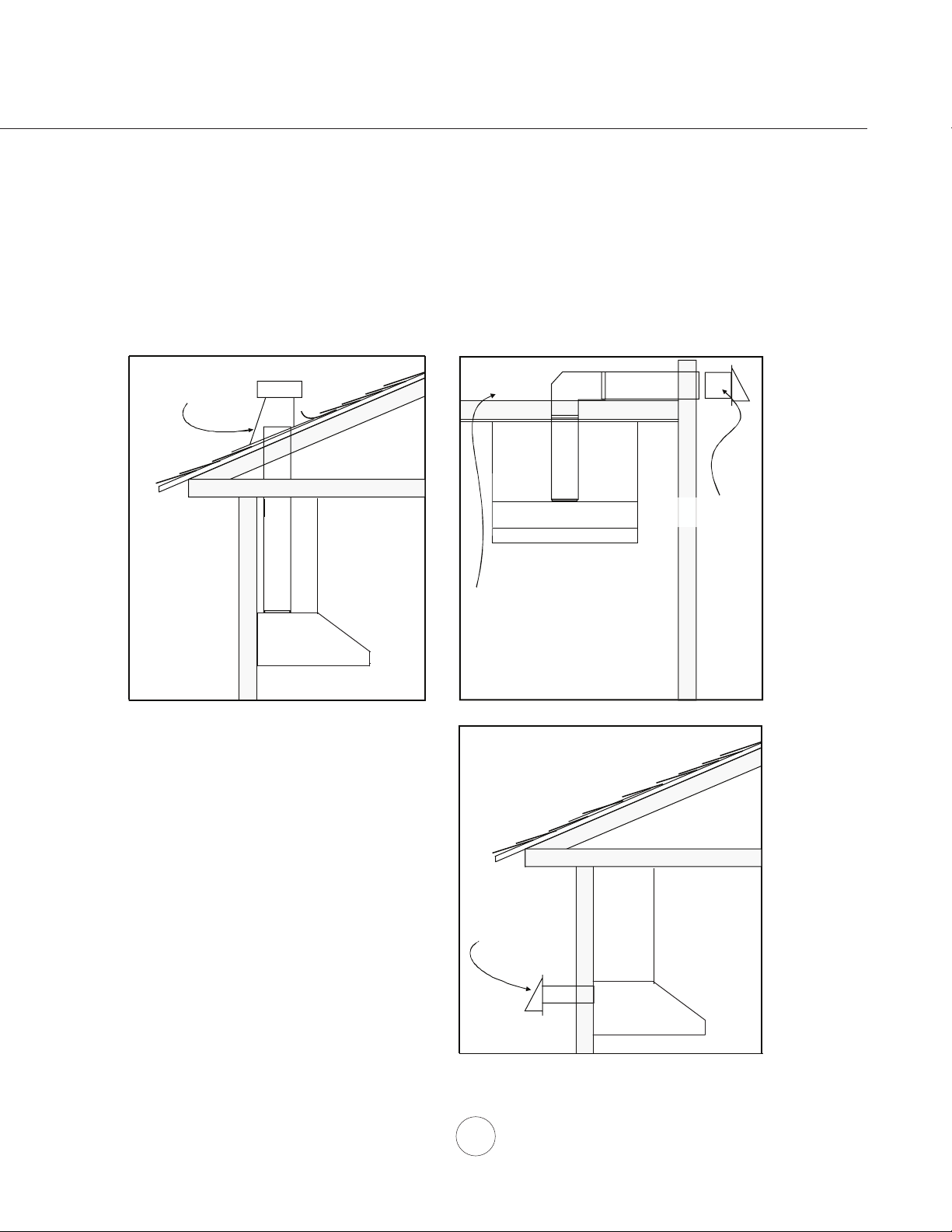
d. Ducted fans must always vent to the outdoors.
e. NEVER place a switch where it can be reached from a tub or shower.
f. Makesurethepowerisobeforeinstalling,wiringormaintenancing.

Important Safety Notice
3
WARNING
TO REDUCE THE RISK OF FIRE, USE ONLY METAL DUCTWORK.
CAUTION
Toreduceriskofreandtoproperlyexhaustairoutside-Donotventexhaustairintospaceswithinwalls,ceilings,
attics, crawl spaces or garages.
OPERATION
Alwaysleavesafetygrillesandltersinplace.Withoutthesecomponents,operatingblowerscouldcatchontohair,ngers
and loose clothing.
The manufacturer declines all responsibility in the event of failure to observe the instructions given here for installation,
maintenance and suitable use of the product. The manufacturer further declines all responsibility for injury due to
negligence and the warranty of the unit automatically expires due to improper maintenance.
ELECTRICAL REQUIREMENTS
Important:
Observe all governing codes and ordinances.
It is the customer’s responsibility:
- Tocontactaqualiedelectricalinstaller.
- To assure that the electrical installation is adequate and in conformance with National Electrical Code, ANSI/NFPA 70
latest edition* or CSA standards C22.1-94, Canadian Electrical Code, Part 1 and C22.2 No.0-M91 - latest edition** and
all local codes and ordinances.
Ifcodespermitandaseparategroundwireisused,itisrecommendedthataqualiedelectriciandeterminethatthe
ground path is adequate.
Do not ground to a gas pipe.
Checkwithaqualiedelectricianifyouarenotsuretherangehoodisproperlygrounded.
Do not have a fuse in the neutral or ground circuit.
*NationalFireProtectionAssociationBatterymarchPark,Quincy,Massachusetts02269
** CSA International 8501 East Pleasant Valley Road, Cleveland, Ohio 44131-5575
This appliance requires a 120V 60Hz electrical supply and connected to an individual properly grounded branch circuit
protectedbya15or20amperecircuitbreakerortimedelayfuse.Wiringmustbe2wirewithground.Pleasealsoreferto
Electrical Diagram on product.
Acablelockingconnector(notsupplied)mightalsoberequiredbylocalcodes.Checkwithlocalrequirements,purchase
and install appropriate connector if necessary.
Cancer and Reproductive Harm - www.P65Warnings.ca.gov
WARNING:
Prop. 65 Warning for California Residents

List of Materials
4
MODELS: RH70230BS, RH70236BS, RH70248BS
PARTS SUPPLIED
1 - Hood
3-Baelters(2forRH70230BS)
2-Halogenlightbulbs(pre-installed)
1 - 10” round transition adapter
1 - Top Ducting Cover Plate
1-Hardwarepackage
HARDWARE PACKAGE CONTENTS
PARTS NOT SUPPLIED
- Ducting, conduit and all installation tools
-Cableconnector(ifrequiredbylocalcodes)
- Duct Cover Accessory
-BacksplashAccessory
Light Bulb Removal
Suction Cup (1)
6# x 1” (4 )
6# x 1-1/2” (4 )
6# x 2” (4 )
M4 x 8 (4)
Wire Caps (3) 3/16 x 3/8” (4)
-WoodBoardtohanghood(WxDxH)
RH70230BS - 27” x 1/2” x 4”
Rh70236BS - 33” x 1/2” x 4”
RH70248BS - 45” x 1/2” x 4”

5
Installation – Ducting Calculation Sheet
Duct pieces To tal
Equivalent number
length x used =
3-1/ 4” x 10”
Rect.,
straight
1 Ft. x ( ) =Ft.
3-1/ 4” x 10”
Rect.to
6” round
transition
5 Ft. x ( ) =Ft.
3-1/ 4” x 10”
Rect.to
6” round
transition
900 elbow
20 Ft. x ( ) =Ft.
6”, 7”, 8”, 10”
Round,
900
15 Ft.
x ( ) =Ft.
6”, 7”, 8”, 10”
Round,
450
9 Ft. x ( ) =Ft.
Ft.
6”, 7”, 8”, 10”
Round,
straight
1 Ft. x ( ) =Ft.
Subtotal column 1 =
Duct pieces To tal
Equivalent number
length x used =
6”, 7”, 8”, 10”
Round, wall
cap with
damper
30 Ft. x ( ) =Ft.
Ft.
Ft.
Ft.
6”, 7”, 8”, 10”
Round
roof cap
30 Ft. x ( ) =Ft.
Subtotal column 2 =
Subtotal column 1 =
Total ductwork =
Maximum Duct Length: For satisfactory air movement,
the total duct length
should not exceed 100 equivalent feet.
6” round to
3-1/ 4” x 10”
rect.
transition
1 Ft. x ( ) =Ft.
6” round to
3-1/ 4” x 10”
rect.
transition
900 elbow
16 Ft. x ( ) =Ft.
7” round to
3 1/ 4” x 10”
rect.
transition
8 Ft. x ( ) =Ft.
7” round to
3-1/ 4” x 10”
rect.
transition
900 elbow
23 Ft. x ( ) =Ft.
elbow
elbow
7” to 6” or
8” to 7” Round
tapered
reducer
25 Ft. x ( ) =Ft.
3-1/ 4” x 10”
Rect.900
elbow
15 Ft. x ( ) =Ft.
3-1/ 4” x 10”
Rect.450
elbow
9 Ft. x ( ) =Ft.
3-1/ 4” x 10”
Rect.900
flat elbow
24 Ft. x ( ) =Ft.
3-1/ 4” x 10”
Rect.
wall cap
with damper
30 Ft. x ( ) =Ft.
Ft. x ( ) =Ft.
15
6”, 7“, 8”
Round
in-line
damper

Installation – Mounting Height & Clearance
6
DUCTING
A minimum of 10” round duct must be used to
maintainmaximumairoweciency.
Always use rigid type metal ducts only. Flexible
ductscouldrestrictairowbyupto50%.
Alsousecalculation(onpage5)tocomputetotal
available duct run when using elbows, transitions
and caps.
ALWAYS, when possible, reduce the number or
transitions and turns. If long duct run is required,
increase duct size.
If turns or transitions are required; install as far
away from hood duct output and as far apart,
between the two as possible.
Minimum mount height between range top to hood
bottom should be no less than 24”.
Maximum mount height should be no higher than
36”.
It is important to install the hood at the proper
mounting height. Hoods mounted too low could
resultinheatdamageandrehazard;whilehoods
mounted too high will be hard to reach and will
loseitsperformanceandeciency.
If available, also refer range manufacturer’s height
clearance requirements and recommended hood
mounting height above range.
Vertical Ducting:
10” round minimum
Horizontal Ducting:
10” round minimum
DAMAGE-SHIPMENT / INSTALLATION:
• Please fully inspect unit for damage before
installation.
• If the unit is damaged in shipment, return the
unit to the store in which it was bought for
repair or replacement.
• If the unit is damaged by the customer, repair
or replacement is the responsibility of the
customer.
• Iftheunitisdamagedbytheinstaller(ifother
thanthecustomer),repairofreplacementmust
be made by arrangement between customer
and installer.
18"
36"
Min 24" - Max 36"
*12"
*optional 12" duct cover

7
WARNING FIRE HAZARD
NEVERexhaustairorterminateductworkintospacesbetweenwalls,crawlspaces,ceiling,atticsorgarages.
All exhaust must be ducted to the outside.
Usemetalductworkonly.
FastenallconnectionswithsheetmetalscrewsandtapealljointswithcertiedSilverTapeorDuctTape.
Some Ducting Options
Installation – Ducting Options
Soffit or crawl space
Roof Pitch w/
Flashing & Cap
Rear Ducting
Side wall cap
w/ gravity damper

8
Installation – Specications
Top View Side View
Back View
Ducting & Electrical Dimensions
12”
24”
4”
18”
8 9/16”
1 3/4”
1 1/16”
11 9/16”
6”
10 3/8”
14 3/16” 2 3/4”
9 15/16”
10 3/8”
4 5/16”
11 9/16”
10 3/4”
10 3/8”
14 3/16”
9 15/16”
1 11/16”
29 7/8” (30”)
35 7/8” (36”)
47 7/8” (48”)
C/L
C/L
Back View
Mounting Dimensions
16 7/8”
16 1/8”
13 5/8”
1 11/16”
3 5/16”
21 1/4”
27 3/8” (36“), 35 1/4” (48”)
5 5/16”

9
C/L
C/L
A
B
16 7/8”
min
24”
4”
wood board
Installation – Mounting the Range Hood
1.Selectpreferredductingapplication(verticalorhorizontal)and
prepare hood. Refer to page 11 for dual blower horizontal ducting.
2. Plumandmarkcenterline.
3. Choosedesiredheightabovecookingsurface(24” min). Level and
marklineA(hoodbottom).
4. LevelandmarktopofwoodboardlineB,16 7/8” from line A.
5. Markcenterlineofwoodboard.Centerandaligntopofboardwith
lineB.Securewoodboardtostudsusing(4)M4woodscrews.Wood
Board Dimensions:(WxDxH)
RH70230BS - 27” x 1/2” x 4”
RH70236BS - 33” x 1/2” x 4”
RH70248BS - 45” x 1/2” x 4”
6. Prepare duct pipe and duct cut outs in upper cabinet or ceiling if
vertical ducting or prepare cut outs and ducting in wall If horizontally
ductinghood.Refertohoodspecicationsonpage8fordimensions.
7. Prepare electrical wiring and electrical cut outs in upper cabinet or
ceiling if vertical ducting or prepare cut outs and electrical in wall if
horizontaly ducting.
8. Mounthoodontowoodboardandsecureusing(8)M4woodscrews.
9.Furthersecurehoodontowallthroughlowerbodyscrewholesby(2)
M4 wood screws.
10. Install electrical.
11.Installductworkandsealwithcertiedaluminumducttape.
12.Poweruphoodandcheckforleaksaroundducttape.
13.Installbaelters.
CAUTION: At least two installers ar
e
required
due to the weight and size of
the
hood.
!
ELECTRICAL
WARNING
All Electrical work must by performed by qualied electrician or person with similar technical know how and background.
Forpersonalsafety,removehousefuseoropencircuitbreakerbeforebeginninginstallation.Donotuseextensioncordoradapter
plug with this appliance.
Follow national electrical codes or prevailing local codes and ordinances.
Electrical Supply:
This appliance requires a 120V 60Hz electrical supply, and connected to an individual, properly grounded branch circuit, protected
bya15or20amperecircuitbreakerortimedelayfuse.Wiringmustbe2wirew/ground.PleasealsorefertoWiringDiagramon
page 15 or Electrical Diagram labeled on product.
Cable Lock:
Acablelockingconnector(notsupplied)mightalsoberequiredbylocalcodes.
Checkwithlocalrequirementsandcodes,purchaseandinstallappropriate
connector if necessary.
Cable Lock

10
Installation – Horizontal Ducting Conversion
1. Disconnect both blower plugs.
A
3. RemoveknockoutplateAfrombackofhood
bodyusingatheadscrewdriverandrubber
mallet.
4. Positiondualbloweratbackofhood.Tuckdual
blower plate under blower clips and secure
blowertobackofhoodby(4)screwsremoved
from step 2.
5. Attach10”roundcollartobackofhoodbodyby
(4)M4x8screws.
6. Attachtopcoverplatetotopofhoodbodyby(4)
3/16 x 3/8 screws.
2.Remove(4)screwsattachingdualblowerplate
to top of interior body of hood. Remove dual
blower from hood body.

11
1Power / Delay Off Button
- Button will turn power on and off for entire hood (fan and lights.)
- Hood will remember the last speed and light level it was last turned off at.
(Example: Press button to turn off hood when on fan speed 3 and high lights.
Press button again and the hood will turn back on at speed 3 and high lights.)
Delay Off
- With the fan on, press and hold the button for two seconds. The fan will change to
speed 1, the button will blink on and off indicating the 5 minute delay off timer has started.
- Pressing button while delay off function is enabled will turn the hood off and cancel
the delay off function.
CFM Selector Verification
- CFM Selector allows the installer to set the maximum fan CFM to align with local codes and
regulations.
- To verify the maximum fan CFM:
- With hood off, hold the button for five seconds. If all three fan speed indicators
illuminate = default maximum CFM. If speed level 1 and 2 indicators illuminate = 590
maximum CFM. If only speed level 1 indicator illuminates = 390 maximum CFM.
2Lights Button
- Lights are two levels, high and low.
- From off, press one time for high. Press again for low. Press again to power lights off.
3Speed Level Indicators
- Fan is three speed levels. 1 for low speed, 2 for medium speed, and 3 for high speed.
/
1 2 3
1Power / Delay Off 2Lights On/Off
3Speed Indicators
/
/
/
/
/
/
/
/
Controls – Electronic Touch

12
SURFACE MAINTENANCE:
Do not use corrosive detergents, abrasive detergents or oven cleaners.
Do not use any product containing chlorine bleach or any product containing chloride.
Do not use steel wool or abrasive scrubbing pads which will scratch and damage surface.
Cleaning Stainless Steel
Cleanperiodicallywithwarmsoapywaterandcleancottonclothormicrobercloth.Alwaysrubinthedirectionofthe
stainless steel grain. To remove heavier grease build up use a liquid degreaser detergent.
Aftercleaninguseanon-abrasivestainlesssteelpolish/cleaners,topolishandbuoutthestainlesslusterandgrain.
Alwaysscrublightly,withcleancottonclothormicroberclothandbuinthedirectionofthestainlesssteelgrain.
Stainless Steel Bae Filters
Thestainlesssteelbafeltersareintendedtotrapresidueandgreasefromcooking.Althoughtheltersshould
neverneedreplacing,theyarerequiredtobecleanedevery30daysormoreoftendependingoncookinghabits.
FiltersmaybeplacedindishwasheratlowheatorsoakedinhotsoapywaterDryltersandre-installbeforeusing
hood.
Removing Bae Filters
1. Pushltertowardbackofrangehoodusinghandles.
2. Pivotfrontoflterdownward.
3. Removelterbypullingawayfromhood.
REPLACING LIGHT BULBS
CAUTION: Light bulb becomes extremely hot when turned on.
DO NOT touch bulb until switched o and cooled. Touching hot bulbs could cause serious burns.
Makesureallpoweristurnedoandbulbsarenothot.
Removebyturningbulbcounterclockwise.Note: Bulb does not unscrew; it turns 60 degrees, stops and falls out.
Ifbulbsarediculttoturnduetoprolongeduse,rmlyattachaglasssuctioncupapproximatelythediameterofthe
bulborusearubber/latexgloveandturncounterclockwise.
Replacementbulbsareavailableatspecialtylightingstores.PurchasetypeMR16(GU-10)50Whalogen.
.
1
2
3
Maintenance – Cleaning and Filters & Lights

13
CFM SELECTOR
Some local codes limit the maximum amount of CFM a range hood can move. CFM Selector allows you to control
themaximumblowerCFMwithouttheneedforexpensivemakeupairkits.CFMSelectorenablestheinstaller
toeasilysetthemaximumblowerspeedtooneoftwomostcommonlyspeciedCFMlevels;590or390CFM.
TheusageofCFMSelectormaynotbenecessaryforyourinstallation.PleasecheckyourlocalcodesforCFM
restrictions.
By default the maximum blower CFM is set to 1200
To enable CFM Selector
1. Before hood installation, gain access to PC board by following the steps shown in FIG. 1.
2. Change plastic jumper positioning as shown in FIG. 2 to set the desired maximum blower CFM.
3. Re-install PC board & continue with hood installation.
4.RemovetheappropriatefoilCFMstickerincludedwiththehoodliteratureandplaceinsidethehoodbodybelow
the wiring diagram or in another clearly visible location.
NOTE: After re-positioning the jumper and powering on the hood, the CFM cannot be changed again.
To verify if your installer enabled CFM Selector
Withhoodo,pressandholdthepowerbuttonforveseconds.Ifallthreefanspeedindicatorsilluminate=defualt
max.CFM,ifspeed1and2indicatorsilluminate=max.590CFM,andifonlyspeed1levelindicatorilluminates=
max. 390 CFM.
WhenCFMSelectorisenabled,thenumberofblowerspeedswillbereduced.590CFM=max.2speedsand390
CFM=max.1speed.
There should also be a foil label located inside the hood body near the wiring diagram that indicates the blower CFM.
CFM Selector Conversion
CAUTION:
Hood must be disconnected from main power prior to performing the
conversion instructions listed below. Failure to do so could result in
personal injury or damage to the product.
!
PC Board
1
3
5
7
2
4
6
8
Jumper 5 - 6 or 7-8
DEFAULT POSITION
Default Max. Blower CFM
Jumper 3-4
Max. Blower CFM
590
Jumper 1-2
Jumper Pins
Plastic
Jumper
1
3
5
7
2
4
6
8
1
3
5
7
2
4
6
8
1
3
5
7
2
4
6
8
Max. Blower CFM
390
FIG. 1
FIG. 2
- Remove baffle filters.
- Remove both side spacer panels (if applicable)
by 2 screws for each spacer panel.
- Remove 4 screws attaching light panel.
- PC board located behind the light panel.

Troubleshooting
14
TROUBLESHOOTING PROCEDURES FOR RH702
Issue Cause What to do
After installation,
the unit doesn’t
work.
1. The power source is not turned ON. 1. Makesurethecircuitbreakerandtheunit’s
power is ON.
2. Thepowerlineandthecablelockingconnector
is not connecting properly.
2. Checkthepowerconnectionwiththeunitis
connected properly.
3. The wires on rotary switch are loose. 3. Makesurethewiresontheswitchare
connected properly.
4. The switch is defective. 4. Change the switch.
Lightworks,but
blower is not
turning.
1. The blower is defective, possible seized. 1. Change the blower.
2. The thermally protected system detects if the
blower is too hot to operate and shuts the blower
down.
2. The blower will function properly after the
thermally protected system cool down.
3. Damaged capacitor. 3. Change the capacitor.
4. The blower wire is not connected. 4. Makesuretheblowerwireispluggedintothe
molex connector.
The unit is
vibrating.
1. The blower is not secure in place. 1. Tighten the blower in place.
2. Damaged blower wheel. 2. Change the blower.
3. The hood is not secured in place. 3. Checktheinstallationofthehood.
The blower is
working,butthe
lights are not.
1. The light bulb plug is disconnected. 1.Checkthelightbulbplugconnection.
2. Defective halogen bulb. 2. Change the halogen bulb.
3. The light bulb is loose. 3. Tighten the light bulb.
4. The wires on the switch are loose. 4. Makesurethewiresonswitchareconnected
properly.
The hood is
not venting out
properly.
1. The hood might be hanging to high from the
cooktop.
1. Adjustthedistancebetweenthecooktopand
the bottom of the hood within 24” and 36”
range.
2. The wind from the opened windows or opened
doorsinthesurroundingareaareaectingthe
ventilation of the hood.
2. Close all the windows and doors to eliminate
theoutsidewindow.
3. Blockageintheductopeningorductwork. 3. Removealltheblockingfromtheductworkor
duct opening.
4. The direction of duct opening is against the wind. 4. Adjust the duct opening direction.
5. Using the wrong size of ducting. 5. Change the ducting to correct size.
Metallteris
vibrating.
1. Metallterisloose. 1. Changethemetallter.
2. Springclipisbroken. 2. Change the spring clip.

Wiring Diagrams
15

16
DESCRIPTION PART #
Replacement Parts
LightBulbMR16(GU10)50W(each) Z0B-0020
Optional Accessories
BackSplash(30”) AK0710
BackSplash(36”) AK0716
BackSplash(48”) AK0718
12”DuctCover(30”) AK0720
12”DuctCover(36”) AK0726
12”DuctCover(48”) AK0728
To order parts, please call us at 1.888.750.1698
List of Parts and Accessories

Warranty
1-888-750-1698
STAPLE YOUR RECEIPT HERE
TO OBTAIN SERVICE UNDER WARRANTY OR FOR ANY SERVICE RELATED QUESTIONS, please call:
Venting Services (referred to herein as “we” or “us”) warrants to the original consumer purchaser (referred to herein as
“you” or “your”) of range hoods (the “Products”) that such Products will be free from defects in materials or workmanship
as follows:
One Year Limited Warranty for Parts: For one year from the date of your original purchase of the Products, we will
provide, free of charge, Products or parts to replace those that failed due to manufacturing defects. We may choose, in
our sole discretion, to repair or replace parts before we elect to replace the Products.
One Year Limited Warranty for Labor: For one year from the date of your original purchase of the Products, we will
provide, free of charge, the labor cost associated with repairing the Products or parts to replace those that failed due to
manufacturing defects. After the first year from the date of your original purchase, you are responsible for all labor costs
associated with this warranty.
Warranty Exclusions: This warranty covers only repair or replacement, at our option, of defective Products or parts
and does not cover any other costs related to the Products including but not limited to: (a) normal maintenance and
service required for the Products and consumable parts such as light bulbs, metal and carbon filters and fuses; (b) any
Products or parts which have been subject to freight damage, misuse, negligence, accident, faulty installation or installa-
tion contrary to recommended installation instructions, improper maintenance or repair (other than by us); (c) commer-
cial use of the Products or use otherwise inconsistent with its intended purpose; (d) natural wear of the finish of the Prod-
ucts or wear caused by improper maintenance, use of corrosive and abrasive cleaning products, pads, and oven cleaner
products; (e) chips, dents or cracks caused by abuse or misuse of the Products; (f) service trips to your home to teach
you how to use the Products; or (g) damage to the Products caused by accident, fire, floods or act of God. If you are
outside our service area, additional charges may apply for shipping costs for warranty repair at our designated service
locations and for the travel cost to have a service technician come to your home to repair, remove or reinstall the Prod-
ucts. After the first year from the date of your original purchase, you are also responsible for all labor costs associated
with this warranty.
Limitations of Warranty. OUR OBLIGATION TO REPAIR OR REPLACE, AT OUR OPTION, SHALL BE YOUR SOLE
AND EXCLUSIVE REMEDY UNDER THIS WARRANTY. WE SHALL NOT BE LIABLE FOR INCIDENTAL, CONSE-
QUENTIAL OR SPECIAL DAMAGES ARISING OUT OF OR IN CONNECTION WITH THE USE OR PERFORMANCE OF
THE PRODUCTS. THE EXPRESS WARRANTIES IN THE PRECEDING SECTION ARE EXCLUSIVE AND IN LIEU OF
ALL OTHER EXPRESS WARRANTIES. WE HEREBY DISCLAIM AND EXCLUDE ALL OTHER EXPRESS WARRAN-
TIES FOR THE PRODUCTS, AND DISCLAIM AND EXCLUDE ALL WARRANTIES IMPLIED BY LAW, INCLUDING
THOSE OF MERCHANTABILITY AND FITNESS FOR A PARTICULAR PURPOSE. Some states or provinces do not
allow limitations on the duration of an implied warranty or the exclusion or limitation of incidental or consequential dam-
ages, so the above limitations or exclusions may not apply to you. To the extent that applicable law prohibits the exclu-
sion of implied warranties, the duration of any applicable implied warranty is limited to the same one-year period
described above. Any oral or written description of the Products is for the sole purpose of identifying the Products and
shall not be construed as an express warranty. Prior to using, implementing or permitting use of the Products, you shall
determine the suitability of the Products for the intended use, and you shall assume all risk and liability whatsoever in
connection with such determination. We reserve the right to use functionally equivalent refurbished or reconditioned
parts or Products as warranty replacements or as part of warranty service. This warranty is not transferable from the
original purchaser and applies in the United States and Canada.
To Obtain Service Under Limited Warranty: To qualify for warranty service, you must: (a) notify us at the address or
telephone number stated below within 60 days of the discovery of the defect; (b) give the model number and part identifi-
cation number and serial number; and (c) describe the nature of any defect in the Product or part. At the time of the
request for warranty service, you must present evidence of your proof of purchase and proof of the original purchase
date. If we determine that the warranty exclusions listed above apply or if you fail to provide the necessary documenta-
tion to obtain service, you will be responsible for all shipping, travel, labor and other costs related to the services.
Limited Warranty
DEC19.0201
Proof of the original purchase
date is needed to obtain
service under warranty
17
This manual suits for next models
2
Table of contents
Other LuxeAir Ventilation Hood manuals
Popular Ventilation Hood manuals by other brands

ILVE
ILVE AGK Series manual

STODDART
STODDART Woodson W.MVS850 Specification, installation and operation manual

Artusi
Artusi ASO601X Operation manual

Tricity Bendix
Tricity Bendix U03064 CH 550 Operating and installation instructions

ELICA
ELICA EIL640DW instructions

FALMEC
FALMEC MIRA TOP Instruction booklet