Luxinar OEM 45iX User manual

USER MANUAL OEM 45iX
Sealed CO2 laser source

© 2023 Luxinar Ltd. All rights reserved.
Revision history
1 04/01/2022 — CR 651556, 651379: Reorder and modularise content, change to XML format.
2 09/02/2022 — CR 652043: Updates to safety section and DC PSU sections.
3 19/08/2022 — CR 652218: Safety label updates.
4 28/10/2022 — CR 651940: UKCA marking and safety section updates.
5, 6 14/06/2023 — CR 650619: Performance statement added. Rear cover Class 4 label update.
This manual is copyrighted with all rights reserved. Under copyright laws, this manual may not be copied in
whole or part or reproduced in any other media without the express permission of Luxinar Ltd. Permitted
copies must carry the same proprietary and copyright notices as were affixed to the original. Under law,
copying includes translation into another language.
Please note that while every effort has been made to ensure that the data given in this document is accurate,
the information, figures, illustrations, tables, specifications and schematics contained herein are subject to
change without notice. Contact Luxinar Aftersales to verify that you have the latest version of this manual.

Aftersales contact details
Luxinar Ltd
Meadow Road
Bridgehead Business Park
Kingston upon Hull
HU13 0DG
U.K.
Tel.: +44 (0) 1482 650088
www.luxinar.com
For Aftersales Service, contact: [email protected]
For Parts, contact: [email protected]
Luxinar GmbH (Germany)
Röntgenstrasse 6
21465 Reinbek
Germany
Tel.: +49 (0)40 883624-60
www.luxinar.com/de
Luxinar Ltd (Italy branch office)
Via Pavia 11/B
10098 Rivoli
Torino
Italy
Tel.: +39 (0)11 19118353
www.luxinar.com/it
Luxinar Ltd (Korea branch office)
#409, A-dong (Bundang Suji U-Tower)
767, Sinsu-ro, Suji-gu, Yongin-si, Gyeonggi-do
Republic of Korea 16827
Tel.: +82 (0)31 546 0861
www.luxinar.com/ko
Luxinar Laser Technology (Shanghai) Co., Ltd (China)
Room 02, 5th Floor, 8# Jiafeng Road
Shanghai Pilot Free Trade Zone
Shanghai, China
200131
Tel.: +86 21 6106 9917
www.luxinar.com/zh-CN
Luxinar Inc (USA)
51047 Celeste Dr
Shelby Township
MI 48315
USA
Tel.: +1 (0)586 291 2709
www.luxinar.com
Warranty shipments, returns and adjustments
Warranty claims must be made promptly and must be received by Luxinar Ltd during the applicable
warranty period.
Always identify the product, by both model number and serial number, when contacting Luxinar Aftersales.

If it becomes necessary to return a product for repair and/or adjustment, the instructions as to how and
where these products should be shipped must be obtained from Luxinar Aftersales.
Service and repair
Servicing or calibration of the system can only be carried out by trained Luxinar service engineers or
customers who have undertaken and passed a Luxinar approved service training course. Details of training
courses and servicing can be obtained from the local Luxinar Aftersales address.

Table of contents
Preface
Audience
Other publications
How to use this manual
Admonitions
Connector labels and signal names
1. Safety........................................................................................................................................................... 1
1.1. General safety information................................................................................................................. 1
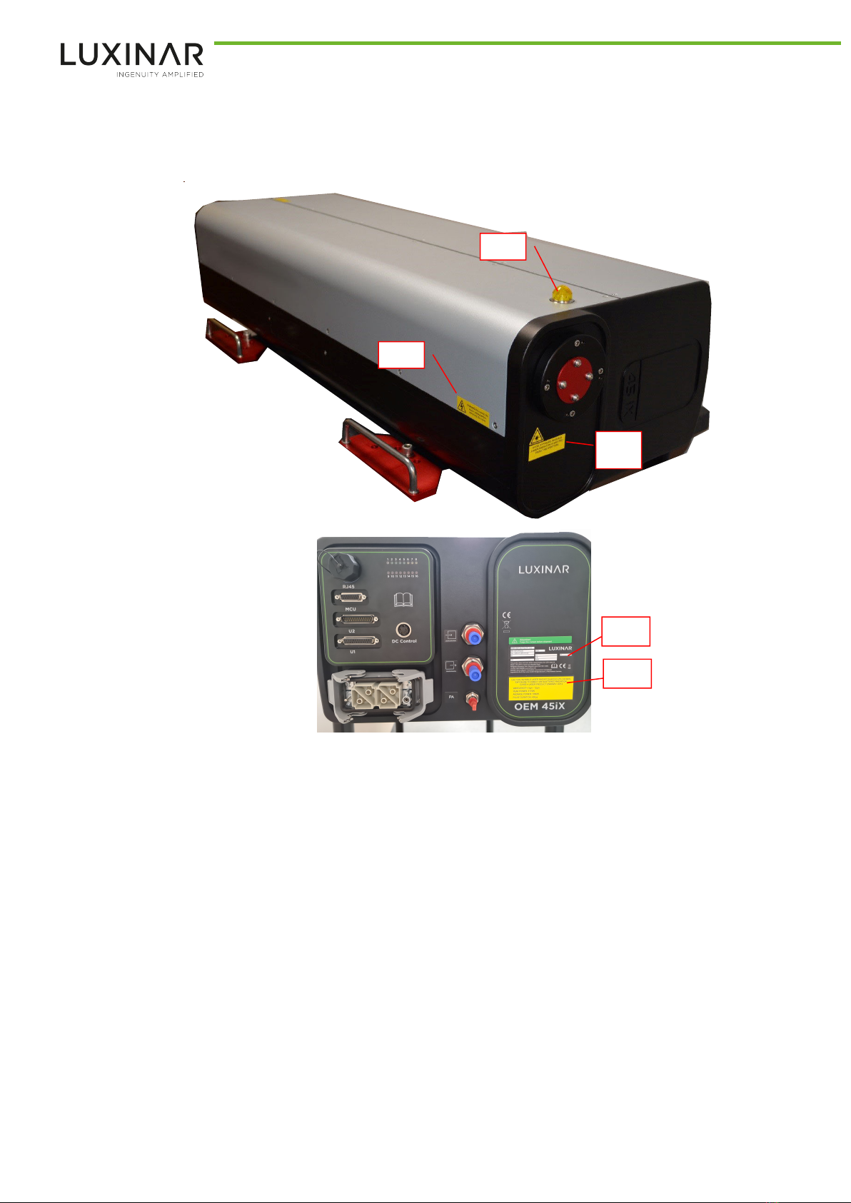
1.2. Label locations.....................................................................................................................................2
1.3. Labels.................................................................................................................................................. 4
1.4. Emission warning indicator................................................................................................................. 6
1.5. Maximum Permissible Exposure and Nominal Ocular Hazard Distance............................................. 6
1.6. Decommissioning and disposal........................................................................................................... 7
2. General description..................................................................................................................................... 9
2.1. Principle of operation..........................................................................................................................9
2.2. Laser head — Standard version...........................................................................................................9
2.3. OEM 45iX three-phase DC power supply (005-0547-00).................................................................. 11
2.3.1. General description.................................................................................................................... 11
2.3.2. Specification............................................................................................................................... 11
2.3.3. Installation..................................................................................................................................12
2.3.4. Operation................................................................................................................................... 15
2.3.5. Troubleshooting......................................................................................................................... 15
2.4. OEM 45iX three-phase DC power supply (016-0034-00).................................................................. 17
2.4.1. General description.................................................................................................................... 17
2.4.2. Specification............................................................................................................................... 17
2.4.3. Installation..................................................................................................................................18
2.4.4. Operation................................................................................................................................... 21
2.4.5. Troubleshooting......................................................................................................................... 21
2.5. Absorbing Thin Film Reflector (ATFR)/circular polariser................................................................... 22
2.5.1. Back reflection considerations................................................................................................... 22
2.6. Specifications.................................................................................................................................... 22
2.6.1. RF power supply......................................................................................................................... 23
2.6.2. Dimensions................................................................................................................................. 23
2.6.3. Weights...................................................................................................................................... 23
2.6.4. Customer connections............................................................................................................... 23
2.6.5. Cooling system........................................................................................................................... 23
2.6.6. Optics purge gas......................................................................................................................... 24
2.6.7. Environmental specifications..................................................................................................... 25
2.6.8. Performance...............................................................................................................................25
2.6.9. Laser diode pointer option......................................................................................................... 26
3. Operation...................................................................................................................................................27
3.1. Overview of control options..............................................................................................................27
3.1.1. Hand-held MCU (Mobile Control Unit).......................................................................................27
3.1.2. Host machine commands using the U1 connector.....................................................................28
3.2. General considerations before starting the laser..............................................................................28
3.3. Start-up............................................................................................................................................. 28
3.4. Shutdown.......................................................................................................................................... 29
3.5. Emergency stop................................................................................................................................. 29
4. Diagnostics and troubleshooting.............................................................................................................. 31
4.1. Laser and RF power supply................................................................................................................31
5. Routine maintenance................................................................................................................................ 35
5.1. General cleaning................................................................................................................................35
906-0237-00 REV 6 i Table of contents

5.2. Safety shutter.................................................................................................................................... 35
5.3. Purge gas filter.................................................................................................................................. 35
5.4. Cooling system contamination.......................................................................................................... 36
5.5. Frost protection.................................................................................................................................37
6. Installation................................................................................................................................................. 39
6.1. Installation procedure overview....................................................................................................... 39
6.2. Unpacking, mounting and connections.............................................................................................40
6.2.1. Unpacking...................................................................................................................................40
6.2.2. Lifting techniques and precautions............................................................................................ 40
6.2.3. Mechanical fixing........................................................................................................................41
6.2.4. Laser output aperture location.................................................................................................. 43
6.2.5. Coolant connections and pipework............................................................................................44
6.2.6. Beam delivery optics purge gas..................................................................................................45
6.2.7. Luxinar DC power supply............................................................................................................ 46
6.2.8. Luxinar DC power supply connections....................................................................................... 47
6.2.9. OEM-sourced DC power supply..................................................................................................48
6.2.10. DC cabling................................................................................................................................. 48
6.2.11. DC connectors.......................................................................................................................... 49
6.2.12. Beam delivery system.............................................................................................................. 50
6.2.13. Absorbing Thin Film Reflector (ATFR)/circular polariser.......................................................... 51
7. Transport and recommissioning............................................................................................................... 53
8. Interfacing..................................................................................................................................................55
8.1. Standard interface.............................................................................................................................55
8.2. SCX 30 emulation mode interface..................................................................................................... 61
8.3. Connector U2 —all modes................................................................................................................ 65
8.4. Connector U1 — standard connections for laser output.................................................................. 67
8.4.1. Minimum connections — internal PWM mode......................................................................... 67
8.4.2. Minimum connections — Auto mode........................................................................................ 67
8.4.3. Auto mode timing...................................................................................................................... 68
8.4.4. Minimum connections — external PWM mode.........................................................................70
8.4.5. Connector U1 SCX 30 emulation connections for laser output..................................................70
Appendix A. Acoustic zones.......................................................................................................................... 71
Appendix B. Dimensional drawings.............................................................................................................. 73
Appendix C. Coolant requirements and additives........................................................................................75
C.1. Coolant quality.................................................................................................................................. 75
C.2. Suspended particle removal..............................................................................................................75
C.3. Corrosion and anti-bacterial inhibitor............................................................................................... 75
Appendix D. Cooling system pressure drop curve........................................................................................77
Appendix E. Parts list.....................................................................................................................................79
Appendix F. Applications troubleshooting................................................................................................... 81
F.1. Common issues..................................................................................................................................81
F.2. Causes and corrective actions........................................................................................................... 83
Table of contents ii 906-0237-00 REV 6

Preface
Audience
This manual should be read by all personnel who install or operate OEM 45iX lasers.
Important!
Read this manual carefully before operating the laser for the first time. Pay special attention to
the Safety chapter.
The OEM 45iX is designed and sold for use in Original Equipment Manufacturer (OEM) systems and is
not to be used as a stand-alone laser. The OEM is responsible for compliance with all applicable safety
regulations.
Other publications
• Luxinar part number 906-0251-xx-00; Safety manual
• Luxinar part number 906-0109-00; Serial interface specification
• Luxinar part number 906-0104-xx; Optical isolation (ATFR)
• Luxinar part number 906-0202-99; Chiller coolant temperature tables
How to use this manual
The following conventions are used in this manual.
Admonitions
The use of controls, replacement parts, adjustments, or procedures other than those specified within
this manual may result in exposure to any of these hazards.
• Laser hazards
• Electrical hazards
• Environmental hazards
• Mechanical hazards
The degree of seriousness of the hazard is indicated by the use of the following signal words:
DANGER
Indicates an imminent hazard which, if not avoided, is extremely likely to result in death or serious
injury.
WARNING
Indicates a potentially hazardous situation which, if not avoided, could result in death or serious
injury.
CAUTION
Indicates a potentially hazardous situation which, if not avoided, may result in minor or moderate
injury. It is also used to alert the user against unsafe working practices and potential damage to the
equipment.
Connector labels and signal names
Connector labels and signal names are shown in bold serif font to aid identification.
For example; RF Enable, external interlock
906-0237-00 REV 6 iii Preface

Preface iv 906-0237-00 REV 6

1. Safety
1.1. General safety information
It is strongly recommended that any personnel who are involved with the installation, operation or
maintenance of this laser equipment should first read and fully understand the contents of this manual
and Safety manual 906-0251-xx.
If there are any questions or doubts on any of the safety aspects of the equipment, then do not hesitate
to contact your nearest Luxinar Aftersales office or distributor for advice before proceeding.
The installation, operation, maintenance and repair of this laser equipment must only be carried out by
Luxinar service personnel or trained staff who have received correct instruction concerning the hazards
associated with this particular equipment.
Important!
All safety critical instructions contained within this document are framed with a border and
identified by CAUTION, WARNING or DANGER depending on the severity of the risk involved. In
addition, the safety symbol indicates that care should be taken when working with or on the
laser equipment.
Luxinar does not accept liability for any damage or injury howsoever caused or arising.
The symbol given below is also used on the equipment and indicates that the user should refer to the
OEM equipment operator’s manual for more information on the safe operation or installation of the
equipment.
906-0237-00 REV 6 1 1. Safety

1.2. Label locations
Version with covers
A1.3
A1.1
A1.5
A1.8
A1.7
A1.2
Figure 1 - Location of safety labels - version with covers
1. Safety 2 906-0237-00 REV 6

Version without covers
A1.2
A1.7
A1.4
A1.3
A1.1
A1.9
Figure 2 - Location of safety labels — version without covers
906-0237-00 REV 6 3 1. Safety

DC PSU
A1.5
A1.7
A1.1
A1.6
Figure 3 - Location of safety labels — 005-0547-00
A1.7 A1.6
A1.11
Figure 4 - Location of safety labels — 016-0034-00
1.3. Labels
Figure 5 - Label A1.1 — Laser hazard
Figure 6 - Label A1.2 — Output specification without diode option
1. Safety 4 906-0237-00 REV 6

Figure 7 - Label A1.2 — Output specification with diode option
AVOID EXPOSURE INVISIBLE
LASER RADIATION IS
EMITTED FROM THE APERTURE
Figure 8 - Label A1.3 — Laser aperture without diode option
AVOID EXPOSURE INVISIBLE AND
VISIBLE LASER RADIATION IS
EMITTED FROM THE APERTURE
Figure 9 - Label A1.3 — Laser aperture with diode option
Figure 10 - Label A1.4 — Non-interlocked panel without diode option
Figure 11 - Label A1.4 — Non-interlocked panel with diode option
WARNING
Disconnect the mains supply
before removing this cover
Figure 12 - Label A1.5 — Mains supply warning
Figure 13 - Label A1.6 — 50V DC
906-0237-00 REV 6 5 1. Safety

Figure 14 - Label A1.11 — High leakage current
7
5
1
2
3
4
6
1Model number
2Part number
3Serial number
4Input
5Revision
6Weight
7IP rating
Figure 15 - Label A1.7 — Product identification and certification
1.4. Emission warning indicator
An emission warning indicator is fitted to the laser head cover adjacent to the output aperture, shown
as A1.8 in Figure 1 and A1.9 in Figure 2. When the indicator is illuminated, the laser is capable of
emitting harmful laser radiation.
DANGER
Risk of injury to eyes and exposed skin
This is a Class 4 (Class IV) laser product. All precautions relevant to this class of laser product
should be strictly observed. Use of controls or adjustments or performance of procedures other
than those specified herein may result in hazardous radiation exposure. Strict compliance with
the safety precautions set out and referred to in this manual and extreme care in use are
essential to minimise the chance of accidental damage to the equipment or personal injury.
Luxinar does not accept liability for any damage or injury howsoever caused or arising.
1.5. Maximum Permissible Exposure and Nominal Ocular Hazard Distance
The Maximum Permissible Exposure (MPE) is the level of radiation to which, under normal
circumstances, persons may be exposed without adverse effects. The MPEs represent the maximum
level to which the eye or skin can be exposed without consequential injury and are related to the
wavelength of the laser radiation, the pulse duration or exposure duration, and the tissue at risk.
The MPEs given in the following tables are informative and provided so that the integrator can calculate
the Nominal Ocular Hazard Distance (NOHD), perform a risk analysis and inform the user about the safe
usage of the product. However, exposure limits for the eye and the skin of employees in the work place
1. Safety 6 906-0237-00 REV 6

and the general public are in many countries specified in national laws. These legally-binding national
exposure limits might differ from the MPEs given in the tables below.
The NOHD is the distance from the output aperture beyond which the beam irradiance or radiant
exposure remains below the appropriate MPE. Importantly, the NOHD is dependent upon the beam
waist size and the divergence of the beam. Therefore, the NOHD is dependent upon the optical
components acting on the beam. The NOHDs given in the tables below are relevant only when the laser
is operated without external beam delivery attached. When beam delivery is attached it is the
responsibility of the integrator or end-user to recalculate the NOHDs. Further details of the safe use of
lasers are given with IEC/ TR 60824-14 "Safety of laser products – Part 14: A user’s guide."
Wavelength (µm) 10.6 10.25 9.3
MPE (W/m²) 1000 1000 1000
NOHD (m) 1400 1400 1500
1.6. Decommissioning and disposal
Dispose of the system according to appropriate local regulations.
906-0237-00 REV 6 7 1. Safety

1. Safety 8 906-0237-00 REV 6

2. General description
2.1. Principle of operation
1Output laser beam
2Output window
3Resonator output mirror
4Coolant out
5Radio frequency input electrode
6Coolant in
7Resonator rear mirror
8Gas discharge (active laser medium)
9Wave guide electrodes
10 Ground electrode
Figure 16 - Diffusion cooled slab laser components
Figure 16 shows the principle of operation of a slab laser. A gas discharge (8) forms the active laser
medium and is established between the wave guide electrodes (9) by a radio frequency voltage (5, 10).
The rear mirror (7) and output mirror (3) form the optical resonator. The laser beam (1) is produced
within the resonator and is emitted through an output window (2). Liquid coolant flowing between the
input (6) and output (4) is used to cool the electrodes.
2.2. Laser head — Standard version
The OEM 45iX laser is a high-frequency excited, diffusion-cooled CO2 slab laser designed for industrial
use as a cutting, welding or marking tool. It comprises a laser resonator assembly with integrated RF
power supply and a hand-held Mobile Control Unit (MCU).
It is available with or without covers.
906-0237-00 REV 6 9 2. General description

Figure 17 - OEM 45iX with covers
Figure 18 - OEM 45iX without covers
2. General description 10 906-0237-00 REV 6

2.3. OEM 45iX three-phase DC power supply (005-0547-00)
2.3.1. General description
Note: This equipment is designed for indoor use only, pollution degree 2 and overvoltage category II as
defined within EN 61010-1:2010+A1:2019.
The OEM 45iX three-phase power supply is a 3U, 19” rack mountable, AC to DC liquid-cooled power
supply (PSU).
Figure 19 - OEM 45iX three-phase DC power supply
2.3.2. Specification
WARNING
Heavy equipment — risk of severe lumbar injury
The weight of the DC power supply exceeds the single person lift limit of 18kg, as specified in
EN 61010-1:2010+A1:2019. Ensure a minimum of two people lift the power supply or that
suitable lifting equipment is employed.
Table 1 - Dimensions, weight and cooling
Dimensions (mm) LxWxH 633x483x133
Weight 24kg
Coolant type Demineralised, deionised or distilled water with
corrosion inhibitor & anti-bacterial additive
Coolant pipe 10mm OD
Coolant flow rate Refer to section 2.6.5
Pressure Maximum 90psi (6bar)
Protection class IP51
906-0237-00 REV 6 11 2. General description

Figure 20 - Overall dimensions
Table 2 - Electrical specifications
OEM 45iX
Input voltage range 400VAC ± 10% (50/60Hz) three-phase (1)
Mains input fuse rating (per phase) 20A
AC inrush current (max) 50A
Output voltage (DC) 50 ± 2%
Output current 200A
Power factor >0.90 at full power
Power consumption (max) 10kW at full power
Earth leakage current <6mA
Important!
An external disconnect device must be fitted at the time of installation, and must be accessible
without needing to use a tool. This must be suitably located and easily reached and must be
marked as the disconnecting device for the power supply.
2.3.3. Installation
Mechanical installation
Using suitable fasteners, mount the power supply within the OEM machine racking using the four
mounting holes shown in the following figure.
Figure 21 - Fixing locations
Mains AC power connections
Important!
Under certain conditions, it may be possible for high voltage and current cables to emit noise
energy levels that may interfere with control signal cables. To eliminate the possibility of
interference, cables carrying control signals should be routed along a different path to power
cables.
1. No neutral connection is required. Connection to neutral will cause irreparable damage to the power supply.
2. General description 12 906-0237-00 REV 6
Table of contents
Other Luxinar Measuring Instrument manuals
Popular Measuring Instrument manuals by other brands

PCB Piezotronics
PCB Piezotronics IMI SENSORS 605B61 Installation and operating manual

MEET Technology
MEET Technology MS-911 quick start guide

CONDTROL
CONDTROL Paint PRO user manual

Troxler
Troxler 3440-L Manual of Operation and Instruction

Munro Sonic
Munro Sonic EGG100 Operation manual

Huberth
Huberth RP202099 quick start guide