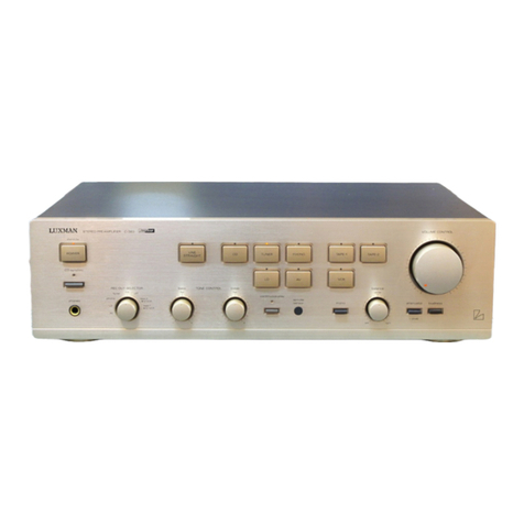
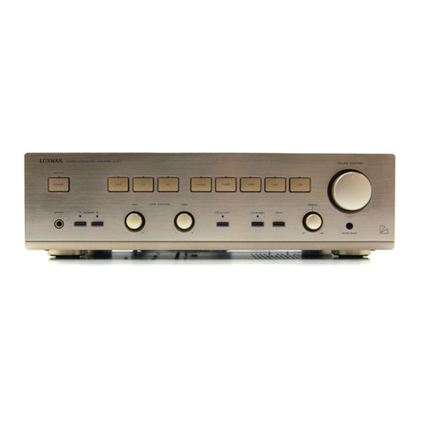
Luxman R-1070 User manual

SERVICE
MANUAL
-
AM/FM
STEREO
=]
1070
DC
TUNER-AMPLIFIER
@
Om
|
SO
ae
SE
a
Ee
a
ee
a
ee
en

SARTO
REC
INERSIRT
Ot
as
Hie
ORL
eS
SERRE:
svrinaare
Nasa
sea?
Lis
seetcets
$<
wea
nae.
SRM:
12
Marve
ere
RRA
48
4
Bent
scistisdesdacp
Mak
stkeidaart
cot
Wdadibancsd
SHS
HERRING
te
Peat
Sees
Petpoeet
STR
Fa
BPR
GS
abe
Ritmhen
BG
CE:
eM
Pe
eke
MEAGRE.
GUOREG
1
et
RUT
GETTER,
SNGR'
A
Gan
yaee
Meee
anaes
rex
HARE
REE
aR
Sis
SNE
IRAE
OR
SE
PAROGY)
ION
IER
cuueNe
FER
SHIR
sed
eset
roe
Pesce
es
de
$58
Bi
Get
oe
Mies
TR
Se
es
eRe
SRR
0S
SR
BberLses
13
tony
j
Vier
Ax
Gta
RATE
RIRRED
Bache
hy
da
|
PROMEL
FOE
IAS
3K

R1070
ALIGNMENT
PROCEDURE
(RF
Section)
otep
Process
1.
Connection
Connect
the
"REC
out"
terminal
at
the
back
panel
with
the
milli-volt
meter,
distortion
meter,
and
synchroscope.
Also
connect
the
FM
SG
(FM
Signal
Generator)
and
stereo
signal
operator
to
the
FM
antenna
terminal.
Set
each
control
on
the
front
Senes
Function
switch
at
the
"FM"
position.
IF
selector
at
the
"wide"
position.
Muting
switch
at
the
"off"
position.
Dolby
FM
switch
(if
provided)
at
the
"off"
position.
Set
the
semi-fixed
volumes
on
the
RF
board
as
follows.
center
O)
VR106
endmost
é
VRIO5
©)
CO)
center
C)
VRI08
VRI01
VR102
center
center
C)
center
C)
C)
VR1I04
VR103
center
center
VRIIO1
3.
Frontend
and
IF
Alignment
cu
oa
GQ
.
:
Confirm
the
de-emphasis
:
S
type
50uS,
U
type
7/5uS
Confirm
that
the
dial
pointer
starts
at
the
correct
point
and
moves
smoothly
on
the
dial
plate.
Set
the
dial
pointer
at
the
point
having
no
broadcast
station
and
receive
an
inter-station
noise.
Adjust
the
T1902
to
read
"0"
on
the
center
pSREe.
Set
the
FM
SG
to
108MHz,
output
1lmV,
mono
400Hz
100%
modulation.
Set
the
dial
pointer
at
108MHz
to
obtain
400Hz
signal
at
the
REC
out
terminal.
Reduce
the
output
of
FM
SG,
and
confirm
that
noise
is
overlapped
symmetrically
on
the
output
wave-form
of
400Hz.
Reduce
the
output
down
to
about
iSuvy
Adjust
the
trimmer
of
oscillator
to
receive
the
above
signal
correctly.
Adjust
the
antenna,
3
inter-stage
trimmers
at
the
frontend
one
by
one
to
obtain
the
maximum
output
at
the
REC
out
terminal.

i.
Set
the
FM
SG
to
87.5MHz,
output
1.5uV,
mono
400Hz
100%
modulation.
j.
Set
the
dial
pointer
at
87.5MHz,
and
confirm
that
above
signal
is
received
within
the
width
of
the
dial
pointer.
k.
Repeat
the
steps
(d)-(j)
2
or
3
times
to
obtain
the
max.
sensitivity
and
the
min.
dial
calibration
error.
Then,
adjust
the
frontend
IFT
L1005
to
get
the
max.
output.
1.
Set
the
FM
SG
to
98MHz,
output
20uV,
1KHz
100%
modulation,
and
adjust
the
VR104
to
obtain
the
swing
of
the
signal
strength
meter
at
"0.7".
m.
Change
the
output
to
lmV,
and
adjust
the
VR105
to
obtain
"4.5"
reading
on
the
signal
meter.
Then
switch
off
the
FM
SG
and
confirm
that
the
signal
meter
shows
the
zero
position.
n.
Set
the
IF
selector
switch
at
the
"narrow"
position,
and
adjust
the
VR1O1
as
per
the
step
(m).
o.
Increase
the
output
of
FM
SG
gradually
in
the
order
of
20uV,
500uV
and
IlmV,
and
confirm
that
no
change
takes
place
in
the
signal
strength
meter
by
inter-switching
the
IF
selector
between
the
"narrow'
and
"wide"
positions.
p.
Set
the
IF
selector
at
the
"wide"
position
and
fix
the
output
of
FM
SG
at
10uV.
Then
turn
on
the
muting
switch,
and
adjust
the
VR1O8
at
the
point
where
the
output
signal
is
available
at
the
REC
out
terminal.
q.
Set
the
FM
SG
to
ImV
output,
400Hz
100%
modulation,
and
adjust
the
T101
to
obtain
the
minimum
distortion.
r.
Reduce
the
FM
SG
output
to
the
minimum,
and
adjust
the
T102
to
obtain
the
"0"
indication
of
the
pointer
at
the
center
meter.
s.
Repeat
the
steps
(q)
and
(r).
4.
FM
MPX
Alignment
a.
Set
the
FM
SG
to
ImV
output,
no
modulation.
b.
Connect
a
frequency
counter
at
the
pin
No.
112
and
adjust
the
VR103
to
obtain
76KHz
ae
Hz
on
the
frequency
counter.
c.
Set
the
FM
SG
to
lmV
output,
1KHz
100%
stereo
modulation.
d.
Adjust
the
VR10O7
to
obtain
the
balanced
max.
separation
between
the
right
and
left
channels.
e.
Adjust
the
VR102
to
get
the
minimal
distortion.
f.
Confirm
that
the
stereo
indicator
lights
up.
g.
As
the
last
step,
adjust
the
VR1101
to
obtain
1V+10%
at
the
REC
out
terminal.
5.
Anti-birdie
Alignment
(S
type
only)
a.
The
anti-birdie
filter
does
not
need
adjustment
in
principle,
and
confirm
only
the
frequency
response.
b.
The
output
of
the
anti-birdie
filter
:
I1KHz
OdB
60KHz
-O0O.5dB
7
OKHz
-11dB

6.
AM
Section
a
b.
‘)
Ou
Set
the
AM-FM
switch
to
AM
position.
Connect
the
output
of
455KHz
Sweep
Generator
(SPG)
to
the
No.
130
terminal.
Connect
the
SPG
input
to
the
No.
129
terminal.
Set
the
SPG
to
“output
40-50dB,
sweep
speed
5-10Hz"
:
Adjust
the
T104
and
T105
so
that
the
IF
wave-form
can
be
symmetrical
and
that
the
output
can
be
maximum.
It
is
suggested
that
the
dial
pointer
sets
to
the
1,600KHz.
.
Disconnect
the
SPG.
Tune
in
to
600KHz
and
1,400KHz
on
the
dial
scale
by
adjustment
of
the
local
OSC
trimmer
and
core.
;
Adjust
the
bar-antenna
and
the
antenna
trimmer
to
obtain
the
maximum
output
of
tuner
at
600KHz
and
1,400KHz.
Set
the
output
of
AM
SG
at
100dB/m
and
adjust
VR106
so
that
the
signal
strength
meter
swings
to
4
1/2.
(ANT-IN
100dB/m)
i
SS
Net
die
es
te
Se!
a
oe
Ee
get
asi
We
aA
Cone
Wier

EXPLODED
VIEW
R-1070
EXPLODED
VIEW
PARTS
LIST
1.
WB1063
Wooden
Case
|
23.
SROO83
Rotary
Sw
(SP
Select)
2.
UR1125
Fixing
Metal
—
24.
TDO149B
LED
LDOO2RB
x
4
ce
Screw
4x20
TDO150B
LED
LDOO3RB
x
4
4.
Bx0040
Dial
Drum
25.
UR1141
Fixing
Metal
5.
AM0040
Signal
Meter
26.
Screw
4x10
6.
AM0039
Tuning
Meter
27.
WJ1066
Mould
Knob
(Power)
7.
Screw
4x10
black
28.
UB1033
Sub
Panel
8.
SRO111
Rotary
Sw
(Input
Select.)
29.
SP0113
Push
Sw
(Power)
(U)
9.
RVO103
Bass
Control
100kB
SP0114
Push
Sw
(Power)
(E)
{(S)
10.
RVO096
Treble
Control
50kB
30.
WJ1069
Mould
Knob
x
9
11.
WJ1067
Mould
Knob
(mode,
dubbing)
31.
SROO87
Rotary
Sw
(Mode)
12.
UXx1003
Fly-Wheel
32.
SROO88
Rotary
Sw
(Dubb.)
13.
RVO094
Main
VR
50kBx2+100kBx2
33.
PT2332
Power
Transformer
(E)
14.
Wi1045
Dial
Scale
PT2334
Power
Transformer
(VU)
15.
WH1033
Knob
(Input
Select.)
PT2335
Power
Transformer
(S)
16.
WH1039
Knob
(Tone
Cont.)
34.
LA1908
Frontend
17.
WH1039
Knob
(Tone
Cont.)
--
UC1107
Rear
Panel
(E)
(U)
18.
WH1035
Knob
(Tuning)
UC1108
Rear
Panel
(S)
19.
WH1039
Knob
(Main
VR)
--
BU0069
Leg
20.
WH1033
Knob
(SP
Select.)
--
BE1063
Heat
Sink
21.
WA1L140
Front
Panel
--
SP0077
Push
Sw
(Muting,
Monitor
etc)
22.
AJO0015
Headphone
Jack
--
§P0076
Push
Sw
(Filters)

Replacement
Parts
List
ee
ee
ee
ee
ee
ee
ee
ee
Qe
re
ee
ee
Remarks
Capacitors:
C.....
Ceramic,
Bigcieeans
Electrolytic,
Mize
tes
Mylar,
Goh
5.8%
G
Capacitor
ae
Styrol,
Peete
Tantalum,
Mis
oeMiea,
MP....MP
Capacitor
Osi40e0Ll
capacitor,
TRIMS
32.6
Trimmer
capacitor,
AC....AC
Capacitor
BP....Electrolytic
Bi-Polar
type
Resistors:
+10%,
+5%,
1/4W,
unless
specified
otherwise
Type:
op
eer
Model
for
north
European
countries
Citing
Stee
Model
for
U.S.A.
and
CANADA
Cito
ae
Standard
model
ie
eae
Model
for
JAPAN
CEO079
|
220uUF
+50%
CKO158
|0.047uF
+807
CKO158
|0.047uF
+807
0.047uF
+80%
0.047uF
+80%
0.047uF
+80%
22uF
+50%
0.022uF
+80%
.O22uUF
+80%
.OOLUF
+20%
.O47uF
+80%
.022uUF
+807
.OO1LUF
+202
10uF
+507
3.3uF
+752
O0.01uF
+80%
0.018uF
+107
QO.022uF
+10%
0.0012uF
+107
220uF
+50%
0.047
+80%
10uF
+50%
0.022uF
+80%
O.47uF
+75%
CCO002
+10%
-102
CE0074
+50%
-102
CKOL58
:
+80%
-202%
CKO158
;
+80%
-204
C02
tf
Oo)
+80%
-20%
+80%
-20%
+80%
-202
+80%
-202
CKO155
CKO158
CKO158
CKO158
Oooo
a
ee
be
+80%
-20%
+80%
-207%
+80%
-202%
+80%
-202
+80%
-202%
+10%
-102
+80%
-202%
CKO155
+80%
-202
CKO158
+80%
-20%
CKO158
|.
+80%
-202
CKO158
:
+80%
-202%
CKO158
‘
+80%
-20%
CKO158
:
+80%
-202
CKO158
.
+80%
-20%
CC0007
+10%
-107
CQ0079
+
5%
-
52
CQ0009
;
+10%
-10%
CQ0079
+
5%
-
54
CEO168
:
+75%
-10%
CEO095
+75%
-10%
cso0o19
"
+20%
-20%
CEO099
‘
+75%
-10%
CE0099
;
+75%
-10%
CKO155
.
+80%
-20%
CK0158
:
+80%
-20%
CKO155
:
+80%
-20%
CKO155
:
+80%
-20%
CKO158
:
+80%
-20%
CKO1L58
:
+80%
-20%
CKO155
F
+80%
-20%
CE0099
:
+754
-192
CKO158
.
+80%
-20%
CKO158
.
+80%
-20%
CKO158
.
+80%
-20%
CE0099
;
+75%
-10%
CE0079
+50%
-10%
CKO155
CKO158
CKO158
CKO158
'1CKO158
CCO130
CKO155
oOoonooo0ce
HORRORS
SS
OMRM
OO
AeA
OH
OOD
OO
+20%
-20%
+75%
-10%
+20%
-202%
+50%
-102%
+75%
-102%
+
5%
-
54
+
54
-.52%
ONnNMAAAmH
NH
+75%
-10%
+
5%
-
5%
+
5%
-
5%
+50%
-10%
+80%
-20%
+50%
-10%
+50% -10%
+50%
-10%
+50% -10%
+50% -10%
+80%
-20%
+80% -20%
AMOAO
OMANI
AAAAAMMHAMANEANAAARAANDAAARAAAANAANAAANAN
CCcO013
+10%
-102%
CQ0172
+
54
-
52%
cco004
+10%
-102%
CKO158
:
+80%
~20%
QAaomnnwtrmAm
ON
WN
OnwMnnqa

SYMBOL
|
STOCK
LOCA-
CKO155
|0.0luF
+80%
-20%
50V
Cg0218
|
750pF
+
5%
-
5%
SOV
CQ0218
|
750pF
+
5%
-
5%
5OV
CKO155|0.01uF
+80%
-20%
50V
CEOO74
|
1LOUF
+50%
-10%
16V
CKO153
|
0.047uF
+80%
-20%
25V
AQmAoInng
CEO075
CEQ075
CKO109
CE0213
CKO158
22uF
+50%
-10%
16V
22uF
+50%
-10%
16V
470pF
+10%
-10%
50V
2.2uUF
+75%
-10%
50V
O.047uF
+80%
-20%
25V
Omo
fi
tf
1082
47K
1K
RBO134
RBO222
RBO182
LOK
x
2
4702
47K
RBO206
RBO174
RBO222
RBO174
RBO200
RBO158
RBO1/0
RBO182
RBO206
RBO158
RBO174
RBO1/0
RBO198
RBO222
RBO166
RBO176
RBO198
RBO182
RBO166
RBO182
RBO134
RBO172
RBO202
RDO026
RBO166
RBO158
RBO1L58
RBO206
4702
5.6K
1002
3302
1K
10K
1002
4702
330
4.7K
47K
2202
5602
4.7K
1K
2202
1K
1082
3902
6.8K
R
1/4
22K
2202
£002
1002
10K
J
LOOK
1K
4702
6802
3.3K
3.3K
1K
3.3K
3.3K
3.3K
3.3K
22K
22K
10K
RBO230
RBO182
RBO174
RBO178
RBO194
RBO194
RBO182
RBO194
RBO194
RBO194
RBO194
RBO214
RBO214
RBO206
RBO230
RBO222
RBO148
RBO230
RBO200
SYMBOL
|
STOCK
LOCA-
1K
Y1
RBO182
RBO210
RDOO29
RBO182
RBO206
RBO174
RBO170
RBO198
RBO198
RBOQ222
RBO166
RBO176
RBO158
RBO218
RBO218
RBO206
RDOO043
RDO222
RDOO39
RDO069
RBO222
RBO208
RBO134
RDOO41
RBO1/0
RBO206
RBO206
RBO192
RBO216
RBO234
RBO216
RBO172
RBO184
15K
12K
R1/4
1K
7
10K
470
330
4.7K
“eK
47K
220
560
100
33K
33K
10K
R
1/4
1K
47K
R
1/4
2.2K
R
1/3
10
47K
12K
10
R
1/4
1.5K
330
10K
10K
2.7K
27K
150K
27K
390
1.2K
RBO222
RBO222
RBO230
RBO230
RBO206
RBO218
RBO206
|
RBO218
RDO0039
RBO0218
RDO260
RDOOS51
RBO182
RBO188
RBO218
RBO200
RBO190
RBO210
RBO216
RBO158
47K
47K
100K
100K
10K
33K
LOK
33K
R
1/4
2.2K
33K
R-50
270
R
1/4
270
1K
1.8K
33K
5.6K
2.2K
15K
27K
100
RBO206
RBO206
RB0206
RBO198
RBO206
RBOL58
10K
LOK
10K
4.7K
10K
100

TRO2
33
TROO85
TROO85
TROO85
TROO85
TROO85
TRO198
TROO25
TRO121
TRO198
TRO198
TROO25
TRO198
TCO106
TCOO099
TCO100
TCOO21
TC5006
TDO116
TDO116
TVO0004
TDO116
TDO018
TDOO18
TDO116
TDO079
TDO116
TDO116
TDO137
as
ei
LOCA-
28C535
2801923
Z5C1923
2501923
Z9C1923
29G1923
2SC1815
2SC1345
2SC1626
2SC1815
2SC1815
2SC1345
2SC1815
uUPC1163H
LA1231
uPC1173
HA1197__—.
uPC4558C
152/05
182705
KB265
IS2705
1K188-FM1
1K188-FM1
152705
WZ140
182705
182705
SIVBIO
agichar
3W3N
NG
maisn
NN
uNe
OVINE
LOLs
(L)V4OES
AOSZ
AINO
35N4
a
adAL
3AvS
binaith
sov71d3u
fe
Se
oe
=
SOue
JOLLUA

PB1228
SYMBOL
STOCK
|
LOCA-
emi
DESCRIPTION
TION
SYMBOL
|
STOCK
LOCA-
TION
Y2
RS1586
RS1568
RSOO74
RDO062
RDO259
RSO067
RDOO40
RDO047
RDOO45
RDOO45
RS1556
RS1556
RDOO21
RDOO21
RDO037
RDOO037
RGOOO1]
RGOOOL]
RS1534
RS5004
RSO201
RS5005
RDOO14
RDO034
RDO043
RDO032
RDO043
RDOO037
F50
1.5K
F50
270
F50
100
39
R50
47K
F1/4
150
1.8K
560
820
820
F50
220
F50
220
56K
56K
Sa
3K
3.9K
0.33
S5WCS
0.33
SWCS
F50
10
10
2W
4.7
2W
680
2W
180K
5.6K
1K
8.2K
1K
DEOK
X3
X1
X20
%2
YZ
-%2
Y22%2
X3
X1
X3
Xl
X32
XL
X3
X1
po
PG
X3
X1
X3
X1
X3
X1
X3
XL
X3
Xl
X3
Xl
X3
X1
X3
K1
X3
Xl
X3
X1
X2
K2
X2
X2
AZ,
RZ
X2
X2
X2
X2
CE5019
|1uF
+75%
5OVECX
X2
RS1092
|
F1/4
2.2K
CCO007
|100pF
+10%
-10%
50V
S
X2
X2
RDOOO4
|
1M
CEO085
|33uF
+50%
-10%
25V
E
X2
X2
RDOOO4
|
1M
CEO102
|47uF
+50%
-10%
50V
E
X2
X2
RDO023
|
39K
CQO0611
|0.22uF
+10%
-10%
100V
P
X2 X2
68K
CC0038
|5pF
+10%
-10%
50V
S_
X2
X2
RDOO39
|
2.2K
CQ0180
|33pF
+
5%
-
5%
125V
S
X2
X2
CKO183
|0.001luF
+10%
-10%
50V
S_
X2
X2
RDOO25
|
27K
CKO126
|0.00luF
+20%
-20%
50V
S
Y2
Y2
RDOO25
|
27K
CEO107
|47uF
+50%
-10%
63V
E
X2
X2
TRO146
|
2SC1740
CQ0124
|0.022
+
5%
-
5%
50V
M
X3
Xl
TRO146
|
2SC1740
CE0077
|33uF
+50%
-10%
16V
E
X3
Xl
TR5003
|
2SA798G
CEO076
|33uUF
+50%
-10%
16V
E
X3
Xl
TRO218
|
2SA872
CKO109
|470pF
+10%
-10%
50V
S_
X3
Xl
TRO218
|
2SA872
CKO109
|470pF
+10%
-10%
50V
S_
X3
Xl
TROO9O
|
2SD756
CKO203
|0.01uF
+20%
-20%
500V
S
X3 Xl
TROO9O
|
2SD756
CQ0613
|0.1pF
+10%
-10%
100V
P
X2
X2
TRO197
|
2SB716
cg5008
|0.1uF
+10%
-10%
250V
P
X3
X1
TRO165
|
2SC1775
CEO096
|220u
+50%
-10%
25V
E
X2
TRO218
|
2SA872
CEO118
|47uF
+50%
-10%
25V
E
x?
TRO165
|
2SC1775
CE0079
|220uF
+50%
-10%
16V
E
yg
TRO241
|
2SA1006
CEO079
|220uF
+50%
-10%
16V
E
x2
TRO242
|
2SC2336
CEO086
|10uF
+50%
-10%
25V
E
x2
TRO269
|
2SB705
CEOO86
|10uUF
+50%
-10%
25V
E
X2
TRO270
|
2SD745
CKO073
+10%
-10%
500V
S
TROOOL
|
2SC734
RDOO22
TRO146
|
2SC1740
RDO038
TRO148
|
2SA826
RDO038
TRO146
|
2SC1740
RDOO25 TRO146
|
2SC1740
RDOO37
TRO165
|2SC1775
RDOO22
TRO165
|
2SC1775
RDO0039
TDO141
|
BZ-340
RDOO25
TVOOO4
|
KB265
RDO0026
TDO069
|
1N4448
RDO039
TDO069
|
1N4448
RDO029
TDO069
|
1N4448
RDO032
TDO069
|
1N4448
RDO023
TDOOO1
|
1N4002
RDO134
TDOOO2
|
1N4001
RDO032
TDO073
|
WG713
TDOO73
|WG713

4dr
-
508D
R579b
508
10

PB1229
11
SYMBOL
NO.
STOCK
NO.
CE0080
CEO110
CEO107
CEO110
CK0203
CU0013
Cu0813
CU0013
CuU0013
Cu0013
RDO127
RDO133
RDO020
RS3078
TDO098
TDO139
TDO106
TDO106
TDO106
TDO106
TDO106
TRO241
470uF
47uF
47uF
100UF
O.O01luF
O.O01UF
0.01uF
0.01uF
0.01uUF
0.01uUF
2e2K
560
68K
100
IN4758A
S1VB20
S3V40
S3V40
S3V40
S3V40
S3V40
2SA1006
DESCRIPTION
1/2
1/2
1/4
2W
FP
F201
250V
315maqp
F202
250V
315mA(D
“F203
250V
315mAD
“F204
250V
63
AQ
F205
250V
63
AD,

PB1230
C30lab
|
CE5025
CKO155
CE0078
CE5025
CQ0031
CQ0130
CQ0130
CQ0177
CE5025
CE0145
CE5019
CEO107
CEO107
RBO246
RBO254
RBO192
RBO212
RBO222
RBO212
RBO169
RBO192
RBO214
RBO192
RBO194
RBO194
RBO186
RBO212
RBO182
RBO212
RBO218
RBO246
RBO168
RBO200
RBO200
RS1230
RS1227
TRO125
TRO174
TRO125
TRO125
SYMBOL
|
STOCK
NO.
NO.
3.3uF
+75%
O.O0luF
+80%
100uF
+75%
3.
3uF
+75%
0.033uF
+
5%
0O.001luF
+
5%
0
0
3
.OO1UF
+
5%
.0027UF
+
52%
.3uF
+75%
390
1/4M
220
1/4M
2SA836
2SC1345
2SA836
2SA836
LOCA-
DESCRIPTION
-102
-202%
-102
~102
-
5%
-
5h
-
54
-
54
-102
%
5OVECX|
X2
S5OVECX]
X4
Y
50V
c
|
X3
16V
E
|X3
5OVEXC|
X3
Y3
50V
M
|
Y2
50V
M
{|
Y2
50V
M
|
Y2
50V
M
|
Y3
5OVECX]|
Y2
Y2
geleg
S.
7
Oh,
a.
:
GW)
4
@
*.
oO
12

PBL2Z31
SYMBOL
STOCK
NO.
DESCRIPTION
CKO146
+80%
CKO146
+80%
CE0250
+50%
CEO250
+50%
CKO146
|
0.
+80%
CKO146
|
0.
+80%
CKO146
|
0.
+80%
CKO146
|
0.
+80%
CQ0018
|
0.
+10%
CQ0018
|
0.
+10%
CKO146
|
0.
+80%
O72
2S
OOOO
EO
OO
RS2715
1WFP
RS2715
RS2715
RS2715
RS2527
RBO196
RBO210
RDO119
RDO119
RDO119
RDO119
RDO119
RDO119
RDO119
RDO119
RDO119
RDO119
RBO196
RBO210
RDO119
RDO119
RDO119
RDO119
RDO119
RDO119
RDO119
RDO119
RDO119
RDO119
RBO198
Ps
%
Oho
oF:
i
Sg
Bes
S094.
BWW
WW
W
W
WD
WWD
WF
DW
DW
WD
WW
Ww
WW
WwW
RBO202
|
6.
RBO208
RBO208
|
12K
TCO101
|
TA7318P-1
TCO102
|
TA7612P
TCO102
|
TA7612P
TDOOO2
|
1N4002
TDOOO2
|
1N4002
TDOO59
|
BZ192
TD5006
|
BZ130
TD5006
|
BZ130
TDOO60
|
WZ061
13

PB1232
|
PB1233
a
nes
LOCA-
ek
ig
LOCA-
RBO254
CQ0021
|0.0033uF
+10%
-10%
50V
M
RBO254
CQ0021
|0.0033uF
+10%
-10%
50V
M
RBO254
CQ0009
|0.047uF
+10%
-10%
50V
M
RBO0254
CQ0009
|0.047uF
+10%
-10%
50V
M
RBO200
CQ0006
|0.082uF
+10%
-10%
50V
M
RBO200
CQ0006
|0.082uF
+10%
-10%
50V
M
CE0099
|
2.2uF
+75%
-10%
50V
E
CEO099
|
2.2uF
+75%
-10%
50V
E
CKO113
|0.001luF
+10%
-10%
50V
C
ao
oR.
2
2
CKO113
|0.001uF
+10%
-10%
50V
C
EONS
ie
ee
ia
|
CEO099
|2.2uF
+75%
-10%
50V
E
=
—
CEO074
|
10uF
+50%
-10%
16V
E
CKO159
|
0.1
+80%
-20%
25V
C
CEOO78
|
100uUF
+50% -10%
16V
E
RBO254
RBO254
RBO254
RBO254
RBO202
RBO202
RBO200
RBO200
RBO216
RBO216
RBO218
RBO206
RBO222
RBO182
RBO198
RBO206
RBO230
RBO246
1M
R25
1M
R25
1M
R25
1M
R25
6.8K
R25
6.8K
R25
5.6K
R25
5.6K
R25
27K
R25
27K
R25
33K
R25
10K
R25
47K
R25
1K
R25
4.7K
R25
10K
R25
100K
R25
470K
R25
R706
Wor
|
gav-
-0
2S5C1740
25C1740
TRO146
TRO146
“HOLd
eS
~
RI04
TDOO16
{151555
LLL
60L
OLL
Wh
Uk
CRE
Wel
SUL
826
825
824
See
ee
aa
ee
816
815
814
813
B12
B11
:
oR@DaD
eww
“804
BD
aot
a
-
805
a
806
803.
808
|
809
PEAK
LNDICATER
~
poLbY
sw’
14

PB1064A
oo
—
LOCA-
CE5025
|3.3uF
+75%
-10%
SOVECX|Y1
X
CCOO005
|
33pF
+10%
-10%
50V
C
CEOO078
|100uUF
+50%
-10%
16V
E
O.001UF
+
5%
-
5%
50V
M
O.001uF
+
5%
-
5%
50V
M
0.0068uF
+
5%
-
5%
50V
M
10uF
+50%
-10%
50VENX
5pF
+0.5pF
-0.5pF
50V
C
1uF
+75%
-10%
50VECX
CQ0130
CQ0130
CQ0122
CE2040
Cc0037
CE5019
CE0068
CEO102
47uUF
+50%
-10%4
10V
E
47uUF
+50%
-10%
50V
E
CCO008
|150pF
+10%
-10%
50V
C
RDOO22
RDOOO09
RDO039
RDOOO04
RDO0028
RDO216
RDOO40
RDOO023
RDOO006
RDOO045
RDOO022
RDOO17
RDO023
RDOO032
RDO042
RDOO11
RDOO39
15

fSonmean”™
STEREO
INDICATOR
G3
76KHz
ADJ.
q
!
t
’
@
a
r
i]
FM
ATTENUATE
"
PB-(22
7
US.
CANADAGE
e
|
MODEL
ONLY
)
|
3
if
SK45
25¢
i
ge
——
in
i
'
P
+
isp
i
25C535
2501923
2501923
ay
R130
680
!
&
-
11.8V
~122v
-_
v
9.1V
i
L100:
tering)
|
SOOP
11002
aor
!
PC1163H
{
1.0V
F
1AV
,
»
|
eee
iis
0
‘pr
F101
F102
F103
5
cies
|
Tero)
,
(
2
4
C101
Dy
a)
MONO
13.0V
'
|
o
sea
|®
2
-
r
STEREO
0.8V
ig
®)
i
=
8
=
1s
ela
I
300
:
Bl
sec
e
S18
~39
x
1
|
i
=
1003
;
=
ore
5
()
=
OOP
ec
7
x|
=
|
t=)
=
es
ae
al
at
ed
{
|
!
i
aster
|
1
Ql
ee
Sree
CIS
OSE!
ft
Fete
SI
se
le]
Seer
eos
GND
|(®)
|
i!
=
ot
7
g
x
I
&
re)
om
ee
Tee
eee
et
|
_
sabe
|
AM
()
\
oA’
<
sy]
°fse
Ss7
°
c102
=
&
|
)
a
le
|.
:
9
BES
ao
|
yen
pei
wie
g
:
|
oF
Tot
;
FS}
;
ie
)
es
:
|
&
|":
/
3
Sor
3
2801923
pscisza«|(N
2c1929
8
S
¢
!
>
/
©
I
7v
12.2V
1.0
WIV
E
e
|
=)
x
|
x
'
'
=
1A1V
: :
&
‘(oh
j
2.2
Ih
eT?
eibk
Ros3
—«|C132
Mois
|
fess
crs
{
awe}
|
|
|
o|
oo
p-----------------
ad
2
asa
j
t
|
/
]
o”
,
UNS)?
C129
01
1K
O1p.01
D104
2
ne
;
L
i
|
v
25C46/B
FP)
|
z|
|
8
|
7
iw
=
cist
3
oa
«|=
x
ped
\
|
;
c1020]
|
o@
|
at}
x
ne
2
4J
5
©
DIN
ANT
CONNECTOR(75g)
|
I
:
Sev
Se
role]
or=)
lst
F9
272
3f
sre
z
a
i
/
FR6I2U
alo
2
wo]
|
i}
4
$\z
i
|
&
Co;
gle
!
(EUROPE
MODEL
ONLY)
eee
SORernrs
Mc
Die
hn
ee
ee
te
ek
ee,
p
—~»
©
=
R
&
'
(716)
i]
AGC
(+4.1V~-0.8V)
11.9¥
—=
|
i
'e
°
C015)
i
R162
47K
a
t
TC101
TC102
C144
22P
eee
a
ee
aes
!
I,
1047p
5
(114)
'
|
I
ap
V
|
|
\
i)
()
|
]
AM
BAR
ANT.
ple
ge
ty
ie
sen
aon
topes
i
1
i!
t
ae
as01%
ave
re
|
=
3
ee
ate
a
aa
3
Gecedees
||]
1
opi
eoowaet
'
it]
z
room
o
saliteealas
toate
SEL
ese
fe
ee
{
ied
C)
+—p
0224p
a:
dy
A
CIRCUIT
rr
-__
ew
em
ew
ee
ee
oe
=
al
ieee
ea
re
Cat
eet
ce
eee
ee
ee
eee,
oe,
6
,
r
§
>
1
US
CANADA
&
GENERAL
MODEL
t
ian
la
nN
I
e
wi
ain
{=
oe
47y
!
2801345
'
'
2p
ae
See
ae
=
:
10KB
I
l
:
rite
jo
pPCess8
Nz
10K
1
!
a
L
J
a
a
66)
{
x
1B
-
4
C1102
|
al
R170
a4
5
0.47y
(8)
(1)
10p/ev
22u
So
a
eK
;
|
ane
2
ALD
6)
RIO1€
a
K
B
'
oe
ceeivice
0p
==
L
a
oy
ane
PS
ters
WR1101
j
OUT
(141)
C188
75p
4
top
,
R1104
L
apn
=e GP
wD
Rad
Said
=
=p
C)
=
=»
gen
«=
==
a»,
C
)
qe
«an
Ge
ap
cup
-—()
Re
aaeed
—_>
qmeweeea
ft
SP
ee
ae
Pe
es
St
Pes
ee
lUceeelUlU
Oe
le
B
(2)
—
wee
ene
rm
(8)
(7)
(6)
t
a
v4
aa
138)803)
(806
J
'
ibys
1
eRe
0)
“9
L.
_—
nw
emp
aw
aw
am
oe
om
a
am
—_
oa
AM
OUT
(-
170mv
30%.
aay)
47K
180
a
in
x
EUROP
MODEL
1
10K
3100K
x
¢e
a
'
(110)=(721)
(721)
US.
CANADA
.
=
T
73
!
I
1
ps
3.9K
1V
100"
AM
OUT
(250v
630wAT
)
(
g
I
R
400
Hz
GuRop
,
+
TT]
220p
TO
peoreesleN)
La
16V
CIRCUIT
al
lo
’
PWR
SWO2
=
oy
eY
(1)
(4)
)
a
es
(4)
@1)
49)
6
©
t
ce
ed
al
ele
PB
-1234
:
ess
em,
cee
«cas
=
ens
ns
Sema:
ain
tes
et
ei
<r
>t.
eins
=
ee,
Se
AY)
im
SIGNAL
FM
CENTER
STRENGTH
TUNING
(~
FSwo|
ESw02
=Swo3
&
TO
RELAY
SW
|
1

DOLBY
SUBSONIC
-HIGH
LOUDNESS
PEAK
IND.
606
48064
805
,
c=
-_
=e
a
ow
ee
eo
we
ee
oe
ow
ee
ees
eee
m1
125
|
PB
1233
one
a
Be
A
hae
NE
ta
a
ie
Beth
cet
A
ls
801
!
L-CH
r
804
803
802
R809
27K
801
PHONO
1
O
23
Nn
b
w
1
@®
@R
@
5
|
AUX
if
|
ra)
t
=
1
rf
=
22
D802
=
:
be
5
oO
'
3
&
'
|
608
{609/810
|
611
813
816
814
819
617
Oe
Oe
S60,
6
eee
=
: g
UI
.¢
UT
+
[S)
+t}
O
OK)
Q102
UW,
(AC
190mv)
C41
-
©
OK
R322
390
rrr
ew
wm
eee
ee
a
x
fo]
0101,
2SA836
°
@102,
28C1345
~
oe
ee
ies
eat
Ae
{
!
eee
R317
{
Le
_
oO
L-CH
|
i
o2
H
_
8
rs)
a
eae
S
e
=
uw
(aci90mv)
!
301
(-36.2V)
REC
OUT
R301
R307
ie
OUT
MONITOR
i
—
|
x
(o)
WL
MONITOR
oO
Q301,
Q303,
304
28A836
t
!
|
|
1
|
I
i
Q@302
25C1345
Gi
REC
OUT
—
C201
470py/1
6V
C205
=
|
oo1pe/i2sv
LK
Y=
WL
MONITOR
Pv
OUT
i
x.
oO
uJ
O
a
oe,
4
O
O
O
e)
i
Raatanseeon
MONITOR
R706
5.6K
R6
150K
3
7/7:719:-
118
725
723
724
CFM
STEREO
-Mond
=
Cre
If
N/w
)
CFM
MuTiNg
)
100y/00v
Re
FE,
Ae
eNO
SAE
ee
eee
pe
Set
ALT
PwR
swol
VOLTAGE
SELECTOR
I
GENERAL
MODEL
eniak
cacire
j)
OV
SEMKO,
DEMKO
MODEL
WwW
wot
PwR
$
230V
315A)
‘yetlew)
fe)
240V
118
119
220V
|
pw
|
:
oO
~—
PiLoT
Lan?
9%
ae
(ye
ee
B122
2v
1OOmA
ci
7
o7c2
a
a
et
a
1
QOO0
ey
|
(-46.7)
PWR
Swo!
US,
CANADA
MODEL
©
125V7A
GRE
\On-2w
O
:
CeO
eats
2SA1006
@501,
@502,
519,
2520,
Q517---25C1740
D501
---------2222
2
BZ-340
F102
D201
teeoo%
1N4758A
Q503
----------------------------
2SA798
D502
----------------
KB-265
=
A
D202
eects
S1VB20
Q504,
Q@505,
Q@510---------------
2SA872
D503
~
0506
--------
1N4448
(256
v
15h
7
D203
~D
206--S3V40
Q506,
Q507-----------------------
2SD756
D507
---
-----------
IN4002
<
rN
Q508
------------------------
2S
B716
D508
-------------
1N4001
_.
VS.
CANADA
Q@509,
Q@511------------------
2SC1775A
D509,
D510,
0514---wG713
|
:
Q513
------------------------
2$C
2336
(250v
(AT)
oF
ne
ee
eee
2$A1006
801,
@802---------
2S€1740
Q515
------------------------2SD745A
D801------------
WG713
EURop.
Q514
-----------------------258705A
Q518
-------------------------2S5A826
Q516,
Q521,
@522--------------28C734
17
a
IN
r
=~
roe
eee
eee
eee
eee
eee
eee
ee
ae
ee
wae,
a
me:
oe
D601
D601,
PRE
OUT
wD
~m
D
12
td)
o
$)
+
Bs
5
ms
o
US.
CANADA
FUSE
U.E.Type
F
201-----
250V
0.5A
F
202-----
250V
0.5A
F
203----250V
0.75A
F204----125V
BA
F205----125V
BA
.04
C607
0602
1N4002
R603
470
1W
R601
330
C605
04
TA7612P
3
1C602
3
x
@e
J
2Kq
-
in
B
@
a
a
oO
o
x
(2) (8)
3
3)
TA7316P
o
)
10601
=
(16)
®
TA7612P
©
1C603
(5)
O
©
©)
R630
4.7K
R619
15K
@
VR603
KB
|
PB
1231
514
515
Bia
7
A-SPEAKER
r—l—
-3S2se2wwrewreoee
yy
pe)
@520
ser
a2Kk
oo
sais
nq
a”
(D
aE
Q518
R543
33K
1K
in
Sn
&
R540
1K
fe
ee
em
ee
em
wm
me
am ow
oe
os
(=
R551
27K
J
B-SPEAKER
o
EvRoP
S
Type
F
201----250V
315mA
@
F
202----250V
315mA
@
F203----250V
315mA
@
F204----250V
6.3A
@
F205----250V
6.3A
@
AUDIO
SECTION
R
=|
O
70
SCHE
MATIC
DIAGRAM

R-1070
DC
STEREO
TUNER-AMPLIFIER
SPECIFICATIONS
[AUDIO
SECTION]
Power
Output:
Rated
!.M.:
Frequency
Response:
input
Sensitivity:
Phono
Overload
Voltage:
Signal
to
Noise
Ratio:
Residual
Noise:
Channel
Separation:
Tone
Control:
Filters:
Loudness
Control:
Peak
Indicator:
[FM
SECTION]
50dB
Quieting
Sensitivity:
IHF
Usable
Sensitivity:
Signal
to
Noise
Ratio
at
65dBf:
Frequency
Response:
Total
Harmonic
Distortion:
100Hz
TkHz
6kHz
TkHz
Capture
Ratio:
Image
Response
Ratio:
IF
Response
Ratio:
AM
Suppression
Ratio:
Stereo
Separation:
Spurious
Response
Ratio:
Adjacent
Channel
Selectivity:
Alternate
Channel
Selectivity:
a
a
a
into
8
ohms
load
at
any
frequency
from
20Hz
to
20
OOOHz
with
no
more
than
0.025%
total
harmonic
distortion.
no
more
than
0.625%
(8
ohms,
75W/ch,
both
ch
driven,
6OHzZ:
7kHz
54:
1)
15Hz
—
100kHz
(+1d0B)
2.7mV
(phono-1/2),
16OmV
(tuner,
aux,
moni.),
1.4V
(main
in)
160mV
(at
1kHz)
86dB
(phono-1/2,
IHF-A
weighted,
10mV)
—
100dB
(tuner,
aux,
monitor,
IHF-A
weighted)
no
more
than
0.3mV
75dB
(aux,
monitor)
(at
1kHz)
TREBLE
+10dB
at
10kHz
BASS
+
10dB
at
100Hz
Subsonic
30Hz(—6dB/oct.)
—
loct.)
+8dB
at
100Hz
(VR:
—30dB)
+3,0,
—3,-6,
—9,
-12, —15,
—18,
—21,
—24dB
75usec,
14.2
dBf
(2.8uV),
50usec.
15.3dBf
(3.2uV)
10.3dBf
(1.8uV)
75dB
30Hz
—
15kHz
(+1dB)
—_
a
(mono)
7
(stereo)
-
:
>
0.06%
(wide)
0.15%
(wide)
0.06%
(wide)
0.1%
(wide)
0.12%
(wide)
0.2%
(wide)
0.2%
(narrow)
0.5%
(narrow)
0.9dB
(wide)
19dB
(narrow)
=
=
———
85dB
an
oo:
ie
90dB
62dB
AOdB
(wide,
10kHz),
30dB
(narrow,
1kHz)
100dB
12d8
(narrow,
+200kHz)
80dB
(narrow,
+400kHz),
60dB
(narrow,
+300kHz)
48dB
(wide,
+400kHz)
Subcarrier
Product
Ratio:
65dB
SCA
Rejection
Ratio:
60dB
ee
_
Output
Voltage:
1V
Muting
Threshold:
1OuV
[AM
Section]
IHF
Usable
Sensitivity:
250uV
/m
a
image
Ratio
at
1MHz:
50dB
!F
Rejection
Ratio
at
1MHz:
40dB
—
Signal
to
Noise
Ratio:
,
50d8
[
General]
Power
Consumption:
320VA(8
ohms,
at
full
power)
2.8VA
(CSA
rated)
Dimensions:
490(W)
x
405(D)
x
180(H)
mm
(19-5/16"
x
15-15/16"
x
7-3/32")
|
_
Weight:
Net
14
9kgs
(32.8
Ibs.)
Gross
16.5kgs
(36.3
Ibs.)
Additional
Features:
Speaker
Selector
Switch,
Headphone
Jack,
Tape
Dubbing
Circuit,
Tape
Monitor
Circuit,
Peak
Indicator
Sensitivity
Selector,
FM
IF
Bandwidth
Selector,
FM
Muting
Off
Switch,
Mode
Switch,
AM
Loop
Stick
Antenna,
Protection
Circuit,
etc.
Specifications
and
appearance
design
subject
to
change
without
notice.
*
Dolby
is
the
trademark
of
Dolby
Laboratories.
Other manuals for R-1070
1
Table of contents
Other Luxman Amplifier manuals

Luxman
Luxman A-371 User manual

Luxman
Luxman M-10X User manual

Luxman
Luxman LV-122 User manual

Luxman
Luxman L-590AXII User manual
Luxman
Luxman LV-100 User manual

Luxman
Luxman C-02 User manual

Luxman
Luxman R-3045 User manual

Luxman
Luxman C-600f User manual

Luxman
Luxman M-700U User manual

Luxman
Luxman CL-38uSE User manual

Luxman
Luxman EQ-500 User manual

Luxman
Luxman L-550AXII User manual

Luxman
Luxman LV-105 User manual

Luxman
Luxman 308 User manual

Luxman
Luxman MQ-88uC User manual
Luxman
Luxman SQ-N100 User manual

Luxman
Luxman L-507Z User manual

Luxman
Luxman M-900u User manual
Luxman
Luxman M-02 User manual

Luxman
Luxman C-03 User manual