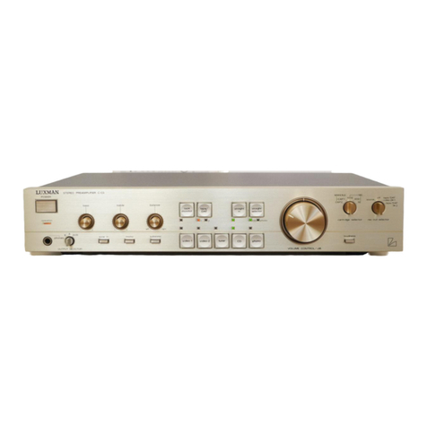
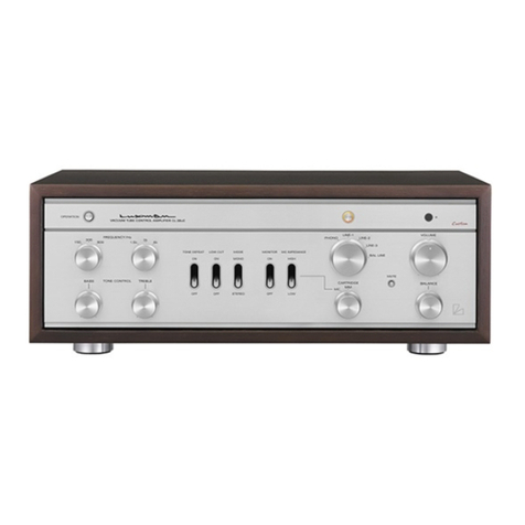
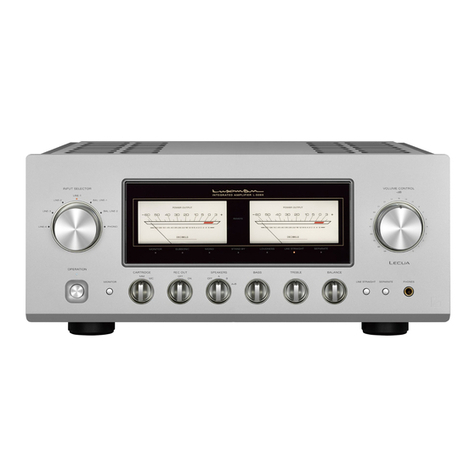
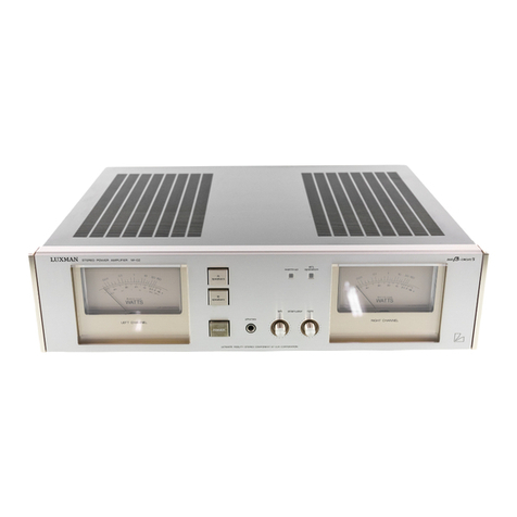
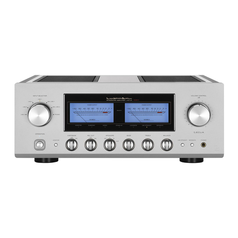
Luxman 308 User manual

My
ia
WUD
NOE
OPERATION
MANUAL
110W
STEREO
INTEGRATED
AMPLIFIER

TABLE
OF
CONTENTS
Outline
of
Control!
Functions
&
Connections
CRGAb
LA
ahn
SKE
ated
aa
tede
eo
kbh
nt
BOGS
OAR
ae
ous
ins
mae
oan
aa
teens
yi
SWC
OS
AC
ONIEIS:.
Sy
cert
ooh
cade
b
aettuse
a
mses
bin
Ca
OLY
hard
ESS
ARE
Sea
a
ot
Manin
noes
Wanietees
4
input
Se
Oulput
Terminals:
..isevhccaetati
aes
cee
eet
te
ee
UI
octal
a
lane
aunts
Seer
ce
genens:
6
COAMECT
ON
PIOC COUT
Oak
ak
orcas
nudes
ee
rob
ea
ao
caee
eae
acniale
ers.
o
tedden
td
eedot
aah
atPnetacecdewteaca
tania
sae.
8
RECOM:
Paver
fis
cawissha
wane
dn
shu
aa
Senda
memkuceame
ens
widens
see
aoe
dw
nents
Seip
e
ee
wanioman
dewey
cee
10
TABC
OGCK?
cixed
ae
ecnd
wwls
cenqarten
st
Ouse
betes
eee
en
et
Goa
che
topes
arabe
ideabelivaes
siete
rot
eats:
12
Tuner,
Operation
of
Controls
4-Channel
System
Standard
Curves

Thank
you
for
purchasing
one
of
our
quality
products,
the
LUXMAN
L~-308.
With
natural
care,
it
will
give
you
many
years
of
outstanding
performance
and
personal
delight.
Please
read
this
Owner’s
Manual
carefully
before
operating
the
unit.
The
first
section
diagrams
the
various
controls,
connections
and
summarizes
their
operation;
Keep
it
handy
for
quick
and
convenient
reference.
The
second
section
gives
detailed
descriptions
and
operating
procedures
for
the
electronic
and
mechanical
components
of
the
L-308.
Again,
thank
you
for
your
selection,
and
may
‘good
listening’
be
your
daily-pleasure.

Oufline
of
Control
Functions
-@
Speaker
Selector
@
Pilot
Lamp
Choice
of
Main
or
Remote
{or
both)
and
Off.
.
@®
Input
Selector
Switch
©
Bass
Programme
source
(Phono,
Tuner,
Aux,
etc.).
Inner
axts
for
Left
and
outer
axis
for
Right
shanaele
3
io
3
Turn
clockwise
for
bass
boost.
@®
Attenuator
=
Keep
fully
clockwise
for
normal
use.
Turning
counter-
@
Treble
clockwise
reduces
the
volume
up
to
18
dB.
Can
be
Inner
axis
for
Left
and
outer
axis
for
Right
channels.
used
as
a
volume
level
control
when
the
amplifier
Turn
clockwise
for
treble
boost.
section
is
used
separately.
©
Linear
Equalizer
@
Volume
The
“up
tilt
cuts
bass
and
boosts
treble.
““down-tilt”
cuts
treble
and
boosts
bass.
(A
full
description
@
Balance
appears
on
Page
16).
Both
channels
are
balanced
at
the
mid-position.
‘
Q)
Low
Cut
@®
High
Cut
OFF
at
NORMAL.
ON
at
either
20
Hz
or
70
Hz.
Useful
for
rumble
filtering,
etc.
'
PEPER
CETTE
CARE
os
SOLID
STATE
STERHO
INTEGRATED
=a
Fasc
Wart
-
pin
UNIAR
ERHIALHZER
amain
&
ceoente
IREBtE
up
Hft.
nai
phono
.
down!
|
hed
*
aes
:
eT
remote.
OFF
at
NORMAL.
ON
at
either
7
KHz
or
12
KHz.
Useful
for
scratch
filtering,
etc.
low
cut
digglbeut
manitor
dudlsiny
Inw
bnost
Jus
*KH:
deck
I
ftoy
VOLUME
-@-
BALANCE
stereo
monat+®.
.-
So
SO
Pevorse
¢
ix
1Sf)
re
60
1
aK
o
4
:
=
normal
—~———--
FY
—
TY
r.
)
—
®
=
\OunCe
.
°
Em
frequent
y/H7
tone
He-festt
dun?
1Km,
declt-24rh
?
Fol
deck
J
otlenuate
@®
Power
Switch
®
Monitor
Deck-1
or
Deck-2/4ch
for
tape
playback.
For
Phono,
©
Phono
Tuner,
Aux,
etc.,
set
at
SOURCE.
@®
Dubbing
From
Tape-1
to
Tape-2,
move
to
the
upper
position.
From
Tape-2
to
Tape-1,
move
to
the
lower
position.
Otherwise,
leave
at
SOURCE.
@
Mode
Selector
Switch
7)
Treble
Frequency
Selector
Stereo,
Monaural
selection,
etc.
.
Choice
of
turnover
point
from
three
frequencies.
@
Deck-1
Reproduction
Jack
Used
in
conjunction
with
the
Monitor
Switch
for
playback
from
a
tape-recorder.
For
connection
of
stereo
headphones.
@
Bass
Frequency
Selector
Choice
of
turnover
point
from
three
frequencies.
©
Tone
Controls
Switch
When
at
NORMAL,
it
allows
full
tone
control.
When
@
Deck-1
Recording
Jack
at
LOW
BOOST,
it
gives
an
extra
bass
boost,
and
Used
in
conjunction
with
the
Monitor
Switch
for
when
at
DEFEAT,
it
provides
a
flat
response.
recording.

¥
Connections
@
GND
Terminal
For
grounding.the
amplifter.
@
Phono-1
2.2mV
sensitivity.
For
connecting
the
first
turntable.
@
Phono-2
2.2
mV
sensitivity.
For
connecting
the
second
turntable.
¢)
Tuner
Input
For
connection
of
AM/FM/LW/SW
tuner.
&)
Aux-1
Use
for
a
second
tuner
or
qther
audio
equipment.
@
Aux-2
Use
for
a
second
tape
player
or
other
equipment.
3
8
::
308
en
TRE
meno,
nee
am
—-
ee
%-0-
‘on
on
Gh
‘O
O-
ox
~¢
Deck-1
Connector
(DIN
type)
For
recording
and
playback.
-@
Rec.
Out
(Deck-1)
Connect
to
the
input
of
tape-recorder
1.
‘€
Monitor
(Deck-1)
Connect
to
the
output
of
tape-recorder
1.
@
Rec.
Out
(Deck-2)
Connect
to
the
input
of
tape-recorder
2,
or
connect
to
a
4-channel
system.
@
Monitor
(Deck-2)
Connect
to
the
output
of
tape-recorder
2.
€
Pre-Out
For
independent
use
of
the
pre-amplifier
or
for
a
multi-amplifier
system
with
a
channel
divider.
——(
Tuner-Level
-—)
Main
Speakers
Red
terminals
are
positive
(+):
black
terminals
are
negative(—).
€
Remote
Speakers
,
Red
terminals
are
positive
(:+);
black
terminals
are
negative
(—).
@
AC
Outlets
(Unswitched)
Two
extra
outlets
for
AC
current.
Power
is
always
available.
&
AC
Outlet
(Switched)
Power
for
this
extra
outlet
depends
on
the
Mains
Switch.
(Ee
OEE
ee
EA
PEE
AEE
oh
;
A
Use
to
adjust
possible
volume
level
deviations
from
various
programme
sources.
9
Input
Impedance
for
Phono-1
Check
the
specification
for
each
type
of
cartridge
and
set
this
control
accordingly.
—_
Main
In
For
independent
use
of
the
main
amplifier
section.
€
DC
Speaker
Fuses
@
AC
Line
Fuse
@
Mains
Power
Input

Switches
&
Controls
@
Speaker
Selector
Switch
(SPEAKERS)
This
amplifier
offers
convenient
use
of
2
speaker
systems,
Main
and
Remote.
You
can
choose
independent
or
simultaneous
driv-
ing
of
1
or
2
systems
as
per
the
indication
on
the
front
panel.
When
both
Main
and
Remote
speakers
are
used,
make
sure
that
the
overall
impedance
is
not
less
than
4a.
At
the
OFF
position,
the
speakers
are
disconnected
from
the
amplifier,
and
you
can
enjoy
private
listening
by
headphone.
@
Mains
Switch
(POWER)
Press
alternately
for
ON
or
OFF.
@©
Headphone
Jack
(PHONES)
Connection
of
a
stereophonic
headphone
to
this
jack
allows
pri-
vate
listening.
Output
signal
is
always
available
regardless
of
the
position
of
the
Speaker
Selector
Switch
(1).
For
private
listen-
ing,
however,
set
the
Speaker
Selector
Switch
at
the
OFF
posi-
tion.
@
Bass
Level
Control
(BASS)
A
clockwise
turn
of
the
control]
boosts
the
bass
response,
and
a
counter-clockwise
turn
decreases
and
cuts
the
bass.
This
control
has
a
click-stopper
with
11
points.
It
yields
a
flat
frequency
res-
ponse
when
set
at
the
centre
of
the
rotation
angle.
You
can
choose
a
turnover
(roll-off)
frequency
of
150Hz,
300Hz
or
600Hz
with
the
Selector
Switch
(5).
The
Bass
Level
Contro!}
is
of
dual
concentric
construction
and
permits
separate
control
of
either
the
right
or
left
channels:
the
outer
axis
is
for
the
right
channel,
and
the
inner
axis
is
for
the
left
channel.
This
contro!
usually
controls
both
channels
simultaneously,
but
you
may
adjust
either
channel
by
holding
one
axis
while
turning
the
other.
The
click-stoppers
are
only
for
the
outer
axis,
i.e.,
the
right
channel.
@
Bass
Frequency
Selector
Switch
Bass
turn-over
(roll-off)
frequencies
can
be
selected
with
this
switch.
When
the
desired
frequency
(150Hz,
300Hz
or
600Hz)
is
set
by
this
switch,
tone
contro]
starts
to
function
at
the
selected
frequency.
At
the
DEFEAT
position,
a
flat
frequency
response
is
obtained,
regardless
of
the
position
of
the
Bass
Level
Control
(4).
PR
Ne
NN
ioe
Papers
“.
geet
ene
te
see
=
ais
wes!
+
hoot
"
wet
L
\
Yrs
7a
ter
oue
gt
cee
1
:
nod
“i
fs
tar
6
hee
vs
sort
Neamt
‘
“
bane
@
Treble
Level
Control
(TREBLE)
A
clockwise
turn
of
this
knob
boosts
the
treble
response,
while
a
counter-clockwise
turn
decreases
the
treble.
This
contro!
is
of
the
same
construction
as
that
of
the
Bass
Level
Control,
and
its
operation
corresponds
to
that
described
in
(4).
@
Treble
Frequency
Selector
Switch
Function
wise,
it
is
the
same
as
the
Bass
Frequency
Switch
described
in
(5).
@
Linear
Equalizer
(LINEAR
EQUALIZER)
This
is
a
new
tone
control
which
provides
a
tonal
compensation
specifically
intended
for
subtly
augmenting
regular
tone
controls.
With
the
control
in
its
mid-position,
flat
frequency
response
is
achieved.
When
switched
to
either
of
2
“up
tilt’
positions,
the
entire
response
curve
is
rotated
so
as
to
linearly
increase
treble
response
while
simultaneously
decreasing
bass
response.
Con-
versely,
selection
of
a
‘‘down
tilt”
position
rotates
the
response
curve
In
a
clockwise
direction
and
provides
a
gradual
decrease
of
treble
and
a
simultaneous
increase
of
bass.
This
equalizer
is
not
released
even
when
the
Tone
Controls
Switch
(9)
is
set
at
the
“tone
defeat’
position.
For
further
details,
refer
to
the
Operation
of
Linear
Equalizer
(Page
16).
©
Tone
Controls
Switch
This
switch
releases
the
function
of
the
tone
controls
(4
5,
6,
7
above)
when
set
at
the
‘tone
defeat’
position.
To
operate
these
controls,
this
switch
must
be
set
at
the
centre
or
NORMAL
position.
It
functions
as
a
low
booster
at
the
“low
boost”
posi-
tion
where
bass
frequencies
below
70Hz
are
boosted
at
the
rate
of
6
dB/oct.
In
case
this
amplifier
is
used
as
a
component
ampli-
fier
of
a
4-channel
system,
take
care
with
the
phase
matching
of
the
speakers,
since
the
phase
of
signals
becomes
reversed
when
they
pass
through
the
tone
controls
(normal
or
low
boost),
while
remaining
norma!
at
the
‘‘tone
defeat”
position.
Refer
to
the
Operation
of
Low
Booster
and
Connection
of
4-CH
DE-
CODER
(Page
16).
@
Low
Cut
Filter
(LOW
CUT)
OFF
at
the
centre
position.
When
moved
up
to
the
7OHz
posi-
tion,
a
bass
roll-off
occurs
at
70Hz
at
the
rate
of
6
dB/oct.
When
moved
down
to
20Hz,
the
roll-off
occurs
at
20Hz.
For
further
details,
refer
to
Low
Cut
Filter
(Page
16).

®
High
Cut
Filter
(HIGH
CUT)
OFF
at
the
centre
position.
When
moved
up
to
the
7KHz
posi-
tion,
the
amount
of
high
frequencies
is
reduced
sharply
at
the
rate
of
6
dB/oct.
When
moved
down
to
the
12KHz
position,
the
roll-off
starts
at
12KHz
For
further
details,
refer
to
High
Cut
Filter
(Page
16).
@
Tape
Monitor
Switch
(MONITOR)
The
input
function
selector
(phono,
AUX,
etc.)
is
separated
from
the
volume
and
tone
contro]
section.
If
a
tape
recorder
is
not
connected,
and
this
switch
is
moved
from
NORMAL
to
either
of
the
tape
inputs,
no
sound
will
be
heard.
In
case
a
3-head
tape
recorder
is
used,
simultaneous
playback
monitoring
is
possible
while
recording.
In
this
case,
the
amplifier
receives
the
playback
signals
either
from
the
Tape
Monitor
terminals
(32,
34),
the
Tape
Connector
(23)
or
the
tape
reproduction
jack
(17),
while
at
the
same
time
feeding
the
recording
signals
to
the
Recording
Output
terminals
(31,
33),
the
Tape
Connector
(23),
or
DECK-
1
recording
jack
(18).
In
case
a
matrix
4-CH
decoder
is
connect-
ed
to
the
DECK-2
Monitor
(34)
and
Recording
Output
terminals
(33),
this
lever
switch
must
be
set
at
the
DECK-2/4ch
position.
Eor
further
details,
refer
to
Connection
of
4-CH
DECODER
(Page
17)-
@®
Tape
Dubbing
Switch
(DUBBING)
Tape
dubbing
(reprinting)
is
possible
with
this
switch.
When
the
leveris
set
at
the
“1
to
2”
position,
the
playback
sound
of
the
DECK-1
terminals
can
be
printed
on
DECK-2,
and
vice
versa
when
set
at
the
2
to
1°”
position.
While
in
the
dubbing
process,
it
is
possible
to
monitor
with
the
Tape
Monitor
Switch
(12).
Except
when
reprinting
a
tape,
it
is
recommended
that
this
switch
be
set
at
the
centre,
SOURCE
position.
@
Pilot
Lamp
This
lamp
indicates
that
the
Mains
Switch
(2)
and
the
electric
current
are
On.
:
®
Input
Selector
Switch
This
switch
permits
proper
selection
of
desired
programme
sources
(Phono-1,
Phono-2,
Tuner,
Aux-1,
Aux-2).
@
Mode
Selector
Switch
Use
this
switch
for
selecting
reproduction
modes
such
as
Stereophonic
or
Monaural.
For
further
details,
refer
to
Mode
Selection
(Page
14).
@
DECK-1
Reproduction
Jack
(IN)
This
jack
has
a
function
equivalent
to
that
of
the
Deck-1
Moni-
tor
terminals
(32)
on
the
rear
panel.
Plug
in
the
line
output
of
the
tape
recorder,
and
you
can
monitor
by
setting
the
Monitor
Switch
(12)
at
the
““deck-1"
position.
@
DECK-1
Recording
Jack
(OUT)
This
jack
hes
a
function
equivalent
to
that
of
the
Deck-1
Re-
cording
Output
terminals
(31).
Recording
output
is
always
a-
vailable
from
this
jack
in
so
far
as
an
input
is
given
to
the
amplifier.
If
the
Dubbing
Switch
(13)
is
set
at
the
‘2
to
1”
posi-
tion,
this
jack
will
be
connected
with
the
Deck-2
Monitor
termi-
nals,
and
recording
output
will
be
available
from
the
Deck-2
terminals
(33).
©
Attenuator
(ATTENUATE)
Adjustment
of
this
control
makes
it
possible
to
pre-set
efficiency
of
the
Volume
contro!
(20)
in
the
range
of
0
dB
to
—18
dB
(about
).
Also,
since
this
attenuator
is
placed
at
the
entrance
of
the
main
amplifier
section,
it
can
be
used
as
an
input
level
setter
for
independent
use
of
the
main
amplifier
section.
@
Volume
Control
(VOLUME)
A
clockwise
turn
of
this
control
increases
volume,
while
a
counter-clockwise
turn
decreases
and
finally
cuts
out
volume.
@
Balance
Control
(BALANCE)
The
volume
balance
on
right
and
left
channels
can
be
adjusted
with
this
control.
Turn
it
clockwise,
and
the
volume
of
the
left
channel
will
decrease;
counter-clockwise
causes
a
dectease
of
the
right
channel.
When
the
volume
of
both
channels
is
balanced,
monaural
reproduction
sound
comes
from
the
centre
of
both
right
and
left
speakers.
This
point
is
usually
obtained
by
setting
the
click-stopper
at
its
centre
point.

Inout
&
Outpu
Terminals
&)
Earth
Terminal
(GND)
Connect
the
earth
lead
wire
of
the
record
player
(from
motor
or
pickup
arm)
to
ground
the
amplifier.
€
Tape
Connector
(CONNECTOR)
This
connector
is
of
DIN
standard.
With
the
recording
output
terminal
(REC OUT)
and
the
tape
monitor
terminal
in
it,
con-
nection
for
recording
and
playback
is
feasible
with
a
single
lead-
wire with
DIN
plug—
providing
the
tape
recorder
has
the
same
connector.
For
playback
through
this
connector,
the
Monitor
Switch
(12)
must
be
at
the
“deck-1"
position,
and
the
Dubbing
Switch
(13)
at
the
SOURCE
position.
Recording
output
signal
is
always
available
from
this
connector,
except
when
the
dubbing
switch
is
set
at
the
‘’2
to
1”
position.
@
PHONO-1
Terminal
For
playback
through
magnetic
cartridge
(MM,
MI,
MC
type).
Input
sensitivity,
2.2mV.
Input
impedance
is
selectable:
50Kaq,
65Ka,.
and
90Ka.
Except
for
very
low
output
MC
type
cartridge
(output
voltage,
0.01mMV-0.1mV).
almost
all
cartridges
can
be
used.
For
such
MC
type
cartridges
of
very
low
output
level,
it
is
necessary
to
boost
voltage
up
to
the
specified
level
by
use
of
step-up
transformers
or
a
head-amoplitier.
&
Input
Impedance
Selector
for
PHONO-1
This
selector
permits
selection
of
desired
impedance:
50Kaq,
65Kao,
and
90Ka.
With
MM
type
cartridge,
frequency
response
varies
according
to
load
impedance.
For
the
cartridges
which
tend
to
intensify
the
high
frequency
range,
set
the
load
impedance
at
the
50Ka
position.
On
the
contrary,
for
those
which
tend
to
attentuate,
setting
at
9OKQ
is
recommended.
Because
the
car-
tridge
of
65Ka
is
presently
dominant
in
the
market,
this
ampli-
fier’s
selector
is
set
at
65Ka.
€&
PHONO-2
Terminal
Same
as
PHONO-1
Terminal,
except
that
the
input
impedance
is
fixed
at
65Ka.
&
TUNER
terminal
For
reproduction
of
tuner
(AM/FM/LW/SW).
The
input
level
can
be
adjusted
by
the
Level
Control
for
TUNER
terminal
(28).
Max.
sensitivity,
100mvV.
»-
O-
O-
gs
ao)
pt
j
i
<a
sam
ia
Py
Wo
¢
SOE
=
E
yc
©
}
@
Level
Control
for
TUNER
Terminal
This
ts
a
variable
resistor
to
set
an
Input
level
of
the
TUNER
terminal.
It
can
be
used
to
adjust
possible
volume
level
devia-
tion
at
the
time
of
selection
of
the
Input
Selector
switch.
This
amplifier
is
delivered
with
volume
set
at
the
extreme
counter-
clockwise
position.
@®
@)
AUX-1,
2
Terminals
These
are
auxiliary
input
terminals
for
playback
of
flat
frequency
response
such
as
AM/FM
stereo-tuner,
line
output
of
a
tape
recorder,
or
the
audio
output
of
a
television
receiver.
Input
sen-
sitivity,
T100mV.
Input
level
is
not
controflable
in
conjunction
with
the
Leve!
Contro!
for
TUNER
(28).
@
DECK-1
REC.
OUT
Terminal
(Recording
Output
Terminal)
A
signal
for
recording
is
taken
out
from
this
terminal
(always
available
when
an
input
signal
is
given
to
any
of
the
input
termi-
nals).
In
case
the
Dubbing
Switch
(13)
is
set
at
the
“2
to
1”
position,
the
recording
signals
come
from
the
DECK-2
recording
output
terminal.
@
‘“DECK-1”
Monitor
Terminal
Playback
of
the
line
output
of
a
tape
recorder
is
possible
from
this
terminal.
It
is
put
into
operation
when
the
Monitor
Switch
(12)
is
set
at
the
‘“deck-1”
position.
In
case
a
3-head
tape
re-
corder
is
used,
simultaneous
playback
monitoring
is
possible.
&
“DECK-2”
REC.
OUT
Terminal
(Recording
Output
Terminal)
Offers
the
same
function
as
the
DECK-1
REC.
OUT
terminal
(31).
lf
the
Dubbing
Switch
is
set
at
the
1
to
2”
position,
the
signal
from
the
DECK-1
terminal
is
available.
If
the
Dubbing
Switch
is
at
the
SOURCE
position,
the
recording
signals
are
fed
to
both
DECK-1
and
DECK-2
terminals
for
simultaneous
recording
on
2
tape
recorders.
In
case
a
matrix
4-CH
decoder
is
used,
this
terminal
has
to
be
connected
with
the
input
terminal
of
the
decoder
with
a
pin
jack
cord.

@
““DECK-2’’
Monitor
Terminal
Functions
the
same
as
the
DECK-1
terminal
(32).
Tape
playback
is
possible
if
the
Monitor
Switch
Is
set
at
the
DECK-2/4ch
posi-
tion.
In
case
this
amplifier
is
used
as
a
2-CH
amplifier
for
a
matrix
4-CH
system,
2
of
4
channels
at
the
output
side
of
the
decoder
should
be
connected
to
this
terminal,
and
the
Monitor
Switch
should
be
set
at
the
“deck-2/4ch”
position.
€
Pre
Amplifier
Section
Output
Terminal
(PRE
OUT)
The
whole
output
in
the
pre-amplifier
section,
including
the
tone
controls
and
the
linear
equalizer,
can
be
taken
out
from
this
terminal.
Output
voltage
is
60OmV
against
the
standard
input.
When
using
a
shield
wire,
there
is
no
attenuation
in
the
high
frequencies
because
this
terminal
has
sufficiently
low
output
impedance
of
about
100.
This
terminal
is
for
independent
use
of
the
pre-amplifier,
as
well
as
for
a
mulit-amplifier
system
using
a
channel
divider.
Usually,
this
terminal
and
the
Main-Amplifier
Input
Terminal
(36)
are
coupled
by
a
jumper
cord.
€
Main-Amplifier
Section
Input
Terminal
(MAIN
IN)
The
Main-Amplifier
section
can
function
independently
when
the
signal
is
passed
through
this
terminal.
The
input
sensitivity
is
6OOmvV.
The
variable
Attenuator
(19)
is
inserted
just
after
this
terminal,
permitting
adjustment
of
the
input
level
in
case
of
the
independent
use
of
the
main-amplifier
section.
&
€
Speaker
Terminals
(Main
and
Remote)
The
speaker
systems
should
be
connected
to
these
terminals.
Press
the
cap
of
the
terminal
and
insert
the
bare
speaker
cord
into
the
terminal
hole,
then
release
it.
Firm
connectionis
now
made,
These
terminals
are
coupled
with
the
speaker
switches,
and
the
speaker
switch
must
be
set
at
the
position
corresponding
to
the
terminal
to
which
the
speaker
systems
are
connected.
37
ts
for
the
main
speaker,
and
38
is
for
the
remote
speaker.
The
red
terminal
is
for
(+)
and
the
black
for
(—).
For
further
details,
refer
to
Connection
of
Speakers
(Page
9).
€
DC
Fuses
(RIGHT
and
LEFT
SPEAKER)
Short
circuit
of
the
speaker
terminals
or
extremely
low
impedance
given
by
the
speakers
may
cause
the
DC
fuses
to
blow
out.
In
such
a
case,
ascertain
the
cause
and
correct
it.
Replacement
of
the
fuses
is
done
by
turning
the
fuse
cap
in
the
direction
of
the
arrow
mark
and
inserting
new
fuse.
Be
sure
that
the
mains
cord
is
disconnected.
&
Mains
Fuse
A
5A
fuse
is
inserted
in
the
mains
power
circuit
of
this
amplifier.
If
the
fuse
blows
out,
replace
it,
ascertain
the
cause
and
correct
it.
Replace
the
fuse
by
turning
the
cap
in
the
direction
of
the
arrow
mark.
Be
sure
that
the
mains
power
cord
is
disconnected.
@
Extra
Mains
Outlets
Convenient
for
supplying
mains
power
to
other
equipment
such
2s
AM/FM
tuner
or
record
player.
The
terminals
(41
UNSWITCH-
ED)
are
independent
of
the
mains
switch
of
the
amplifier,
while
the
other
(42
SWITCHED)
is
coupled
with
the
mains
switch.
The
supply
of
the
mains
power
depends
on
the
mains
switch.
The
total
capacity
for
the
UNSWITCHED
(41)
terminals
is
200W.
The
rated
capacity
for
the
SWITCHED
(42)
terminal
is
1OOW.
€
Mains
Connector
One
end
of
the
attached
mains
cord
should
be
connected
to
this
point,
while
the
other
end
with
plug
should
be
connected
to
the
mains
power
supply.

ca
ae
oo
Cont
ce
oe
Siloti
ae
afond
obued
a
3.
.
ow
3
ae
eS
i
of
pes
Cc
a:
2
uO
ee
Se
Oe
eS
OQ.
oe
ee
os
=
5
8
fC
€
Ose
ow
"
oe
or
=
P
Cc
.
OQ.
O
set
2
fae)
©
‘S)
i
a
wm
ts
®
my
we
Ci
ii
smu
Gus
ae
fa
ae
ly
Sour
‘ase
enous
ae
ly
ere
0)
esas
pe
ee
ee
ba
feet
Oa
a
a
Se.
OOO
@
tf
wo
go
ro
A
ONO
mee
4
io
Ooms
eS
ao
OC
Seria
«2
Mag
aes
;
Che
ee
eg
Loe
oo
j
O55.
Wee?
ger
oy
ee
cv
SE
S
nv
£4
}
OTe
mM
Dp
ft
and
i€
mM
ir
a
Svat
CO
NA
ME
aS
REN
SNALSESHIIERTS
videos."
aR
RONAN,
a
oO
on
eg
eee
‘
>
Soe
ee
Oe
ho
oe
fos
me
VG
|
i
iV
Wwe
fy
VA
e
r
y
the
ron
ine
er
oat
on
eC
erence.
su
'
ED
eee
oo
ee
a
Qo
—
e
.
Z
GO
eet
a
and
see
2
a
i
ee
OD
iA
WO.
es
Q
boa
a
Se
eee
et
et
Oe
cou.
a
-—
g
Doh
eo
ES
CY
oo
7
pe:
eee
ae
i
O..
Oe
SO
eg
eee
H
-_
>
BO
Ae
Tg:
lS
a
eo
Ou
9
k
rd
eee
paciiee
weed
c
sad
|
i
ee
Oe
a
ONO
SE
ee
ate
4
it
Oe
“Sy
a
a
2)
See
OD
Cy
oe
ie
de
§.-3
je
ag
po)
am
fi
(-)
2
ea
oo
3
i
2
i
:
~
©
Rafe’
©
Rae,
rears
ees
|
sia
ae
~y
i:
é
:
7
:
Oo
LS
ood
pecan
wo
a
oO
i
Mee
oe
en,
5
pe
ee
Fess
bor
se
og
Eg
oe
iS
oO
OO
wo
ee
i
i
es
eee
|
wi
Sve
Gee
or
=
>
S
Ooo
Oe
||
i
Lae
Arie
a
One
aed
ee
Os
ee
Oa
i
Jobedel
aE
Ce
a
Sos
O
en
ven
i
/
Sl
ae
ED
On
4
=
Go
Oe
Se
®
5
I
/
Beak
Sor
Deg
Oy
©
Oe
Oe
Cy
ae
i
i
ees
os
c
Cc
Og
ae
ee
eee
Ry
:
ioe
i
6
Ste
Cc
Ow
Se
O
bo
;
eee
id
”
Soe
Sse
gee
|
ees
ee
=
o
G
cee
OS
rr
ry
i
Oss
se
Dae
conidia
ag
a
3
2
4
a
Cy
ie
Spl
ewe
deed
wee
on
ri
|
|
e
é
‘
:
FP
ee
mein
ee
ee
|
aes
tte
cates
sar
sem
tne
niin
is
sea!
cram
Genin
as
afin
Sa
abn
picts
ue ei
i
|
ee
po
i
pol
|
i
i
r
‘uewscay
cman"
eteein
ne
akong
Nia
etme
Rafaeli”
mca
a
a
a
a
ee
a
ee
Pree
3
ae
o
a
2
hog
i
i
Po
aa
:
;
;
a4
a
i
i
r
‘et
iam
°
incon
wesecin”
vem
eo
Ne
tah
“dR
init”
Cone
«mamta
SON
non
eee”
“tier
emis
Wabi
tiem
Meniede
“Seam” Soumii
wrapoukt
ume
|
eens
vowina
vast
.
coe
ae
G
7
i
5
YY}
i
ae
ea
J
Se
Oe
DE
ce
Lo)
i
j
|
go
Rome
etme
Smee
“secera
-
au
mn
eee
“er
“eum
antisites
image!
mae
Rha
wie
“WUE
oon
sear
mikocd
wenn
ican
sem
-
wince
cine
well
ON
O
po
erat
LOT
ae
Cc
t
i
{
a
pe.
cm
rol
Sree
a
ei
wo
te
ONS
Se
oe
G.S
©
it
acne
one
ee
@
>
arr
es
a
Oca
ars
om
mn
>
gros
oe
i
f)
SS
=
(De
(ap)
es
mis-con-
wees
OS
mp
es
Oe;
ub
rep
eee
Onl
rm
h
f
p
a
speaker
to.
th
fi
m
QoS
w
Oa
ab
eee
ee)
vee
are
ew
-
fo
CE
aaa
sed
tf)
a
pose
bea
co
Fe
oe
¢
MD
‘
ed
(@3)
wo
San
y
eave
On
|
uen
is
¥
s
:
I
j
Pp
“itl
-|
ql
n
|
t
(
&
req
LS
eee
ow.
f
{
|
g
ne
ae
b
tl
}
C
tched
for
some
reason
(e.
e
ma
the
ro
ae
-
ams
©
ee
Sago
©
no
ieee
ret
meal
:
Bs
=
ae
One
Boe
20)
;
.
en
eal
me
emmen,
C3
OS
&
O°.
O08
Oyo
a
Qo
on
in
pee
©)
qo
ee
:
ese)
se
ab
pe
See
ed
Eg)
oral
me
Cc
a
3.
mi!
f
f
Speakers:
a
T
Kers)
p
Stable
playback
cannot
be
(
nal
to
the
a
speaker.
|
spe
term!
=
wast
Tee
ee
OS
ion
oO
iC
Peeey
ie
nN
nN
Dp
a
Q
Nw
oO
GS
Oe
Goes
Q.
re
as
ie
cane
eer
Se
eee
a
2)
Sis
pees
O
fw
Og
@
Pit
<
QO
COR
£
{
|
|
a
|
:
|
EISEN
ROSTERS
ER
Ia
re
ease:
EEE
ES
SEI
RTE
aI
BREE
ARTEL
EE
n
if
=)
=
the
left
ctio
qy
OYE
Jes
et
pores
oe
eee
ohaet
:
ob)
a
(
tl
a
e
Connect
phase
is
\
Nn
(
t
mettre
ater
etneartaineewaraiancsact
eae
ionaaanchatennarteibeniireaer
ara
&
ar
MRR
uRRR
TENET
ey
ee
0D
|
qe
O
2
gp
}
OD
SS
:
Oe
es
@
Qse
9
Orie
SOP
Os
:
Dye
OO
=
TS
)
a
i
@
e
}
th
iped-
ces-
e
rtas
AUX
i
oe
th
e-
eS
d
for
)
fz
;
h
m
{1
unne
e
sho
ly
for
high
impedance
,
s
afd
2)
cc
Ss.
we
a
Or
GaSe
ON
gM
See
See
|
s
sho
e
he
aud
IO
e
to
be
su
iS-use
(REC
OUT
a
Tt
3
t
HO
eda
e
Oo
ee
*
epee
oe
pe
Sets
eee
$2
OO
G
ey
oe
—
=
OS
eg
>
oN
N
C
y
impedance
bi
id
output
in
u
i
put
t
i
€
a
C
Dp
O
ry
5
S
C
a
oO
ee
DE
ep
EO
ed
outo
able
gned
a
Qi
L
!
UJ
Ir
(a
Su
ite
ift
Ng
ut
|
ce
a
Ge
we
S
+
h
it
ox
ww
ee
0
S|
d
a
S$
A
so-
de
OO
Bi
a
a
Re
—
ape
>
©
aS
ap)
fae)
“cs
inpu
fa
h
19
S
y
lo
Lara
on
we
a}
6)
an
bent
rap)
ith
‘4
ee
oo
oy
cn
te
oe
a
nis
-
Cmca
=
te
3
Sg
eS
oaeem
OD
ae
Qe’
Ue
ee
oy
£
i
a
r
T
=
d,
especi
a
Yr
t
peda
es
CG
rss!
Oe
=
|
re)
One
od
gt
;
.
t
ry
UTD
eee
Lad
£
ee
|
/
ite
ee
a
esol
S
On
Ove
es
oe
og
=
SG
OB
Ge
Oe
Oe
Gai
ey
O ®
Lhe
SN
Tan
(
seri
ern
|
a
Seite
me
SZ
{I
V
ei
se
Y
C
compo
be
|
wees
2
Gs
eee
A
|
:
e
sak
O
r
is
[i
nec
cvemeterentnene-nceetnoneeneaerientnarestsinencemesiosinasitanicatainatinanniaintentn
f
/
eae
Sad
é
AT
|
WA
iat
Cc
SAVER
Ae
oe
eases
SAGE
}
t
le
y
e|
re
es
a
Cy
Ga
NS
ee
ean
Be
Ce
Pa
a
Ee
we
CT
Uy
oS
eee
SO
Re
Oe
O
~
Lesa
€
)
pea
araved
ASS
@
CZ
a
a
OOOO
ee
ey
Oey
a
5,
he
eee
Ps
oe
por
Qe
ee
Q:
a
™
ga
Cy
ee
OLS
ae
~
=A
ge
eR
ps
On
OL
On
ees
OOS
eB
O
a
ay
po
ee
ee
Me,
oa
O
bens
0)
Gone
on
s
“eon
2)
Bafeaion
OO.
iene
@
pet
OO
CO
pore
rok
east)
=
Ooo
palace
8
ors
42
|
ye
sk.
~
pee
cs
OO
oe
TAO
—~
Ayo
Oy
ORE
ae
CyesQ
tort
©
Oy
See
he
Pe
OO
eae
Bee
690
te
De
ere
De
icy
ae
‘mite
ra
aM
)
Qo
yg
gb
ee
ayes
a
So
eed
Mee
Re
eg
Qo
ee
a
Oa
Ae
SE
One
ee
es
ee
0
qt
Q
i
‘@)
al
te:
put
|
par
eque
tter
if
r
danc
Q).
an
t
|
mend
e
@)
S
u
ne
f
fr
ma
tput
and
mp
00
S
D
a
m
a
on
k
4
+
L
|
|
u
r
r
I
Cable
(Cord
Wi
a
u
{
h
U
S
NO
eee
prox
D
u
e
e
e
the
iPp
|
Q
ny
Mm
1d
O
TI
PON
5
vi
i
es
"
va
2A,
Pad
e)
e
10
herefore,
rec
A
Cc
era
It
d
moli
SINC
\
(a
i
i
on’
MS
ava
2
wt
t
vat
od
g
Ne
als,
ently
lov
ne
re
eas
te
ayy
c
Ie
seers
On
Dee
oes
O
ao
Nokes
«beep
coAteay
on
Weer
Oterner
Beaty
A)
wolves
aoa
Oe
SC)
So
oO
erm
yee
SOS
ae)
eet
cS
r
d
C
rOX.
T
onnect
Ss
p
nt
me
p
22
i
me
£
e)
=
Nat
|
:
rf
Fi
vilannsninninseneniinaninirasnaienicnramnatanAmenepiounrstnniiea
aint
wenatnnntsnein
onic
neti
eietmaesceisnetnmmmativaiel
|
ble
range.
the
pre-a
chee
abs
€
fk
NA
ee
CO
et
an
oe
Con
oe
POLES
ets
OQ
@
2
eS
G
ay)
S
:
C
Senders
rw
™
NO
ESO
OO
Oa
t
i
|
Bunsen
tices
HS
AAA
REEMA
Rb
NI
A
RISC
TR
OM
LO
NBER
EIEIO
MESES
NOES
NG
LORAIN
NEESER
ERENT
I
AAS
ORIN
TENET
EAT
NORE
7
ond
ce
pets
ayo
aa
ie)
rag
eR
ay
res
eS
OS
@
ue)
ee
eaten
Rt
EER
RIC
RES
MPSA
OE
ESI UEN
EEN
ESTE
LOE
SU
LOCDS
MOLISE
A
a
|
|
|
|
Hi
|
|
i
Hseeeneterite
ects
anneeonrtantetainonmsnitnai
Oo
EO
+o
Q
Sense
eee
Rew
ACS
mee
een
RE
|
Fae
eee
aes
io
@
:
©
fee
O
@
r:
A
OS
—
i
\
:
i
|
|
na
Q.
a
:
i
ake
A
®
=
te
i
on
a
wa
oO
=
:
a
re
eer
=
“
:
=
eye
ame
Sd
S
©
i
Ce
ee
ee
es
H
poke
a
@
ane
i
ae)
=
@
i
wo
—
a
ok
Ge
—
tee
gp
TR
ree
:
md
OQ.
Or
KO
coo.
S
ogy
a
REN
eee
Oo
mS
oon
OS
eS
2
C2.
k
of
Disc,
:
—
S
ee
ee
ee
a
yy
ae
sed
Ce
Oy
te
eg
ee
Do
Ong
Pe
re
Te
oy
Pe
Sere
=
oO
eae
ees
oped
Loa
©
O
;
ay
ge
QD
paces
-
Mee
we
Ls
p
io
el
a
oO
input
Terminals:
laybac
a
ed
oD
son-R.
a
eRe
RS
A
A
AE
TS
ESI
spend
C3.-
wo
.
Co
a
z
afd
if
ETRE
rm
ey
a
mourners
rideeniemeennes
pa
Lo
Sete
oo
SE
SEL
Un
Senne
om
5
(oo
a
ee
ae
ee
fede
te
a
|
on
fonts
fe
=
€2O
oe
Co
c
Co
ee
13
pee
=
=
Sena
al
~~,
oy}
Oo
eos
oe)
C
a0)
Basic
Connection
p
|
Connection
to
Bese

Record
Player
Connections:
The
player
has
2
cords
with
pin
plugs
at
their
ends
for
both
right
and
left
channels.
Connect
the
pin
plugs
to
the
input
terminals
of
this
amplifier
(PHONO-1
(24),
PHONO-2
(26).
The
player's
earth
lead
can
be
connected
to
the
GND
terminal
(22).
The
player's
power
flex
can
be
connected
to
the
extra
power
outlet
(41)
of
the
amplifier.
This
amplifier
is
provided
with
2
input
terminals
(PHONO-1
&
PHONO-2)
to
be
selected
by
the
input
selector
switch.
This
Is
useful
for
comparison
or
using
two
record
players.
For
use
of
one
player,
either
of
the
two
input
terminals
can
be
selected.
But
in
case
MM-type
cartridge
(Moving
Magnet)
is
used,
it
is
advisa-
ble
to
use
PHONO-1,
since
its
impedance
can
be
varied
(using
the
impedance
selector
at
the
bottom)
to
give
a
proper
load
to
the
cartridge.
Bax
fo}:
BY
LUX
COMP
JAPAN
pPHONO)
SERIAL
NO.
TO
L
7
RECORD
Lo
|
PLAYER
R
;
IMPEDANCE
DECK-1
Signal
Paths:
Put
the
disc
on
the
turn-table,
switch
on
the
phono
motor,
and
set
the
stylus
on
the
groove
of
the
disc.
Then
recorded
signals
begin
to
be
fed
to
the
amplifier.
First,
the
signals
fed
to
the
amplifier
through
PHONO
terminals
are
brought
to
the
equalizer
section,
where
recorded
signals
are
restored
to
the
original
fre-
quency
curve.
Incidentally,
this
equalizer
curve
has
been
standardized
to,
the
RIAA
curve.
The
equalized
signals
are
then
fed
to
the
input
selector
switch
(function
switch).
If
this
switch
is
not
set
at
PHONO
position,
the
signals
are
blocked
here
and
no
amplification
is
possible.
After
equalization,
the
signals
are
divided
into
two
channels
at
sufficiently
low
impeaance
(about
1002
to
prevent
possible
high
frequency
attenuation
caused
by
long
cables
or
floating
-—10—
capacitance)
by
the
emitter-follower
stage
annexed
at
the
last
portion
of
the
equalizer
section.
From
here,
one
line
goes
to
the
REC
OUT
terminal,
and
the
other
to
the
tape
monitor
switch.
If
the
Monitor
Switch
(12)
is
set
at
the
“SOURCE”
position,
the
signals
are
sent
to
the
mode
‘selector
switch,
balance
and
volume
controls,
but
if
at
the
‘“-DECK-1"
or
“DECK-2”
po-
sition,
the
signals
are
stopped
at
the
tape
monitor
terminals.
Except
during
tape
playback,
the
monitor
switch
must
be
kept
at
the
“SOURCE”
position.
But
when
the
input
signals
are
fed
to
PHONO
or
AUX
terminals,
recording
output
is
always
obtainable
regardless
of
the
position
of
the
monitor
switch.
Then
the
signals
are
sent
to
the
volume
contro!
through
the
mode
selector
and
balance
control.
Such
controls
as
Linear
Equalizer,
Low-cut
filter,
High-cut
filter,
Attenuator,
Low
booster,
and
Tone
controls
are
for
flexi-
ble
and
diversified
adjustment
of
playback
sound
and
do
not
block
the
signals
completely.
PREOUT
MAIN
IN
As
long
as
the
pre-main
Jumper
connector
is
hooked,
the
signals
reach
the
speaker
circuits
amplified
by
the
main
ampli-
fier.
Sound
reproduction
from
speaker
systems
is
thus
realized
if
the
Speaker
Selector
switch
is
set
at
the
position
correspond-
ing
to
the
speaker
terminals
to
which
the
speakers
are
connected.
Playback
Put
a
disc
on
the
turn-table
for
playback.
As
the
volume
control
is
turned
clockwise,
playback
sound
comes
from
the
speakers.
As
explained
above,
playback
is
possible
regardless
of
the
position
of
the
Mode
Selector,
etc..
Input
Selector
Switch
(15),
Monitor
Switch
(12),
Pre-Main
Amplifier
Connection
Jumper,
Speaker
Switch
(1)
and
Volume
Control!
(20)
should
be
set
at
the
correct
positions.
After
all
preparations
are
com-
pleted,
check
if
the
volume
levels
on
both
right
and
left
speakers
are
identical.
If
different,
adjust
them
with
the
Balance
Control.
For
Stereophonic
playback,
set
the
Mode
Selector
Switch
to
the
STEREO
position.

CARTRIDGES
Types
There
are
various
types
of
cartridges:
magnetic
type,
photo-
electric
type.
electrostatic
type
and
piezo-electric
type.
Most
predominate
is
the
magnetic
type
which
includes
the
MM
(Mov-
ing
Magnet),
the
IM
(Induced
Magnet).
the
MI
(Moving
Iron)
and
the
MC
(Moving
Coil).
The
PHONO
terminals
of
this
ampli-
fier
are
designed
to
match
with
these
types
of
magnetic
car-
tridges,
but
a
cartridge
of
low
output
level
(output
voltage
0.01
to
0.1mV)
cannot
be
directly
connected.
(Refer
to
the
Step-up
Transformer
for
MC
Type
paragraph.)
lf
using
the
photo-electric
or
electrostatic
type
cartridge.
choose
appropriate
input
terminals
according
to
the
explanation
sheet
of
the
cartridge.
Among
the
piezo-electric
types,
there
are
crystal
types
and
ceramic
types.
Generally,
these
types
can
be
connected
to
the
AUX
terminals,
but
the
equalizer
characteristic
will
be
incorrect
(further
equalization
will
be
needed).
For
this
reason,
they
are
seldom
used
in
high
class
units.
Input
Impedance
The
PHONO-1
input
terminals
(24)
are
coupled
with
a
3-step
(50Ka,
65KaQ
and
90Ka)
impedance
selector
(25)
on
the
rear
panel.
Except
fora
special
low
impedance
type
cartridge,
almost
all
currently
marketed
cartridges
specify
recommended
load
impedance
of
30/1
OO
Ka.
tn
this
range,
the
cartridge
with
a
65Ka
load
impedance
is
by
far
predominate.
It
is
known
that
variation
of
the
load
impedance
value
affects
the
frequency
response
to
a
great
extent.
The
graph
shown
here
illustrates
this
point.
Notice
that
a
low
load
impedance
cuts
treble
output,
while
a
high
load
impedance
causes
a
peak
in
the
treble
range.
The
degree
of
such
effect
is
notthe
same
with
different
cartridges,
but
generally
a
cartridge
having
a
higher
output
impedance
tends
to
be
more
delicately
influenced.
It
is
therefore
necessary
that
selection
of
a
proper
input
impedance
is
made
with
this
control.
5d8
:
5dB
~
BOHz
100Hz
a
aan
aInaESsnIn
ann
|
|
Step-up
Transformer
Unit
for
MC
Type
Cartridges:
:
This
amplifier
does
not
have
connectors
for
exclusive
use
of
a
step-up
transformer.
However,
if
input
voltage
step-up
is
desir-
ed,
use
of
the
LUX
mode!
6521S
pin-plug
step-up
transformer
unit
is
recommended.
This
completely
new
step-up
transformer
is
extremely
compact
and
features
highly
efficient
performance.
Fitting
of
this
transformer
to
the
amplifier
is
accomplished
through
the
PHONO
terminals.
By
using
this
transformer,
low
output
level
phonograph
signals
from
a
MC
(Moving
Coil)
cartridge
can
be
boosted
by
30
times.
The
core
of
the
transformer
is
made
of
super-permalloy
material
to
ensure
superb
frequency
response.
Bisection
winding
coil
construction
and
complete
shielding
provision
for
the
core
perfectly
eliminate
induced
noise
from
external
sources.
Specifications
(6521S
trans
unit,
2
pes.
&a
pair)
Primary
end
impedance
Less
than
40
Secondary
end
impedance
More
than
30Ka
Step-up
ratio
138
Frequency
response
40
to
30,000Hz
Output
voltage
distortion
500mvV,
0.02%
Induced
noise
level
Less
than
—80dB/m
Weight
12
grams
tkKHz
7’
BH
SS*«*WT'
KHZ
Effect
of
the
Load
Impedance
on
the
frequency
response.

Playback
from
Tape
Monitor
Terminals:
Almost
all
tape-recorders
and
tape-decks
currently
marketed
include
an
audio
amplifier
in
their
circuitry,
and
some
tape-
players
are
made
exclusively
for
playback.
Connect
the
output
terminal
(LINE
OUT)
to
the
Tape
Monitor
terminals
(32)
&
(34).
Then
set
the
Monitor
Switch
at
the
cor-
responding
position
to
which
the
tape-recorder
is
connected.
If
two
tape-recorders
are
connected
to
the
terminals
(32)
and
(34),
selection
between
either
unit
is
possible
by
the
Tape
Moni-
tor
Switch
(12).
This
amplifier
can
be
divided
into
two
sections:
one
before
the
Recording
Output
terminals
(REC.
OUT)
and
the
other
after
the
Tape
Monitor
Switch.
A
3-head
tape-recorder
makes
it
feasible
to
make
recordings
with
the
former
section
and
simul-
taneously
make
playback
with
the
latter
section.
Note
that
a
normal
function
cannot
be
expected
if
2
or
3
sets
of
tape-recorders
for
playback
are
connected
to
the
terminals
of
TAPE-1,
Tape
Connector
(23)
and
the
Deck-1
playback
jack
(17)
at
the
same
time,
since
these
three
are
coupled
in
the
inside
circuit
and
affect
each
other.
Therefore,
if
the
Tape
Monitor
terminals
and
the
Tape
Connector
are
used,
the
tape-recorders
should
be
connected
to
the
terminals
of
TAPE-2
(with
the
Moni-
tor
Switch
at
the
Deck-2
position)
and
to
the
Tape
Connector.
OO
LALA
TAPE
DECK
t
TAPE
DECK
=
be
Playback
from
AUX
Terminals:
Playback
of
tape
is
possible
if
the
line
output
of
the
tape-
recorder
or
tape-deck
is
connected
to
the
AUX
terminals
of
this
amplifier
by
use
of
a
pin-jack
lead,
and
the
Input
Selector
Switch
is
set
at
the
position
corresponding
to
the
AUX
terminals.
All
operations
in
this
case
are
the
same
as
those
for
the
playback
from
tuner
(Page
14).
Note
that
when
tape
playback
is
made
through
the
AUX
terminals,
the
fine
input
or
AUX
input
terminals
of
the
tape-
should
be
kept
free.
If
connected
to
the
Recording
Output
terminals
(REC.
OUT)
of
the
amplifier,
there
will
be
possible
oscillation
by
feed-back
of
signals.
Playback
from
Tape
Connector:
This
is
a
DIN
connector
and
is
convenient
for
simple
connec-
tion
with
a
patch
cord
between
the
tape-recorder
and
recording/
playback
connectors
of
this
amplifier.
Playback
from
the
Tape
Connector
is
possible
if
the
Monitor
Switch
is
set
at
the
DECK-1
position.
(Make
certain
to
use
DIN
cord
only,
since
the
impedance
at
REC
OUT
terminals
is
kept
at
80KQ
+10KaQ.)
Playback
from
Tape
Jacks:
When
the
Tape
Playback
Jack
(17)
and
the
line
output
of
the
tape-recorder
are
connected
and
the
Monitor
Switch
(12)
Is
set
at
the
DECK-1
position,
playback
from
the
tape
jack
is
possible.
In
this
case,
it
is
necessary
to
modify
the
pin-jack
cord
to
the
plug-cord
as
shown
below.
OO
TAPE
DECK
OO
TAPE
DECK

Recording
on
Tape:
In
case
of
playback
of
various
programme
sources
through
input
terminals
of
this
amplifier,
the
same
signals
as
those
re-
produced
in
the
speakers
are
always
available
at
the
REC.
OUT
terminals
(31,
33)
and
the
Tape
Connector
(23).
By
connecting
these
terminals
to
the
input
terminals
(AUX
or
LINE
IN)
of
the
tape-recorder,
you
can
enjoy
simultaneous
recording
and
play-
back.
(It
is
recommended
that
the
Dubbing
Switch
be
kept
at
the
SOURCE
position.)
These
recording
signals
are
taken
out
beforé
the
tape
monitoring
stage,
and
there
is
no
influence
on
the
Filters,
Volume
or
Tone
Controls,
etc..
as
far
as
the
quality
of
the
recorded
signal
is
concerned.
Tape
Dubbing
(REPRINTING)
With
this
amplifier,
it
is
possible
to
reprint
from
one
tape-
recorder
to
another.
Connect
the
line
output
terminals
and
the
line
inout
(or
AUX)
terminals
of
one
tape-recorder
to
the
DECK-1
Monitor
and
REC
OUT
terminals
of
the
amplifier.
Like-
TO
TAPE
DECK
1
¢
dubbing
r
dubbing
ito2 ito?
102
e
ch
7101
ch
,2%01
a2
to
Dubbing
Source
Dubbing
1
onto
2
2
onto
1
wise.
connect
the
line
input
and
output
of
the
other
tape-re-
corder
to
the
DECK-2
terminals.
Dubbing
is
now
possible
by
use
of
the
Dubbing
Switch.
At
the
“1
to
2”
position,
the
tape
of
DECK-1
terminals
can
be
reprinted
on
the
tape
of
the
DECK-2
terminals,
and
vice
versa
at
the
‘2
to
1”
position.
In
this
way.
repetition
of
switching
between
SOURCE
and
“1
to
2"
or
2
to
1"
makes
possible
a
comparison
of
the
master
tape
and
the
re-
printed
tape.
Except
when
actually
dubbing,
it
is
recommended
that
the
Dubbing
Switch
be
set
at
the
SOURCE
position.
43
Simultaneous
Playback
Monitoring:
A
3-head
tape-recorder
ensures
simultaneous
playback
monitoring
and
recording.
In
this
case,
recording
on
tape
and
playback
of
the
recorded
sound
is
done
at
the
same
time,
and
connections
must
be
made
for
both
functions.
It
is
necessary
to
connect
the
REC
OUT
terminals
(31
or
33)
to
the
line
input
terminals
(AUX
Input)
of
the
tape-recorder,
and
the
Tape
Moni-
tor
terminals
(32
or
34)
to
the
output
terminals
(LINE
OUT)
of
the
tape-recorder.
The
Tape
Monitor
Switch
(12)
is
set
at
the
position
corresponding
to
the
terminals
to
which
the
tape-recorder
is
connected,
and
repetition
of
switching
between
SOURCE
and
DECK-1
or
DECK-2/4CH
allows
a
comparson
to
be
made
between
the
original
and
the
recorded
sound.
Possible
recording
errors
can
thus
be
prevented.
Incidentally,
note
that
reproduction
of
recorded
sound
becomes
a
little
delayed
as
compared
with
that
of
original
sound
since
there
is
a
gap
bet-
ween
the
recording
head
and
the
playback
head.
Simultaneous
playback
monitoring
can
be
made
through
the
Tape
Connector
(23)
as
well.
A
single
piece
of
DIN
cord
ensures
connection
for
recording
and
playback
on
the
Tape
Connector,
and
simple
operation
of
switching
between
SOURCE
and
DECK-1
ts
sufficient.
monitor
-
deck-1
deck-2/Ach
Simultaneous
Recording:
This
amplifier
is
provided
with
two
sets
of
REC
OUT
termi-
nals~enabling
simultaneous
recording
on
two
tape-recorders.
If
desired,
a
combination
of
recording
on
open-reel
recorders
and/or
cassette
recorders
can
be
accomplished.
Moreover,
if
the
Tape
Connector
and
Tape
Jack
are
used,
recording
on
four
tape-recorders
or
combinations
is
possible.
The
Dubbing
Switch
must
be
set
at
SOURCE
in
this
case.
This
facility
is
useful
for
safer
printing,
effective
recording,
etc..
As
the
impedance
at
the
REC
OUT
terminals
is
kept
sufficiently
low
(about
100),
mutual
interference
will
be
almost
nil
between
the
recorders
under
simultaneous
recording.
Playback
from
Other
Sources:
The
signals
of
flat
frequency
response
from
such
sources
as
TV
receivers
do
not
need
an
equalizer
stage.
For
playback
of
such
audio
equipment,
either
of
the
AUX
terminals
or
the
TUNER
terminal
can
be
used.
Connection
and
operation
is
the
same
as
that
of
a
tuner.

Playback
from
Tuner
Connect
the
tuner’s
Output
terminals
(left
and
right)
to
either
of
the
amplifiers
AUX
terminals
(29
or
30)
or
to
the
Tuner
terminals
(27).
The
Input
Selector
Switch
(15)
must
be
set
at
the
correspond-
ing
position.
As
shown
in
the
block
diagramme,
the
Input
signals
from
the
tuner
are
fed
directly
to
the
input
selector
circuit.
After-
wards,
the
signals
trace
the
same
blocks
as
are
explained
in
the
TAPE
DECK
section
and
are
reproduced
from
the
speaker
systems.
Both
for
FM
stereophonic
and
monaural
broadcasting,
the
Mode
Selector
Switch
should
be
set
at
the
STEREO
po-
sition,
for
such
accommodation
to
the
input
source
can
be
made
in
the
tuner.
Modulation
hum
in
the
AM
programme
can
be
eliminated
by
varying
the
distance
and
angle
of
these
components.
Input
Level
Control:
The
TUNER,
AUX-1
and
AUX-2
terminals
are
all
for
auxiliary
input
terminals
for
the
reproduction
of
flat
frequency
response.
For
the
TUNER
terminals
(27),
a
LEVEL
CONTROL
(28)
Is
pro-
vided.
The
input
sensitivity
is
100mV
when
the
control
is
at
the
extreme
clockwise
position.
Any
sensitivity
exceeding
100mV
can
be
obtained
by
turning
the
control
counter-clockwise.
If
other
programme
sources
are
connected
to
the
AUX
termi-
nals,
possible
deviation
of
the
input
level
among
the
various
sources
can
be
adjusted
by
the
LEVEL
CONTROL
if
the
pro-
gramme
source
with
the
highest
output
is
connected
to
the
TUNER
terminals.
tes
Operation
of
Controls
Mode
Selector:
This
amplifier
is
for
stereophonic
reproduction
and
incorpo-
rates
Independent
amplifiers
for
two
channels
(right
and
left).
Without
the
Mode
Selector,
the
signals
fed
to
the
right
channel
terminal
are
reproduced
at
the
right
channel
speaker
only.
The
Mode
Selector
is
placed
between
the
two
amplifiers
to
change
the
mode
of
reproduction.
Mode
Selector
Chart
connection
input
output
knob
position
performance
use
for
normal
stereo
playback
STEREO
NORMAL
normal
stereo
playback
when
program
STEREO
R
R
/reversed
stereo
,
Be
source
Is
revers-
REVERSE
L.
L
‘playback
|
ly
connected
right
input
signal
is
repro-
MONO
R
jaa
duced
from
both
right
and
lett
|
to+
monaural
speakers
left
input
signal
is
reproduced
from
both
right
and
left
speakers
program
source
playback
or
playback
of
monaural
record
with
a
stereo
phono
pick-up
right
and
left
input
signals
are
integrated
R R
MONO
L+R,
Volume
Control:
The
variable
resistor
of
this
control
yields
an
A
type
curve.
In
the
attenuation
characteristics
of
A
type,
the
turning
angle
ts
proportionate
to
the
attenuation
degree
(dB),
the
dB
value
and
the
volume
audible
to
human
ears. In
other
words,
the
rotation
of
the
control
is
in
proportion
to
the
sound
volume
felt
by
human
ears.
The
increasing
degree
of
volume
is
felt
quite
natural-
ly
as
the
control
is
turned
itn
the
clockwise
direction.
Attenuator
Switch:
This
switch
should
normally
be
kept
fully
clockwise
for
maxi-
mum
sensitivity.
When
turned
to
the
minimum
position,
the
volume
is
reduced
by
up
to
18dB
(about
%
power).
If,
however,
you
should
be
using
high
efficiency
loudspeakers,
such
as
horn-
loaded
types,
setting
the
switch
half
way
will
make
the
main
volume
control
easier
to
use.
Another
use
for
this
switch
is
as
follows;
If
you
wish
to
use
the
main
power
amplifiers
separately,
then
this
switch
will
adjust
their
input
sensitivities
to
match
your
other
equipment.

Balance
Control:
In
case
of
deviation
between
the
volume
Jevels
of
right
and
left
channels,
adjust
the
unbalanced
volume
level
with
this
contro!
(21).
A
complete
turn
of
the
control
to
either
the
clock-
wise
or
counter-clockwise
direction
causes
a
cut
off
of
the
volume
of
the
other
speaker.
The
volume
balance
of
both
chan-
nels
can
be
adjusted
so
that
monaural
disc
sound
reproduced
by
the
stereo
cartridge
comes
from
the
centre
of
the
right
and
left
channels.
At
mid
position,
the
volume
of
both
channels
is
adjust-
ed
to
the
same
level.
Thus,
a
proper
balance
is
established
through
all
playback
stages.
If
a
programme
source
is
un-
balanced
(or
the
speakers
are
placed
in
an
oblique
position),
establish
the
correct
balance
with
this
control.
BALANCER
VOLUME
CONTROL
LEFT
CH.
AF
AMP.
RIGHT
CH.
AF
AMP.
BALANCER
VOLUME
CONTROL
Tone
Controls:
The
ultimate
purpose
of
the
audio
system
is
to
make
high
fidelity
reproduction
of
programme
sources.
The
reproduction
and.
acoustic
conditions
do
not
always
match
with
recording
conditions,
and
it
is
impossible
to
reproduce
the
same
sound
as
the
original.
Also,
there
is
no
objective
standard
to
judge
a
good
sound
from
an
inferior
one.
The
only
possible
solution
is
for
every
listener
to
create
his
favorite
sound
according
to
his
own
taste.
It
is
therefore
very
important
that
the
audio
system
offers
a
facility
to
permit
flexible
controls
for
creation
of
the
best
sound.
This
amplifier
is
equipped
with
the
LUX
original
NF
type
turn-over
(roll-off)
frequency
selector
for
subtle
and
minute
control
of
the
reproduced
sound.
Tone
controls
include
Bass
Level
Control
(4),
Bass
Frequency
Selector
(5),
Treble
Level
Control
(6),
Treble
Frequency
Selector
(7)
and
Tone
Controls
Switch
(9).
lf
the
Tone
Controls
Switch
(9)
is
set
at
the
DEFEAT
position,
flat
frequency
response
Is
obtained
regardless
of
the
position
of
the
level
controls
and
frequency
selectors.
After
setting
the
Tone
Contro|
Switchs
(9)
at
the
NORMAL
position
and
controlling
the
levels
and
frequencies
as
desired,
you
can
again
obtain
flat
25s
frequency
response
by
resetting
the
Tone
Controls
Switch
at
the
DEFEAT
position:
controlled
tone
and
flat
tone
can
be
easily
recognized.
The
Bass
Frequency
Selector
(5)
has
three
positions:
150Hz,
300Hz
and
600Hz.
From
the
position
selected,
~~~"
Bass
Level
Control
(4)
begins
to
function.
In
‘
ee
other
words,
turn-over
(roll-off)
of
a
lower
frequency
range
below
the
frequency
which
has
been
selected
can
be
controlled
by
the
Bass
Level
Control
(4).
The
controllable
range
is
wider
by
150Hz,
300Hz
and
600Hz
respectively.
The
Bass
Level
Control,
which
functions
in
conjunction
with
the
Bass
Frequency
Selector,
is
a
tone
contro!
of
the
lower
range
of
the
fre-
ae
quency
response.
It
is
designed
so
that
response
©
=
re
is
flat
at
the
mid-position.
A
clockwise
turn
intensifies
the
low
frequency
range,
while
a
counter-clockwise
turn
yields
attenua-
tion.
For
easy
adjustment,
the
control
is
equipped
with
an
11-
point
click-stopper.
This
contro!
is
of
dual
concentric
construction,
and
usually
both
channels
are
controlled
simultaneously.
Separate
contro!
of
either
channel!
is
possible
if
oe
—
tess
one
axis
is
turned
while
the
other
is
held
by
hand.
The
inner
axis
is
for
the
left
channel
and
the
outer
axis
is
for
the
right
channel.
These
same
descriptions
are
applicable
to
the
Treble
Level
Control
(6)
and
the
Treble
Fre-
quency
Selector
(7).
The
Treble
Frequency
Selector
has
3
positions:
6KHz,
3KHz
and
1.5KHz
(controllable
range
is
wider
in
this
respective
Gs
order).
Treble
control
begins
to
function
ffOM
sencym:
2
the
position
that
is
selected.
This
control
also
~~
™™
=m
has
an
11-point
click-stopper,
and
a
clockwise
turn
boosts
the
high
frequency
range.
It
is
of
dual
concentric
construction
like
the
Bass
Level
Control.
For
details
of
these
tone
controls’
characteristics,
refer
to
the
attached
chart
concerning
the
response
curve.
Mode
Chart
LER
T
CHANNEL
CHANNEL
MODE
l.mono
L.
2.muoeno
R
3L+R
RIGHT
CHANNEL
RIGHT
CHANNEL

The
Linear
Equalizer:
Although
recordings
are
equalized
in
accordance
with
RIAA
standards,
it
is
quite
Common
to
encounter
variations
in
overall
tonal
balance
from
one
recording
to
the
next.
In
addition,
dif-
ferences
in
listening
environment
and
room
acoustics
often
require
subtle
degrees
of
tonal
compensation
that
conventional
tone
controls
cannot
correct
because
of
their
wide
range
and
overlapping
crossover
characteristics.
THE
LINEAR
EQUALIZER
control
provides
a
new
form
of
tonal
compen-
sation
specifically
intended
for
subtly
augmenting
regular
tonecontrols.
With
the
contro!
in
its
mid-position,
flat
frequency
response
is_
achieved.
Switched
to
either
of
the
two
“up-tilt”
positions,
the
entire
response
curve
is
rotated
about
a
1KHz
fixed
axis
so
as
to
linearly
increase
treble
response
while
simultaneously
decreasing
bass
response.
Con-
versely,
selection
of
one
of
the
“down-tilt”
positions
rotates
the
response
curve
in
a
clockwise
direction,
providing
a
gradual
decrease
of
treble
response
and
simultaneous
increase
of
bass
response.
Degree
of
slope
for
either
positive
or
negative
settings
has
been
carefully
preset,
and
the
overall
response
curve
maintains
complete
linearity
from
50Hz
to
above
10KHz,
unlike
the
curvature
in
response
normally
associated
with
ordinary
tone
controls.
Specifically,
when
the
contro!
is
turned
to
the
first
“up-tilt’
position,
it
will
decrease
bass
and
increase
treble
by
1.5dB
at
100Hz
and
10KHz
respectively,
while
selection
of
the
second
“up-tilt’”
position
will
result
in
a
3dB
cut
and
boost
at
these
same
frequencies.
Selection
of
the
first
“down-tilt”
position
will
de-
crease
treble
and
increase
bass
by
1.5dB
at
the
same
reference
frequencies,
while
the
second
“down-tilt”
position
provides
3dB
of
cut
(at
100Hz)
and
boost
(at
10KHz).
Combined
use
of
the
LINEAR
EQUALIZER
and
conventional
tone
controls
provides
a
degree
of
tonal
flexibility
which
cannot
be
achieved
with
any
other
tone
control
arrangement
presently
available.
Because
of
the
inherently
linear
nature
of
this
new
circuit,
it
introduces
no
increase
of
harmonic
distortion
at
any
of
its
settings.
LINEAR
EQUALIZER
Linear
Equalizer
“up-tilt”’
“down-tilt’”’
AG
Low
Cut
Filter:
When
this
filter
(10)
is
moved
up
from
the
centre
NORMAL
position,
the
low
frequencies
you
hear
are
cut
off
below
7OHz
at
the
rate
of
6dB/Octave.
When,
it
is
moved
down,
the
low
frequencies
are
cut
off
below
20Hz.
Thus,
it
is
useful
for
removing
low
frequency
noise
such
as
rumbling
of
the
phono
motor.
It
can
also
be
used
as
an
auxiliary
control
for
Bass
Level!
Control.
“,
loweut
hi
20Hz
High
Cut
Filter:
When
this
filter
(11)
is
moved
up
from
the
it
highcut
m
centre
NORMAL
position,
the
high
frequency
:
7KHz
dé
range
over
7KHz
is
cut
off
at
the
attenuation
rate
|
of
6dB/Octave.
When
moved
down,
the
high
frequencies
over
12KHz
are
cut
off.
Thus,
it
is
useful
for
removing
scratch
or
hissing
noise
and
can
also
be
used
as
an
auxiliary
control
for
Treble
Level
Control.
z
I2KHz
de
Operation
of
Low
Booster
The
Tone
Controls
Switch
(9)
has
two
func-
tions:
tone
defeater
and
low
booster.
When
this
switch
is
set
at
the
LOW
BOOST
position,
the
low
frequency
range
below
7OHz
is
boosted
with
a
slope
of
6dB/Octave
in
addition
to
other
tone
controls.
This
circuit,
effective
only
on
the
extreme
low
frequency
range,
allows
flexible
and
versatile
tone
adjustment.
For
instance,
probable
rise-up
in
a
small
room
of
approximately
10m2
in
the
neighbourhood
of
150
to
200Hz
can
be
subdued
with
this
control
by
lowering
the
bass
level
to
the
300Hz
position
on
the
Bass
Frequency
Selector.
This
process
can
sup-
press
such
unnecessary
rise-up
without
spoiling
the
response
at
the
extreme
low
frequency
range.
Moreover,
when
the
human
voice
sounds
unnaturally
stout,
it
can
be
adjusted
to
a
Clear,
natural
voice
by
switching
on
this
booster
and
cutting
the
low
frequency
range
a
small
extent
with
the
Bass
Level
Control.
low
boost
tone
defeat

4-Channel
System
At
present
there
are
many
4-channel
systems
available,
Of
these,
the
three
most
popular
systems
are
the
CD-4®
_
(com-
pletely
discrete
disc),
the
R.M.@®
(Regular
Matrix)
and
the
S.0.®
systems.
Even
though
the
LUXMAN
L-308
is
a
2-channel
ampli-
fier,
it
can
be
used
with
other
equipment
to
provide
4-channel
sound.
If
you
use
a
CD4@®
de-modulator
unit,
there
will
be
four
output
terminals.
Connect
two
of
these
(such
as
Left-Front
and
Right-Front)
to
the
AUX-1
input
terminals
of
the
amplifier.
For
details,
refer
to
the
De-modulator
Instruction
Manual.
Front-Left
RL
RR
Rear-Left
Demodulator
lf
you
use
either
the
R.M.®
or
S.O.®
system,
again
connect
two
of
the
four
outputs
to
the
AUX-1
inputs.
However,
most
of
the
available
de-modulators
do
not
have
built-in
Phono
amplifiers.
Therefore,
to
use
a
de-modulator
with
your
record-
player,
connect
the
inputs
of
the
de-modulator
to
the
Tape-1
outputs
of
the
amplifier
and
use
the
amplifier’s
Phono-1
inputs
for
the
turntable.
For
more
details,
consult
the
De-modulator
Instruction
Manual.
A
word
of
caution!
For
correct
phasing,
there
are
marks
on
the
back
panel:
@
over
the
Tuner,
Aux,
and
Monitor
inputs
and®
over
the
Main-In
terminals.
These marks
mean
that
the
speaker
output
is
in
phase
®
or
out
of
phase
®
with
the
inputs.
Front-Right
Rear-Right

T.H.D.
Vs.
POWER
PHONO
Input
Voltage
(Output:
REC.
OUT
Terminal)
“ °
Py
——
a
ee
ee
il
ee
ee
eee
ee
5OHz
100Hz.
Ssi(‘<i«é‘sé«S
Hz
KH
'BkH2
10kHz
0.05W
O.1W
0.2W
O.5W
1W
2w
5W
10W
=.
20W
5OW
(Input:
Main
in,
Load
89,
Both
channel
driven)
I.M.D.Vs.
POWER
Equalizer
(Output:
REC.
OUT
Terminal)
~BOHz
100Hz
iW
Frequency
.
(Input:
main
in
Frequency
&
Modulation
ratio
7OHz:
7kHz=
4:
1)
;
Ap

aig
POWER
BANDWIDTH
802
load
OdB:
30W
oss”
a
|
5OHz
100Hz
500Hz
1kHz 5kHz
10kHz
50kHz
DAMPING
FACTOR
82
ioad
1W
output
100
50.
DAMPING
FACTOR
50H2z
100Hz
5KOOHZ
1kHz
5kHz
tOkHz
5OkHz
LINEAR
EQUALIZER
epeisare
A-Up-tilt
2
B-Up-tlt
1,
C-Flal-
D-Down-tilt
1
‘E
-Downetilt
2)
1248
i
3,
BiB”
Pen
0dB
—
4dB
—8dB
20Hz
_
50Hz
~
100H2
|
200Hz
500H
z
kHz
|
2kHz
5kHz
10kKHz
20kHz
n24Q=
12dB
:
84B
4dB
OdB
:
—
4dB
'
—
8dB
—12d8
©
12dB
°-
8dB
:
4dB
:
ue
~
4dB
;
=
dB.
—12dB
|
12dB
8d8
4dB
odB
—
4dB
—
8d8
—12¢8
BASS TONE
CONTROL
Turn-over
(Rol-off}
Frequency;
150Hz
50Hz 100Hz
500HZ
1kH2z
5SkHz
tOkHz
BASS
TONE
CONTROL
Turn-over
(Roll-off}
Frequency;
300Hz
~
BOHz
100Hz
500Hz
1kHz
5kHz
1OkHz
BASS
TONE
CONTROL
Turn-over
(Roll-off)
Frequency:
600Hz
-BOH?
100Hz
500Hz
tkHz
5kHz
10kHz
50kHz
50kHz
5O0kHz
TREBLE
TONE
CONTROL
Turn-over
{Roll-off)
Frequency:
6kHz
ee
848
4dBi
5OHz
100Hz
500H2
1kHz
5kKHz
10kHz
5OkKHzZ
TREBLE
TONE
CONTROL
Turn-over
(Roll-off)
Frequency:
3kHz
8B.
.
4dB2
OdB:
err:
ae
--
8dB
—12dB°.
50Rz
100Hz
500Hz
ikHz
S5kHz
10kHz
5OkH2
TREBLE
TONE
CONTROL
Turn-over
{Roll-off)
Frequency;
1.5kHz
12dB
8dB
4dB
odB
408
--
8dB
—
12dB
.
BkHz
10kHz
5OHz
100Hz
00H
z
IkHz
=e
Table of contents
Other Luxman Amplifier manuals

Luxman
Luxman P-10 User manual

Luxman
Luxman L-430 User manual

Luxman
Luxman E-250 User manual

Luxman
Luxman 30 User manual

Luxman
Luxman EQ-500 User manual

Luxman
Luxman M-05 User manual

Luxman
Luxman CL 35 mk III User manual

Luxman
Luxman MQ-300 User manual

Luxman
Luxman L-590AXII User manual

Luxman
Luxman SQ507X User manual

Luxman
Luxman M-10X User manual

Luxman
Luxman L-507u User manual

Luxman
Luxman LX-380 User manual

Luxman
Luxman L-505u User manual

Luxman
Luxman L-505uX User manual

Luxman
Luxman SQ700X User manual

Luxman
Luxman L-507uX MARKII User manual

Luxman
Luxman L-400 User manual

Luxman
Luxman R-1070 User manual

Luxman
Luxman C-1000f User manual