manuals.online logo
Brands
  1. Home
  2. •
  3. Brands
  4. •
  5. Luxman
  6. •
  7. CD Player
  8. •
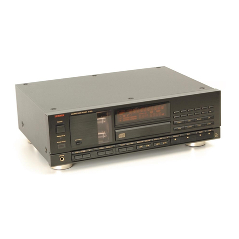
  9. Luxman DZ-112 User manual

Luxman DZ-112 User manual

SERVICE
L7
MANUAL
~
Compact
Disc
Player
DZ-112
DZ-112
Contents
Specifications
vcr
ce
ee
ee
ene
Een
een
Cree
ee
enter
Tene
ETE
EE
neat
ene
es
2
Controls
&
Switches-Front
Panel
coccrct
ster
teeter
nent
teen
tenet
e
nen
renee
ena
ene
e
tnt
e
nnn
es
3
to
5
Jacks
&
Terminals—Rear
Panel
core
creer
terete
renee
en
tee
eee
eee
eee
eee
EEE
TET
EEE
EERE
EEE
EEE
Ene
en ES
6
Controls
&
Switches—Remote
Controller
cccccr
cscs
teeter
eet
eter
eee
een
eee
eet
teen
eee
tenet
etre
enter
ne
nee
e
es
7
Disassembly
Instructions
ccresrte
street
eter
teeter
ete
teen
eet
e
nett
n
enter
cent
e
tare
e
nen
ne
ene
e
Enea
ne
es
8
Adjustment
Procedures
cirrrtre
steer
terete
etter
eee
tence
tener
eee
nen
nen eet
teen
tense
tere
ce
rere tent
e
eas
9
to
10
Adjustment
Locations
vrrrtcte
steers
entre
trent
ene
en
ene
eee
e
nner
ne
nen
teen
eee
n
ene
tet
caer
rete
eee
ee
teen
aes
11
=)
Cote}
ak
Yo
1-1
4
Cc
ce
12
Parts
Layout
on
P.
C.
Boards
and
Wiring
Diagram
creer
tree
rece
t
terete
eter
eter
renee
een
e
nce
en ee
ees
13
to
16
Schematic
Diagram
(1/2)
ccrececrer
etter
et
ete
teen
teen
een
eee
cence
ener
n
eee
e
eee
e
tenn
Eee
e
eee
ee
17
to
19
Schematic
Diagram
(2/2)
ctrsrcsssrere
reste
treet
ete
e
tener
eee
ene
tee
ener
ern
e
nee
e
nee
nen
teense
eens
20
to
22
Electrical
Parts
List
cecccc
cere
teeter
tet
ete
e
eter
een
arenas
Pte
tener
eee
nee
eet
teen
eee
e
nee
e
ene
e
ees
23
to
27
Cabinet
Assembly
Parts
List
corres
rrr
r
ttre
ttt
tert
n
entered
nner
n
te
eee
ee
nn
een
ene
renner
nena
eee
n
es
28
Exploded
View
(Cabinet)
cress
esc
terre
rete
eee eet
cnet
eee
ern
t
ent
eee
e
eee
ence
eee
e
een
e
een
e
ence
29
to
30
Exploded
View
(CD
Mechanism)
cerrrctrccr
terest
eee
treet
teen
n
cree
een
tener
e
ene
n
enter
eter
tana
n
sentence
31
to
32
CD
Mechanism
Assembly
Parts
|
5
33
Packing
Assembly
Parts
List
crrreet
ttre
ttre
treet
rte
etree
tee
tenn
een
n
tenn
eee
nett
eee
e
eee
e
ee
terete
n
eset
nee
e
tines
34
Packing
Method
View
vrrrrrester
street
teen
eect
eter
e
terete
entree
eee
eee
etree
ener
eee
Eee
ee
etn
E
eee
teen
eaten
Ts
34
Semi-conductor
Lead
Identifications
coer
tet
rte
eet
e
eee
eee
e
enn
eee
eee
ete
e
tence
net
en
tenes
35
to
40
Specifications
Sisters.
4
Pored
a
Wydwae
bande
pds
Seed
aes
Rey
eats
ben
orate
ge
Peewee
eeu
eres
Optical
(Compact
Disc
System)
Quantizing
Bit
Number
ccrceres
eee
eeee
eect
eee
e
eee
eee
ener
e
renee
eee
ene
e
ne
Ene
E
ES
16
Bit
Linear
System
Channele
sitie
semis
tin
aaosle
th
ecsigg
patadeiahie
MWe
tany
cnaahiedae
ni
Wale
S
ns
aeehieagh
eaves
tami
ee
eagens
2
Channels,
Stereo
Tel
|
oO
OOOO
OOOO
OOO
SOOOSOOOSOOSOOSCOOOCOSOSIOS
Semi-conductor
Laser
Pick-up
Output
Voltage
<-cercercceee
cee
eee
encesee
cere
eenenee
sere
geesenes
eres
ens
eneenee
ener
stenoses
cnet
anes
nen
eneeeeees
OV-+1dB
Frequency
Response
srrrtstrtterr
esc
ec
ese
te
teers
nce
ee
ee
neeer
nee
nent
erent
eet
eeeeeree
eens
ee en
ee
esc eca
ns
5~20kHz
+
1dB
T.H.D.C1KHz)
cece
terete
ce
seee
nee
e
eset
ene
e
nee
e
este
enn
ne
tenes
eee
eenennenengee
ene
enenecenenetenensenaeseaceee
1.008%
SAN
Ratio
cccecece
ete
eee
e
eee
n
ene
e
eee
nena
eect
eee
ENTE
EE
SEEDED
ED
REST
DISA
ADE
EEE
EERE
EE
ETE
SE
Eee
ER
EE
EEE
EL
99dB
Dynamic
Range
vrrcerccr
teeter
teeter
eee
eee
ee
ene
eee
ene
nner
EEE
EEE
E
EEE
EDEL
EEE
EEE
ERE
EEE
EEE
E
EEE
ES
91dB
Channel
Separation
(1KHz)
crttc
rc
terete
rte
tet
e
tenet
eee
e
eee
n
eee
ene
e
een
nen
n
renee
seen
eter enna
sn
eesee
sens
90dB
Headphone
Output
Voltage
(1kHz,
—10dB//8
OhM)
crrecss
etter
eee
e
eee
e
teen
eee
entre
eee
teeta
150mV
+
1dB
Power
Supply
crrrrrrrtersrrerreseees
AC120/220/240V,
50Hz
(General
European
and
West
German
Models
Only)
AC120V,
60Hz
(North
American
and
Canadian
Models
Only)
AC240V,
50Hz
(England
Mode
Only)
Power
Consumption
cccrtcree
scree
reer
eter
eee
eee
e
eee
eee
e
eee
eee
eee
EET
EEE
REALE
EERE
TEESE
EEE
EEE
EEE
EEE
-
15W
SOMEBONdUCtOrS.
treee
teres
Rata
Re
coma
ee
laa
Lote
eee
erage
EEaa
Aes
ae
tena
daemaaye’
21
IC’s,
24
Transistors,
2
FETs,
19
Diodes,
3
Zener
Diodes
Dimension
(WX
HX
DD)
certtet
etter
ene
e
nen
e
nee
nent
n
nee
n
nen
eee
teen
e
tenn
eee
t
ete
tees
438
x
85
x
311
Cmm)
Te
|
a
ea
4.5kg
NOTE:
Due
to
continuing
product
improvement,
specifications
and
designs
are
subject
to
change
without
no
tice.
CONTROLS
&
SWITCHES
—
FRONT
PANEL
DZ-112
1.
POWER
BUTTON
Press
this
button
to
turn
power
on
and
off
to
the
unit.
The
contents
of
the
programmed
play,
random
play
and
edit
play
are
kept
in
memory
even
if
the
power
is
turned
off.
When
one
of
the
programmed
play,
ran-
dom
play
and
edit
play
functions
has
been
set,
the
programmed
operation
will
start
when
the
power
is
turned
on.
When
no
programmed
operation
has
been
set,
normal
playback
will
start
from
the
first
track
on
the
disc.
2.
DISC
TRAY
Place
a
disc
on
this
tray,
label
side
up.
A
light
touch
“on
the
tray,
when
open,
will
cause
it
to
retrack
back
into
the
unit
ready
for
play.
Pressing
PLAY,
STOP,
PAUSE,
A-SCAN
or
any
of
the
DIRECT
ACCESS
but-
tons
will
also
close
the
tray
and
cause
the
unit
to
go
into
immediate
play
operation.
NOTE:
To
use
8
cm
(3
inch)
single
CD's,
place
them
on
the
inner
circular
grooved
area
marked
“8
cm
disc”
on
the
tray.
3..
VACUUM
FLUORESCENT
DISPLAY
Track,
index,
time
and
programming
functions
are
all
simultaneously
shown
in
this
display.
Refer
to
“opera-
tion
guidelines”
for
details.
4.
REPEAT
Button
In
normal
play
or
random
play
mode,
press
this
button
to
repeat
all
tracks
on
a
disc.
In
programmed
play
or
edited
play
mode,
pressing
this
button
will
repeat
only
those
programmed
or
edited.
Pressing
the
“repeat”
button
a
second
time,
will
can-
cel
the
repeat
function.
5.
A-PAUSE
(AUTO
PAUSE)
Button
Pressing
this
button
will
cause
the
machine
to
activa
te
PAUSE
automatically
at
the
end
of
any
currently
pla
y-
ing
track.
To
resume
play,
press
the
PLAY
buttor1.
While
the
auto
pause
function
is
activated,
A-PAUSE
will
show
in
the
display.
6.
STOP
(reset)
Button
(Ml)
One
press
of
this
button
will
stop
playback
and
retuusn
the
pick-up
to
the
beginning
of
the
disc.
A
secomd
push
will
clear
(reset)
all
memory
contents.
NOTE:
The
total
number
of
tracks
and
the
total
pla
y-
ing
time
on
the
disc
will
always
show
onthe
display
in
the
STOP
mode.
DZ-112
7.
PAUSE
Button
(
a
)
Press
this
button
to
temporarily
cease
playback
or
to
cue
up
a
track
or
segment
for
recording,
etc.
To
resume
playback,
press
the
“pause”
button
again
or
press
the
play
button.
NOTE:
Fast
Forward/Backward
scan
and
skip
oper-
ations
(items
#9
and
8)
are
still
operable
in
the
“pause”
mode.
8.
FAST
FORWARD/BACKWARD
SCAN
Buttons
(<<,
>>)
When
pressed,
these
buttons
provide
fast
forward
or
backward
scan
within
a
track
(music)
selection.
To
more
than
double
these
scan
speeds,
press
the
“pause”
button
(item
#7)
first.
9.
FORWARD/BACKWARD
SKIP
Buttons
(<
,
>>)
These
buttons
allow
one
to
“skip”
forward
or
back-
ward
over
any
track
in
one
track
increments.
Pressing
backward
(<)
once
will
cause
return
to
the
beginning
of
the
current
track;
a
second
immediate
push
will
cause
a
skip
back
to
the
preceding
track.
When
the
pick-up
comes
to
the
first
selection,
the
next
push
will
cause
it
to
go
to
the
beginning
of
the
last
selection
on
the
disc.
Pressing
forward
(»»)
will
cause
the
player
to
skip
forward,
one
track
at
a
time
for
each
successive
push.
When
the
last
selection
is
reached,
the
next
push
will
return
the
pick-up
to
the
first
track.
10.
PLAY
Button
{
>
}
Press
PLAY
button
when
loading
a
disc
for
immediate
playback
beginning
at
track
1
and
for
starting
a
pro-
grammed
sequence.
11,
A-SCAN
(AUTO
SCAN)
Button
Press
this
button
to
successively
play
a
beginning
of
each
track
for
ten
seconds.
During
the
auto
scanning
mode,
the
A-SCAN
indicator
will
appear
on
the
dis-
play.
12.
RANDOM
Button
Press
this
button
to
automatically
play
tracks
at
ran-
dom.
During
the
random
play,
the
RANDOM
indicator
will
appear
on
the
display.
CONTROLS
&
SWITCHES
—
FRONT
PANEL
13.
PHONES
Jack
Use
the
“phones”
jack
to
connect
stereo
headphones
for
private
listening.
14.
VOLUME
UP/DOWN
Buttons
Controls
volume
level
of
connected
stereo
head-
phones
and
the
VARIABLE
ANALOG
OUTput
jacks
on
the
rear
panel.
When
activated,
the
output
level,
as
measured
in
db
below
maximum
output,
is
shown
in
the
display.
15.
FADE-OUT
Button
Use
this
button
to
gradually
decrease
the
output
level
of
the
VARIABLE
ANALOG
OUTput
jacks
on
the
rear
panel
and
the
phones
jack.
When
the
fade-out
com-
pletes,
the
unit
enters
the
pause
mode
and
the
output
level
automatically
returns
to
the
original
level.
16.
T-FADE
OUT
(Time
Fade
Out)
Button
Use
this
button
to
gradually
decrease
the
output
level
of
the
VARIABLE
ANALOG
OUTput
jacks
on
the
rear
panel
and
the
phones
jack
after
a
length
of
play
time
as
specified
by
the
Direct
Access
select
buttons.
When
the
fade-out
completes,
the
unit
will
enter
the
pause
mode
and
the
output
level
automatically
returns
to
the
original
level.
17.
DISPLAY
ADJUST
Button/Indicator
This
button
adjusts
brightness
of
the
display
in
four
steps
and
also
turns
the
display
off.
The
red
indicator
lights
up
and
stays
lit
in
the
3
dimmed
positions
andin
the
display
“off”
position.
18.
T-DISPLAY
Button
Each
push
of
this
button
selects
one
of
4
disc
tinning
displays
as
follows:
“Single
Elapsed”
—
Time
elapsed
since
beginning
of
current
track.
“Single
Remain”
—
Play
time
remaining
on
current
track.
“Total
Elapsed”
—
Time
elapsed
since
beginning
of
total
disc.
“Total
Remain”
—
Play
time
remaining
on
entire
disc.
DZ-112
CONTROLS
&
SWITCHES
—
FRONT
PANEL
NOTE:
When
in
program
play
mode,
the
remaining
times
displayed
will
be
that
of
the
selections
programmed,
not
the
entire
disc.
In
the
RANDOM
play
mode,
the
display
will
not
show
Total
Elapsed
or
Total
Remain
times.
(This
is
not
a
malfunction.)
19.
OPEN/CLOSE
Button
Press
to
open
or
close
the
disc
tray
(See
also
item
#2).
20.
REMOTE
SENSOR
When
using
the
hand
held
remote
control,
it
must
be
pointed
toward
this
sensor
to
activate
operational
functions.
21.
DIRECT
ACCESS
SELECT
Buttons
Use
for
immediate
play
of
any
track
from
1
to
99
or,
in
conjunction
with
the
“program”
button,
select
up
to
32
tracks
in
any
order
for
programmed
operation.
Also,
use
these
buttons
for
the
edit
play
and
time
sett-
ing
for
the
Time
Fade
Out
function.
22.
EDIT
Button
For
convenience
in
tape
recording,
this
button
will
cause
automatic
grouping
of
tracks
that
can
be
recorded
within
the
time
specified
for
any
given
tape
type
used
(C-60,
C-90,
etc.).
That
is,
when
recording
time
for
one
side
of
the
tape
is
set
with
the
Direct
Access
Select
buttons
while
the
EDIT
is
blinking
on
the
display
after
the
Edit
button
is
pressed,
the
tracks
that
can
be
recorded
for
both
sides
of
the
tape
within
the
specified
time
are
programmed
automatically.
23.
M-CHECK
Button
Use
this
button
to
check
the
order
of
the
selections
that
have
been
programmed.
With
each
successive
push
of
this
button,
the
track
numbers
that
have
been
programmed
will
be
shown
to
the
left
and
the
pro-
grammed
order
to
the
right,
in
the
track
display
area
(the
time
portion
of
the
display
will
turn
off).
NOTE:
M-Check
operates
only
in
the
“Stop”
mode.
24.
CLEAR
Button
This
function
allows
track
by
track
clearing,
in
sequ-
ence,
of
any
programmed
track,
beginning
with
the
last
track
programmed.
With
each
push
of
this
button,
the
next
track
to
be
cleared
will
appear
in
the
Track
No.
Display
and
the
red
frame
around
the
last
programmed
track
No.
will
disappear.
NOTE:
“Clear”
operates
only
in
the
“Stop”
mode.
25.
PROGRAM
Button
Use
this
button
in
conjunction
with
the
“Direct
Access
Select”
buttons
(item
#21)
to
program
up
to
32
track
selections
in
any
random
order.
To
clear
program
contents,
press
the
STOP
button
twice.
NOTE:
Pressing
the
program
button
will
toggle
between
the
selections
programmed
into
memory
and
normal
play
operation.
This
allows
one
to
temporarily
go
to
normal
play
operation,
if
desired,
without
losing
the
stored
program.
To
recover
the
program,
simply
press
program
again!
JACKS
&
TERMINALS
—
REAR
PANEL
26.
ANALOG
OUTPUT
Jacks
(Fixed)
For
connection
to
the
CD
inputs
of
any
amplifier
or
receiver.
The
output
level
is
2
voits
fixed,
referenced
to
0
dB
recording
level.
27.
ANALOG
OUTPUT
Jacks
(Variable)
For
connection
to
the
CD
inputs
of
any
amplifier
or
receiver.
The
output
level
can
be
adjusted
using
the
VOLUME
UP/DOWN
buttons.
28.
DIGITAL
OUTPUT
Jack
—
Coaxial
Use
this
output
for
connection
to
a
matching
amplifier
having
a
patch
cord
(coaxial)
phono
jack
type
digital
input
(such
as
the
Luxman
LV-113
or
LV-117).
29.
SERIAL
REMOTE
IN/OUT
Jacks
Use
these
jacks
for
simple
and
convenient
connection
to
other
Luxman
components
for
System
Remote
Control
operation.
Connect
these
Serial
Remote
In
and
Out
jacks
to
the
Serial
Remote
Out and
In
jacks,
respectively,
on
other
Luxman
components
{in
daisy
chain
fashion),
for
a
unified
remote
control
system.
NOTE:
Turn
the
power
off
before
connecting
these
jacks.
30.
AC
POWER
CORD
Insert
the
polarized
AC
plug
of
the
DZ-112
into
any
120
volt
AC/60
Hz
wall
outlet,
or,
preferably,
into
the
unswitched
outlet
of
the
amplifier
or
receiver
used
with
it.
CONTROLS
&
SWITCHES
—
REMOTE
CONTROLLER
LUXMAN
REMOTE
CONTROL
UNIT
RO-t05u
REMOTE
CONTROLLER
RD-105u
NOTE:
Operation
is
the
same
as
for
the
buttons
on
the
front
panel
of
the
02-112.
31.
TRANSMISSION
WINDOW
41.
M-CHECK
Button
32.
DIRECT
ACCESS
(TRACK)
Buttons
42.
EDIT
Button
33.
CLEAR
Button
43.
A-SCAN
Button
34.
PROGRAM
Button
44.
RANDOM
Button
35.
A-PAUSE
Button
45.
TIME
DISPLAY
Button
36.
REPEAT
Button
46.
DISPLAY
ADJUST
Button
37.
FORWARD/BACKWARD
SKIP
Buttons
47.
STOP
Button
38.
PAUSE
Button
48.
OPEN/CLOSE
(TRAY)
Button
39.
PLAY
Button
49.
T-FADE
OUT
Button
40.
VOLUME
UP/DOWN
Buttons
50.
FADE
OUT
Button
DZ-112
DZ-112
Disassembly
Instructions
Disc
Tray
1.
Removal
of
CD
Mechanism
(1)
After
removal
of
the
top
cover,
open
the
disc
tray.
(2)
Remove
the
panel
tray
in
the
arrow
direction
as
shown
in
Figure
1.
(3)
Remove
three
screws
marked
”
©”
as
shown
in
Figure
2.
(4)
Disconnect
all
wires
from
the
CD
Mechanism.
Panel
Tray
Figure
1
Main
P.
C.
Board
CD
Mechanism
P.
C.
Board
Support
(2¥
1)
Figure
2
2.
Removal
of
Front
Panel
and
Logic//Fader/
Phone
P.
C.
Board
=
Front
Panel
(1)
After
removal
of
Front
Panel,
remove
six
screws
Hooks
marked
"<”
as
shown
in
Figure
3.
(2)
Remove
six
hooks
as
shown
in
Figure
3.
(3)
Disconnect
a
connector
from
the
Logic
P.
C,
Board.
Hacks
Figure
3
3.
Removal
of
Main
P.
C.
Board
(1)
After
removal
of
the
top
cover,
remove
three
screws
marked
“A”
as
shown
in
Figure
5.
-
Oa
:
F
ot
A
(2)
Remove
four
P.
C.
Board
supports
(X1)
from
Main
7,
N
ee
F
Push
P.
C.
Board
\
P.
C.
Board
as
shown
in
Figure
2,
by
pushing
the
/
4
;
ann
ane
SupportGX
1)
\Q
point
“A”
as
shown
in
Figure
4.
/
’
(3)
Disconnect
all
connectors
from
Main
P.
C.
Board.
Bottom
/
a
Chassis
Cover
Rear
\N
Main
/
P.
C.
Board
a”
Figure
4
Figure
5
Adjustment
Procedures
(1)
Connection
Diagrams
DC
Voltmeter
Q—
Test
CD
Set
Figure
6
OQ
Test
CD
@Q)—
Test
CD
Set
Cc)
)
——>
Test
CD
Oscillator
AC
Voltmeter
with
2
pointers
Figure
9
DZ-112
|
DZ-112
Distortion
Meter
Analog
Fixed
Output
(L,
R)
Qo
Test
CD
Set
Noise
Meter
*
t
Play
5th
Track
of
—60dB
Range
Test
CD
IHF-A
Filter
On
SONY
YEDS-18
(JIS-A)
A-BEX
TCD-782
Figure
10
(2)
Switch
Settings
Power
Switch
ccccecce
scree
erect
eset
e
teen
ee
eenes
ON
Play
Switch
ccccsrecce
reer sree
t
eens
eee
ene
ee
enes
ON
Others
CEE
CO
eR
RO
ee
maar
Te
Ee
Te
ee
a
OFF
Step
Description
Oscillator
Input
|
Test
Point
Adjustment
Measure
the
voltage
at
T.P.1.
Then
adjust
Figure
6
VR1303
so
that
the
output
voltage
at
rer
|
=
T.P.2
becomes
1/2
of
the
voltage
at
T.P.1.
Tracking
Gain
:
1kHz
4
F
Adjustment
100mV
Focus
Gain
;
{kHz
2
Adjustment
10O0mV
me
Test
CD
SONY
YEDS-18
(Second
track)
Tracking
Error
Balance
Adjustment
VCO
Adjustment
Adjust
VR1202
to
obtain
at
T.P.3
the
maximum
output
waveform
similar
to
that
shown
in
Figure
11.
Focus
Bias
Adjustment
Short
circuit
T.P.4
and
fully
rotate
RC1301
in
a
counterclock
direction.
Then
adjust
VR1201
so
that
the
output
voltage
at
T.P.6
becomes
O+
1°
mv.
After
completing
the
adjustment,
rotate
VR1301
back
to
near
its
center
position.
Tracking
Error
Balance
Adjustment
Adjust
VR1301
so
that
one
pointer
of
the
AC
voltmeter
comes
above
the
other
one.
Adjust
VR1302
so
that
one
pointer
of
the
AC
voltmeter
comes
above
the
other
one.
Play
back
the
—60dB
1kHz
signal
(Sth
track)
of
the
test
CD
(SONY
YEDS-18,
A-BEX
TCD-782)
and
amplify
by
60dB
D/A
Converter
Analog
using
the
noise
meter
encoded
with
the
MSB
Adjustment
Fixed
IHF-A
(JIS-A)
curve.
ae
Output
Then
measure
the
distortion
rate
on
the
AC
output
of
the
noise
meter,
and
adjust
separately
VR1404
for
the
right
channel
and
VR1403
for
the
left
channel.
Pea
to
al
ANRC
FV\\\
AAA
TVA
VAAN
SONY
YEDS-18
(Second
track)
~Other
Adjustments
Ay
IV
p-p
A-BEX
TCD-782
(Second
track)
-Tracking
Error
Balance
Adjustment
\
WV
A-BEX
TCD-782
(Second
track)
Other
Adjustments
WWW
VY
VY
|
OAS
YY
See
eae
Figure
11
DZ-112
Adjustment
Locations
2
gobanemnmmearaiae
‘
?
1cl404
a
£
Pe
ici2oz
Main
P.
C.
Board
(Component
Side
View)
Figure
12
DZ-112
@
u34ane
Eyal
ZOP
IL
INdLNO
TIAVINVA
ANdLNO
G3XI4
3inw
Block
Diagram
ZHOS
ADb2
pre
ere
ee
H
1
1018d
ZHO9
AOZI
ayo
9mid
'
1
1
I
!
ayoo
9M1d
YOLVINOAY
t
AzZi
L
=a
10081
F
RING
ISON
NVIGVNVD/
NVOINSNY
HISON
yOLVINO3y
AZi-
peteeiceree
el
seouceseiessess
esate
ean
:
,
1
ZHOG
A
1
A0vZ/072/0z1
%
4oLvINeay
1
AS
t
A
t
I
J
1
10L8d
J
yOLY1NOay
1
g4o9
9Md
wiuete
=
AS
|
:
WL
TOA
:
eae
OEE
TRAE
SRS
SSM
TING
THCON
NVASSO
1S3W/NV3d0uNs
IWHaNgo
ygAlNa
@
LAALNO
WIIG
1009P
AWNINYAL
ANdLNO
WALISIC
dNV
Wvu-S
ites
hist
booed
bolder
S3NOHdaV
3H
dv
YaLYSANOD
v/a
ysis
Wiig
O
SISWHdW3
30
lorir
SONILAW
NO
Y3MOd
LISSY
¥%OSN3S
WYLNOD
3LOW3Y
AWIdSIO
14d
2
101614)
XIMLVW
AIM
yOSS3008d
AWNOIS
TWLISID
ndo
Looel
ee
ee
me
ee
ee
ee
ee
ew
ee
eee
AINO
TH0OW
ONVISNA
NIVW
OL
yOSSFID0Nd
TVNOIS
OAYNSS
y3AiNd
3Q0!d
YaSv7
dAV
3u
ies
HOLIMS
ONILAW
193330
Y3Al4a
YOLOW
GIS
Y3AlNa
YOLOW
SIGNidS
SANG
ONYOVAL
YSAldd
YOLOW
ONIGVOT
:
aaa
p)
a
al
rE
'
(100ZH)
©
OV3H
di
(go0zs)
MS
LIAN
T.
(c00z/)
;
(W)
YOLOW
aais
eee
eee
(z00zn)
YOLOW
SJTONIdS
Z/i
nd
S
(100zWN)
YOLOW
SNIGYOT
anaes
>
oO
©
1
©
(100zS)
(7007S)
4
1)
MS
3SO10/N3d0
4
Me
eo
oe
te
ee
ee
WSINVHOAW
GO
aba
imceiuindonintisinbiaiuouNnnaai
jettles
ne
DZ-112 DZ-112
Parts
Layout
on
P.C.
Boards
and
Wiring
Diagram
Head
,
Optical
Picup
{
HD200!)
ia
z01102
a
Molto!
0
tS
C32:
a
-E
\WHT(6
7]
D
WHT(7)
Assy,
Slider
Motor
[WHT
It)
)
RE!
IWHT(S)
)
(WHT(3))
[WHT
(27)
(WHT(2)
|
8
|;
YEL
YEL
(M2003)
SCG
BLU
BLU
(F
een
)——-
—oan
J
|5
WHT/BLU
oO)
Lead
In
Switch
P.C.Board
aan
nae
fe)
<
[ojo
<
kD}
sey
eee
Eee
f
~
fal
ai)
S)
feo
la
ic
Syn
©
WHT/
BLU
(SKo)
o) =<
ww)
v=
2
aE
als
i
fos
teed
ic
aay
a
ee
‘|
P]
Mm
2
Phone
P.C.Board
aii
~!
m
r
=)
_
——ca{]5
BRN
Spindle
Motor
(M2002)
DZ-112
DZ-112
Power
Switch
P.C.
Board
WHT/BLU
eS
WHT/YEL
.
F
i
:
:
tee
q
e
£
:
Assy,
Loading
Motor
(M2001)
WTB
WHT/YEL
[WHT/BLK
J
IBLKIS)/
BLK(3))
IBLK(IY
|
BLK/YEC)
Sd
BRN
Plug
Cord
(AC)
(P8101)
co
.
9
©
et
__
tts
erat
too
‘
(
P8101)
Plug
Cord
(AC)
(P8101)
Y
dy
2
cagios)
es
ar
So.
sae...
I~
——
soe
coo,
OOO
Ol
PNK
serreeree
eee eee
ene
eee
Pine
VIO
seeveeee
oo
iiiacsistaterde
+»
Violet
:
GRN/WHT
---:+++-
Green/White
Note:
We:
For
General
European
models
only(EK)
,
&:For
West
German
models
only
(AD)
3=.GRY/WHT
------:
*+
Gray
“White
:
:
. :
GRY/YEL
«sees:
+++
Gray
“Yellow
Mi.
For
North
American
models
only(UK),@:For
Canadian
models
only
(UQ)
GRN/YEL
-eeeee
Green,’
Yellow
@:
For
England
models
only(AG),
Others:
Common.
SHLD
-+ss
seers
eee
ress
trees
Shield
H
|
ee
er
be
|
K
|
L
|
M
foc
N
O
ee”
Schematic
Diagram
(1/2)
1c1301
reg
1402
ae
reo
EI
seigoa
sit
ae
(e202
:
01309
Transistor
(Q)
i402
al4o1
aianacolaos
cisoraalsoe
ADJ
SERIAL
MAIN
P.C.
Board
eee
——
oe
ee
ee
DIGITAL
OUTPUT
DRIVER
Nur.
4}
ane
Peay
Ji201
K
bi2zto
iss270
+—
‘i
Se
RMCO
SWRTN
-1
SWRTN
r_|
ete
IN
ae
ee
1cl203
LC3516AS
ae)
Eyre
A
OUTPUT
DATA
BUFFER
CI
[——]SENS
AMP
|COLUMN
DECODER
[11]
1c
1301
i
ae
pees
i
oe
ss
5
.
=
4)
a
O
-saessmappeaabaaempaada!
T
CI
&
F
MEMORY
Sur
"
(ay-o]
CELL
ARRAY
t
Ou!
T
28
120
x
128
rq
INPUT
DATA
CONTROL
BS
CxXA1082B
6001
|
Tt
roe
SERVO
INPUT
DATA
BUFFER
SIGNAL
DIGITAL
3
a]
Tove
cae
PROCESSOR
T
"
;
iE.
ADDRESS
BUFFER
rT
TTT
ily
nizze
Ph
2)
Ie
1701
me
miele
AWN
(|
fox
Sol
SMS8I3AP
|
ri2z42
g8
g
|
Xs
|
wkd
(EX
S
2K
EIEIO
SKN
SEN)
Eleiage
|
WP
-
-°o
|
aa
SSSIILE
RSKSSRRS
zit
A
aS9
16.9344
“3
res
aw
Of
wn
_
7
7
7
[SwitcHine
ciTo2
1oP
ci70l
-
1oP
1C1406
|
Mc7808
PLL)
et
9)
9-0)
—)
DOODIDS
|
E315
VRI303
22/25
2.2K
=)
(a
OOOO
(1
VRI404
R442
330K
=
|00K
vrovaronkr|
i
SS
es
=
SL
ae
s
P{sevecror|
(6)
a
Icl202
cxD1125QZ
DIGITAL
SIGNAL
PROCESSOR
pV
a
aes
a
a
l
DE
EMPHASIS
SWITCHING
-——---
cBl402
—
ee
i
ar
re
41401
"330.
a
TRACKING
tcn
(Qe
‘
,
DRIVER
3
meer
ieee
C3
al
|
Mea
i
&
a
|
eae
a=
i
+
—
>
ce
5
161408
DRIVER
|
ae,
aes
ST
I
|
ri
rr
gp
Ae
een
Waar
a
eee!
-2
Lf
f
K
ff
0!
Oe
EH
;
j
[
pees]
Le
Nesoe
|
oe
ANALOG
|
330
ome
is
7
3h
i
|
Q1308
S
|
es
Vey
|
OUT
PUT
E
E1322
\
J
[:
ich)
—
SRA
sacs
LOL
“00
.
.
s
‘Irie
|
ie
7
O
/
le
7]
E
:
—_
wnaous]
gist
|
ee
coe
lp
|
ME]
:
Teol
erie
C7102
S7103
|
|Z
mH
S
CH
Cy
CH
agree
a”
NOTES:
>
RCH
(Gjdeteemamma
83
wan
re
ea
@i301
1.
All
resistance
values
are
in
ohms.
K
=
1,000
1
ra
a
nee
ne
eee
RR
EDN
UN
CORE:
||
Cece
aera
aie’
—
—
-
2.
All
capacitance
values
are
in
microfarads.
P
=
7,000,000"
A
B-17-
C
D
E
F
-18-
G
|
H
Te120s
Te1203
1c190l
1c1902
IcIsol
1C1403
1c1405
;
11202
Q1309
ataca
01403
a1301_~
91308
;
ADU
22--7-—S.
——
a
oo
:
eee
O O
Ne
i
i
a
ee
SS
cei
Cee
an
es
ee
a
a
aioe
rere
TPUT
DRI
T.P.4]
DIGITAL
OUTPUT
ORNER
pee
ene
ruc
—©
Cit
w
fst
sv]
188270
Se
ee
y2{
2a
[ie]
s.iv__|
RMCO
pts
raf
sv
[itt
w
|
ee
ee
raf
ov
fet
CT4HCU04
Icl203
LC3516AS
aaa
ES
Be
Aha
=)
Riso2
2.2m
ys[
ov
fee]
sv
|
()
Peat
MEMORY
.
a]
22.sv_
[2s
0.12
_|
o<]
(ayo
CELL
ARRAY
fio
[
s.v
[2a]
o.12v
|
128
x
128
1C
1301
ful
sts
sv
|
o<]
o<]
CXA1082B
pe]
__fast
sy
NI
Eo
7
O-e-@
[cecover
SFenat
is]
2
d
IGNAL
|
5.i2v
[28|
2.5v__
|
[emvcomnenes.
semen
[3
Lt
PROCESSOR
Ue
<
$
a
|
8
oT
SOS
STIPE
SEE
A068
|
——BCKI
aM
XTAL
2-2)
G
CONTROL
R
el
EIsl4
4.7/50
Oo
AL
REK
41
80
=
OO
3
8
|
8
G3
all
onan
<r
fere
vewooutare
a
Nv,
voc
A
———(—)
SERVO
FIL
SYNC/DET.
62
casa
aes
Pauireir
oh
Ha
yo
JNSENTER
MICRO
PROCESSOR
|
as
i:
EMPH
AMP
1€1403
CJS
1c1202
cxdI125QZ
DIGITAL
SIGNAL
PROCESSOR
pO
Fy
RITOS
ms
9
oy
F1C1403,
1404
3
|
|
eEADPH
|
esses
PADS2712%
2
Ch
tbe
22/28
aie
TRACKING
AMOTSR
as
Le?
DRIVER
MUTING
Fl
are
wd
:
DRIVER
CF
Or
ahr
Blas
r
k
P.C.Board
-—4
}
|
1401
|
CH
©
|
i
7
aly
|
'
ee
ce
a
|
[PF
“4
]
@1404
=
Q1403
.
4
/
a
ax
Raa
MS
___J
280
1996
x2
i
+
i
ara
aie
E1422 Ria2e
|
Lad
102
|
[fe
Wa
eS
cr
cri03
47/80
4.7%
|,
3300P
3300p
0-1
Beree
Ei
RTE
SIEE
OE
Oar
atrecr:
See0e
|)
Deh
nasaeny
ene
eimrcesce
D
E
Fas
G
E1315
VRI303
22/25)
2.2K
vec
“AVE
E
LIMIT
To
1cl204
C1202
rifow
[al
jaya
ja]
|
rape
jet
je|2s
|e]
|
ici901
rsp
ze
(esfoiw
[a|2av
fos]
|
NJM29030
rape
[alo
[al
2
fe]
|
ECR
VOLUME
rete
tafe
fetes
fet
POSITION
DETECT:
A
tet
el
peed
labs
K
rsp 2sv
fee]
sv
[as]
[os]
|
rst
asv
[eto
[alcoves]
_|
ae
riot
ow
[sof
or
_|soj
2.w
[ro]
|
neal
or
es
hip
er
fapo
{sje
iu]
|
10K
db
riety
—{s2|
ov
{sz
ow
|v]
_|
|
TTS
nsf
s.iv
[ss]
s.v
[ss]
ev
[vs]
5.07
_|
Le
Ho
®
®
Ae
Ic1902
ris]
s.iv
[se
ov__|se]
ov
_}re|
2.07
_|
=a
|
+
|
LA650!
hrpew
fst
|er
sv
ny
|
(4-44
Limiter
ELECTRIC
fis]
s.1v
[se]
2sv
|se{
ov
[7s]
|
cincuit
VOLUME
nsf
ov
fas|2.ev
[so]
ov
[va]
2.87
_|
—
MOTOR,
rot
feolesv
[ool
Jeo]
2.87_|
&.
Ee
is
161203
161403
Ba
:
CN
ae
rota
ful
|
[elw
|
w
rapes
fis)v
|
[stor
|
Denese
A
aT
td
repes
(lan
|
[el
4
2k
ark
raw
el
|
[rp
_]
BZies
refesv
aol
2.0
_|
Ane
ee
ret
fale
|
‘
Soo
oe
©
how
—feef
1e1901
fifo
[st
|
mpw
|
@)
®
@®
tietov
feel
sv
_|
a
pace
1e1dal
ne
CURRENT
es
(5;
|
GP]
Limiter
“i
ret
{us|
=.
_|
oa
1
[ov
|
B
|
8]
10.2v_
|
[DBR
161902
(if
|
P2{
ov
|
IC1501
|
s
|
-11.5¥_|
LA6S5O1
pat
ov
|
Vee
(a)
[[
to.2v
|
[eee
ae
es
eae]
vee
(b)
eae
Ea
ee
ev
(c)
ere
a
CEE
IORT
SiiV'
(i)
oa
cena
a
OR
DRIVER
Wont
pee
er
ee?
ee,
7
c8H03
RI319
100K
Loab
ae
—To
cBIso!
LiMty:
(f)
TO
CD
MECHA,
SPOL
(9)
To
cBI302
SLED
(hn)
eee
oJ
r0
cBisol
Te
(9)
b
FE
0)
Canadian
orct
2!)
(Measuring
Conditions]
[Stead
Ril
“ary
"ewod
oh
wine
[Fo
Cer
over
Supply
PEE
y
asy
6)
:
AC
240V,
50Hz
(AG
aodel
only)
Lei
|
eoyeviov
|
100prviov
|
100yF
ov
[ov
27
:
AC
120/220/240V.
50H2
(AD/EK
aodel
only)
[Ri7o1
|
000mm
|
_330enhm
|
3300hm
|
Fo
ee)
:
AC
120V,
60Hz
(UZ/UQ
model
only)
[21240
_
lO
own
iigmpert
(dumper)
*
Measuring
Meter
:
Digital
Multi
Voltaeter
mm
cere
es
em
=
Measuring
Point
Reference
:
Between
Ground
*
Measuring
Condition
:
In
Play
Mode
of
CD
Non-signal
Track
:
(Test
CD
:
SONY
YEDS-18
Track
No.
7)
;
J
-19-
K
DZ-112
DZ-112
DZ-112
Schematic
Diagram
(2/2)
1C1204
we
1c1201
eee
baled
.
Q1104
Qos
Qii03
Qtlo7
Qo2
Qiio6
Transistor
(Q)
site
a1213
gigi
ata
aides
silo
aiios
MAIN
P.C.
Board
POWER
SWITCH
P.C.Board
LOGIC
P.C.Board
ee
eee
eee
ee
a
ee
A
eed
es
es
es
ee
pains
wool
gE
HY
fae
RESET
POWER
cBlioz
CBBI02
REGULATOR
=a
FHA
caoy
SAL
Lsron
FLOTOI
Qlo4
aiioz
OTAII4EL
(Se
|
QI03
preusee
ISS270Ax
3
1
2804038
a
H
ono
oH
|
Fl
FI
1G
2G
3G
46
5G
6G
m
76
1
&
R
PEN
DTCH4ELE2
100"
—
——-01107
yl
1
&
ontt
VS,
Scat
cae
Rilog «E120
10K
4.77/50
|
ICl204
15365w02
dau
1SS270
eae
eNO
ODS
ONH
(ee
iO
o
4
gr
eco
ke
tes
ee
HF
WASSSSSSAAY
AY
REGULATOR
Icito2
MC7812
a
HZ3B2x2
Om
9
a
CBOs
ZD1102
ZOHO!
1
é
Leis
®
£1102
eo.
33/35
LYS
C1133"
"0.1
©
ied
ae
A
+
mao
eat
ps
>
—
a
I
:
D9I0I~
9110
skip
i
mm
EOS
re
t
SKIP-UP
Ont
7a
asad
MOT
az0/50
TT
Iss270
yo
|
u
O
O
OO
igssrd
GHAISEG
6
HZS36NB4
t
$9104
$9105
$9126
GMIMISEG
5
RI
260
4mK
a
|
ee
*eSior
R910!
ford
era
o
41K
i‘
FADER
|
Los10
e
RMC
ee
gS
3
cr
O
Veo
|
®
S
3
Ove
we
+
cKAIO8IS
coo
OL
—_-—
iret
©
=
ee
vas
‘eae
:
p1202
re
SPLO
i
MiP
LIMIT
KRO
di2o4
TTS
SLED
xa
isse7o
x2
|
rage
a
=
(9)
TE
@O—1
FE
Qi-—oFrcT
ee
G2—1
MIRR
PE
CB1301
u
@o—asy
=
—_
=
—1200
0!
fo)
ee
ar
CD
MECHANISM
(DL23A01D)
i
g
ve
ro
262K
PHOTO
DIODE
188270
s
Po
of
——_1-@)—
PO
83
ae
oe
er
oe
s
Lor-7O
LD
—_
[~}
tt’
PICK
UP
1/50
FOCUS
coIL
TICHO4
|
LM293IAT
KMZO3IAT/pPC240SHF|
LMZOSIAT/pPC240SHF
|
LN239/AT
oun
|
issevo
|
wales
[wales
|
iss270
|
E1107
|
38yF/IOV
S3pF/16V
‘33yF/16V
33yF
/10V
RI202
vRi20l
22K
22K
TRACKIN
coil
G
H
w
8
l
?)
Oo
mi
l
XN
]
"Ti
y
DZ-112
DZ-112
ICHO4
ICL103
aoe
11102
tc1101
1¢9101
Qi104
1108
aos
aNOT
|)
arroe
Q06
anos
POWER
SWITCH
P.C.Board
LOGIC
P.C.Board
RESET
POWER
eBiioz
casioz
Avera
103
A\
comer
ty
iR
ON
_MUTING
a
LN
aay
SIA
Qllo4
DTAII4EL
oe
rF=~-———
Quto3
DTCH4EL
issz7oax3
|
28c4038
pce
puto
NY) NY)
!
C4
ah
o1l09
FI
Fl
1G
26
36
46
$6
6G
m
76
|
&
8G
j
96
1G
i
bh
g
f
e
OK
otis
R108
+—
—
—
——
allo?
RE
Na
OOOO
—
=
e
cagIor
A}
sy-fet]
wage
—
aah
v7
[OOOO
Okra
4.7/50+
a
cagiog|
1
SHO
DTCI4EL
+0
@)
FULL
bo]
im
[or]
c
|
bar
S
(OOOG}
OSES
(OOOO)
Eta}
s
NE:
[wig
ee
ee
ee
Sea)
(O00)
egcnrnaa
wae
es
ee
we
KF
SASSSSSSSSSS
Bs
»|
©
HZ3B2x
2
ZD1102
=ZDII01
{UW
09101~
9110
1SS270
SKIP-UP
ake
+
Rio7Tm@
ENS
me
470/50
()IN
ouT@)e4
veg
ICHOL_MC7912
ZON03
HZS36NB4
DBMODU
=LATOR
KRIS
xree-H
a
ti
ss
een
Stee»,
seem
comin
~
esc
“cian
»
Spam
Gomes
ae
47K
FADER
P.C.Board
Losiot
RMC
{C1201
CXAI081S
00}
ee
D1202
2
OF
01204
res
1$$270_
x2
at
IO
+
KR
q
i
KR2--10)
ea
CE
Oe
eee
eee
ee
ee
SSE
eee
OE
|
|
da
2
|
B1301
1)
sl)
€B1302
y
|
js
|
s
cBIsol
|
—
——
LOO0
6)
LO
OOO
OO
iG
OO
OO
D
MECHANISM
(DL23A0ID)
1S
DEFECT
r—
Q
R1I209
Ze
91
cBi20!
&
=z
rc)
z
°
é
2
2
‘
g
vertlo
22k
»
PHOTO
DIODE
VOLTAGE
s
PD
1
>)
PD
wht
3
lg
on
cp
>
8
Lor
4
a
a
ryumit
|
1750
sw
re
et
sz003
pp
E
I
A
$2002
R1202
VRI201
B
|
22K
22k
¢
TRACKING
|
SPINDLE
SLED
LOADING
OPEN/CLOSE
TES
Y)
COIL
MOTOR
MOTOR
MOTOR
2
sw
|
|
|
|
|
|
|
|
|
|
|
|
|
|
|
|
|
|
0
mi
3
G)
<=
CAUTION
:
The
ZX
mark.
the
symbol
No.
in
the
schematic
diagram
designate
components
which
have
special
characteristics
important
for
safety
and
should
be
replaced
only
with
types
identical
to
those
in
the
original
circuit
or
specificd
in
the
parts
list.
a
_
-
o
on
fz)
-)
rn
o
”
a
a
o
i)
e|-
9.2
a
_
°
wo
-11.5Y
°
Qa
2
a
_ -
°
=
o
oe
3
<
a
1201
[+]
||
=f]
||
s[=[3[5]5[5[5|
5
Peer
ie
ee
2
|
sf
wv
fas]
-1.2v
|
jee]
-2v
|
[ia]
oy
[2a]
ov
|
Lis
[
-v
[so]
5.v
|
(C1204
e =
(Measuring
Conditions]
*
Power
Supply
:
AC
240V.
50Hz
(AG
model
only)
:
AC
120/220/240V.
50Hz
(AD/EK
aodel
only)
:
AC
120V.
60Hz
(UZ/UQ
aodel
only)
+
Measuring
Meter
:
Digital
Multi
Voltmeter
*
Measuring
Point
Reference
:
Between
Ground
*
Measuring
Condition
:
In
Play
Mode
of
CD
Non-signal
Track
(Test
CD
:
SONY
YEDS-18
Track
No.
7)
NOTES:
1.
All
resistance
values
are
in
ohms.
K
=
1,000
2.
All
capacitance
values
are
in
microfarads.
P
—22-~
J
K
1
:
~
4,000,000
Resistor
:
Electrical
Parts
List
RES.
=
Resistor
M.F.=Metal
Film
TR.=
Transistor
TRANS.
=
Transforme
CP.=Chip
51T94885F04
51T94884F04
51T94885F01
51T16626W01
51T16168W02
51T16626W01
51T16168W02
51T16626W01
51T16168W02
51716626W01
51T16626W01
51784721F01
51T84720F01
517T84719F01
51784723F01
51T80623F02
51T15365w02
51T94890F01
51784722F02
51T16014W02
51T16014W02
51T15097W02
51T15097W02
51T81896F01
51794884F01
51T90889F01
51T15628W01
51T64227F01
51T90889F01
48T69177F01
487T82763F02
48T82758F01
48T82762F02
48T82763F02
Abbreviations
C.F.=Carbon
Film
M.O.=Metal
Oxide
Film
M.P.=Metal
Plate
CAP.
=
Capacitor
ELY.=Electrolytic
CER.
=Ceramic
MYL.=Mylar
TAN.
=
Tantalum
POLY.=Polystyrol
r
PLT.=
Polyethylene
Main
P.
C.
Board
MC7912
MC7812
MC7805
LM2931AT
u
PC2405HF
LM2931AT
u
PC2405HF
LM2931AT
uw
PC2405HF
LM2931AT
LM2931AT
CXA1081S
CXD11250Z
CXD1135Q0Z
LCO3516AS
CXK5816SP
15365W02
MC74HCU04
CXA1082BS
PCM1701P
PCM1701P
AD42712
AD42712
MS216P
MC7805
LA6501
SM5813AP
NJM2903D
LA6501
2SA1358
-
DTC114EL
2804038
DTA114EL
DTC114EL
PP.
=
Polypropylene
|
D2Z-112
Carbon
resistors
under
1/4
watts
are
not
mentioned
in
the
parts
list,
please
confirm
them
by
schematic
diagram.
uF=microfarads,
pF
=picofarads
Q1212
Q1302
Q1303
Q1307
Q1308
Q1403
Q1404
01101
D1102
01103
D1104
D1105
D1106
or
01108
or
D1109
or
D1110
or
01111
O1111
01111
D111
D111
01201
or
01202
or
Part
No.
|
Description
|
|
48T82762F02
48T82763F02
48T82763F02
48T82759F01
48T82763F11
48T82763F04
Q1213
|
48T82763F04
|
DTC144EL
Q1214
|
48T82757F01
|
2SA1561
Q1301
|
48T84238F04
|
2SB1240
48T83834F04
48T84238F04
Q1304
|
48T83834F04
|
2501862
Q1305
|
48T84238F04
|28B1240
Q1306
|
48T83834F04
|
2SD1862
48T84238F04
48T83834F04
Q1309
|
48T82763F02
|
OTC114EL
Q1401
|
48T66948F02
|
FET,
2SK246
Q1402
|
48T66948F02
|
FET,
28K246
48T90183F01
48T90183F01
48T15662W01
48T15662W01
48840477U01
48840477U01
48840477U01
48T84758F01
48T58583F01
48T84758F01
48T58583F01
48T84758F01
48T58583F01
48T84758F01
48T58583F01
48T84758F01
48T44813F02
48T44813F02
48T84758F01
48744813F02
48T84758F01
48T58583F01
48T84758F01
48T58583F01
DTA114EL
DTC114EL
DTC114EL
28B1277
DTC124TL
DTC144EL
28D1862
28B1240
28B1240
28D1862
28D1996
2801996
DFO2
DFO2
IN4003
IN4003
IN4003
1$$270
188176
188270
188176
188270
188176
188270
188176
188270
MA165
MA165
18S$270
MA165
18$270
188176
188270
188176
For
West
German
model
only
(AD),
Note:
%:
For
General
European
model
only
(EK),
HE:
For
North
American
model
only
(UZ),
@:
For
England
model
only
(AG),
Others
:
A:
For
Canadian
model
only
(UQ),
Common.
D1213
or
201104
L1201
T6001
X1201
1701
J1401
J1402
J6001
E1101
E1102
£1103
E1104
E1106
£1106
E1106
E1106
Note:
201102
Z2D1103
Part
No.
48T84758F01
48T58583F01
48T84758F01
48T58583F01
48T84758F01
48T58583F01
48T84758F01
48T58583F01
481T84758F01
48T58583F01
48T84758F01
48T58583F01
48T84758F01
48T58583F01
48T52739F11
48T52739F
11
48T90517F91
24T50508F22
25794882F01
91T15285W01
48T84727F02
09T84124F01
09T15974W03
O9T15974W03
09T15627W02
09T74077F02
Description
188270
188176
18$270
188176
18$270
188176
188270
188176
188270
188176
18$270
188176
18S270
18S176
Zener,
HZ3B-2
Zener,
HZ3B-2
Zener,
HZS36NB4
Coil/
Transformer
/Crystais
Coil,
Inductor,
1OHH
Trans,
Puls
CER.,
LOCK
4.19MHz
Crystal,
AT—51
16.9344MHz
Jack,
Headphone
Mini
W
($1201)
(Serial
Remote)
Jack,
T6302
(Analog
Out)
Jack,
T6302
(Analog
Out)
Jack,
T6314
ORG
Ni
(Digital
Out)
Jack,
Phones
(Phones
23T00181L37
23T00181L37
23T00181L24
23T00181L24
23T00136L71
23T00149L13
23T00181L09
23T00149L13
23T00181L09
23T00181L09
%
:
For
General
European
model
only
(EK),
For
North
American
model
only
(UZ),
ELY.,
1000»
F/35V
ELY.,
1000
u
F/35V
ELY.,
4700
u
F/16V
ELY.
4700
u
F/16V
470
u
F/50V
ELY.,
100uF/10V
ELY.
100
F/10V
ELY.,
100»
F/“10V
ELY.
100uF/10V
ELY.»
100»
F/10V
£1107
£1107
£1107
E1112
E1113
E1114
£1115
£1120
E1120
E1120
01131
C1132
C1133
E1151
C1201
E1202
C1203
C1206
E1207
C1208
01211
c1211
c1211
E1214
£1214
E1214
E1214
£1218
£1220
E1221
E1230
C1301
C1304
C1305
C1306
Part
No.
23T00149L11
/E
23TOO181L17|E
23T00181L17
JE
23TO0181L17
]£
23T00149L11
JE
23T00181L19/E
23T00180L21
4£
23T00180L25
jE
E
E
23T00180L24
23T00180L21
23T00180L21
|
E
23T00180L24
jE
23T00180L24
|
E
23T00181L43/E£
23T00181L43
|E
23T00181L43
Ne
33
ub
F/16V
Vs
33
u
F/16V
Ns
33
1
F/16V
08T57298F01
|
CER.,
08T57298F01
|
CER.,
08T57298F01
|
CER.,
23T00180L17
|
ELY.,
Description
33
4
F/10V
33
un
F/10V
Y.,
330
un
F/16V
LY.
1
F/50V
LYS.
10
u
F/50V
LY.
474
F/50V
1
F/50V
1
u
F/50V
4.7
u
F/50V
Y.
4.7
n
F/50V
Y,
474
F/50V
4.7
uw
F/50V
4.7
1
F/50V
0.1
uF
0.1
uF
0.1
nF
33
p
F/35V
23T00180L17
|
ELY.,
33
up
F/35V
O8TS7705F63
|
MYL.,
4700pF
23TOO180L04
JELY.,
100uF/10V
08T57705F73
|
MYL.,
0.033
4
F
23T00180L12
ELY.,
22
u
F/25V
O8T57705F67
|
MYL.,
0.01
uF
O8TS7705F67
|
MYL.,
0.01
4
F
23T00180L20
J
ELY.,
0.47
u
F/50V
O8T57705F67
|
MYL.,
0.01
nF
23T00180L12
|
ELY.,
22
u
F/25V
23T00180L08
|
ELY.,
33
p
F/16V
08T94422F01
|
CER.,
0.47
uw
F
08T94422F01
|
CER.,
0.47
1
F
08T94422F01
|
CER.,
0.47
uF
23T00138L13
{ELY.,
220uF/10V
23T00180L05
jELY..
220nF/10V
23TOO1B0LO5
J
ELY.
220
un
F/10V
23T00180L05
/ELY.
220uF/10V
23T00138L13
JELY.
220uF/10V
23T00180L12
ELY.,
22
u
F/25V
23T00180L21
|
ELY.,
1u
F/S50V
23T00180L12
|
ELY.,
22
n
F/25V
23T00180L21
|
ELY.,
1
F/50V
23T00180L12
|
ELY.,
22
uF
/25V
237
74513F06
|
ELY.,
18mF/5.5V
08T57705F63
|
MYL.,
4700pF
O8T57705F59
|
MYL...
2200pF
O8T57705F79
|
MYL.,
0.1
nF
08T57705F73
|
MYL.,
0.033
u
F
23T00180L25
|
ELY.,
10
u
F/50V
A:
For
West
German
model
only
(AD),
For
Canadian
model
only
(UQ),
@:
For
England
model
only
(AG),
Others:
Common.
—24—

Other Luxman CD Player manuals

Luxman D-380 User manual

Luxman

Luxman D-380 User manual

Luxman D-05 User manual

Luxman

Luxman D-05 User manual

Luxman D-03X User manual

Luxman

Luxman D-03X User manual

Luxman D-107u User manual

Luxman

Luxman D-107u User manual

Luxman D-07X User manual

Luxman

Luxman D-07X User manual

Luxman D-105U User manual

Luxman

Luxman D-105U User manual

Luxman D-10X User manual

Luxman

Luxman D-10X User manual

Luxman D-103 User manual

Luxman

Luxman D-103 User manual

Luxman D-08 User manual

Luxman

Luxman D-08 User manual

Luxman D-N100 User manual

Luxman

Luxman D-N100 User manual

Luxman D-38u User manual

Luxman

Luxman D-38u User manual

Luxman D-N150 User manual

Luxman

Luxman D-N150 User manual

Luxman D-06u User manual

Luxman

Luxman D-06u User manual

Popular CD Player manuals by other brands

Sony CDX-R3000 - Fm/am Compact Disc Player Service manual

Sony

Sony CDX-R3000 - Fm/am Compact Disc Player Service manual

Sony CFD-E77L Service manual

Sony

Sony CFD-E77L Service manual

Sony D-NF400 - ATRAC Walkman Portable CD Player user manual

Sony

Sony D-NF400 - ATRAC Walkman Portable CD Player user manual

Onkyo DX-705 instruction manual

Onkyo

Onkyo DX-705 instruction manual

Kenwood KDC-C56FM instruction manual

Kenwood

Kenwood KDC-C56FM instruction manual

Omnitronic CDP-386 user manual

Omnitronic

Omnitronic CDP-386 user manual

C.E.C. tl53z owner's manual

C.E.C.

C.E.C. tl53z owner's manual

Sony D-NE1 - Portable Cd Player operating instructions

Sony

Sony D-NE1 - Portable Cd Player operating instructions

Sony CFD-S20CP - Cd Radio Cassette-corder operating instructions

Sony

Sony CFD-S20CP - Cd Radio Cassette-corder operating instructions

Sharp QT-CD210 Service manual

Sharp

Sharp QT-CD210 Service manual

Philips CD610 Service manual

Philips

Philips CD610 Service manual

Panasonic RX-DT707 Service manual

Panasonic

Panasonic RX-DT707 Service manual

Pioneer CMX-5000 operating instructions

Pioneer

Pioneer CMX-5000 operating instructions

Sony CD Walkman D-FJ200 Service manual

Sony

Sony CD Walkman D-FJ200 Service manual

Teac SL-A200 owner's manual

Teac

Teac SL-A200 owner's manual

NAD 5300 Instructions for installation and operation

NAD

NAD 5300 Instructions for installation and operation

Integra DPC-5.3 instruction manual

Integra

Integra DPC-5.3 instruction manual

JVC RV-NB70B instructions

JVC

JVC RV-NB70B instructions

manuals.online logo
manuals.online logoBrands
  • About & Mission
  • Contact us
  • Privacy Policy
  • Terms and Conditions

Copyright 2025 Manuals.Online. All Rights Reserved.