Luxman LE-109 User manual

OWNER’S
MANUAL
BEDIENUNGSANLE!TUNG
LE-1
O9
|
MODE
D’EMPLOI
MANUAL
DE
OPERACION

CONTENTS
@®@
CONTROLS
&
FUNCTIONS
B88
Sym
ty
Bi
Gott
edy
weo
2
1-2
@®
CONNECTIONS
......
Gets
Coeeh
cts
Stee
Sala
5-6
@
OPERATION
.....
SAY
Ge
a
oy
eee
a
ta
6
@
SPECIFICATIONS
é
teen's
BAe
on
oie
©
:
..
10
INHALT
@
BEDIENUNGTASTEN
UND
ANWENDUNG
2...
...1°2°3
@
ANSCHLUSSE
Hid.
@
BEDIENUNGSSCHRITTE
7
@®
TECHNISCHE
DATEN
__.
aes
ee
ree
0)
aeeaaenianened
perrerercene
ee
arena
nen
oe
eet
}
WARNING:
To
reduce
the
risk
of
fire
or
electric
shock,
do
Fi
not
expose
this
anmliance
to
rai
or
moisture,
4
To
prevent
electric
shock
do
hot
use
this
(polar-
E
ed)
plugevanth
an
extension
cord
,
receptacle
or
:
other
outlet
unless
the
blades
can
be
fully
insert:
z
ed
tO
prevent
blade
ax
posure
i
‘
:
ov
ew
ee
Gerematsilterettiieesiste:
2
arse
teh.
eae
omit
eel
oh
Ses
ACHTUNG:
Zr
Verhutena
von
Branden
und
elektrischen
Sehlagen,
cheses
Gerar
weder
Begen
noch
Feuch-
hiqhert
ausserzen,
OR
NOME
Re,
Md
oe
Soni
noel
on
ean
saeaen
hala
aah
ae_
earns
eR
i
Te
RE
ee
eT
TABLE
DES
MATIERES
@
COMMANDES
ET
FONCTIONS......0202202.0..
1-3
©
BRANCHEMENTS
2.4.5
244503.
Raha
eek
ae
.9-8
@
PROCEDURES
D'UTILISATION
.
2...
ee,
8
@
FICHE
TECHNIQUE...
cos.
a
od
Mies
EY
See
10
CONTENIDO
@®
CONTROLES
Y
FUNCIONES
.
200
0.0200020..
J.
0-4
@
GONEXIONES.
.
gan
ad da
de
ewe
eee
ee
oe
oD
@“ORERAGION®
npc
Sho
A
AG
dk
wk
BAe
aes
9
@
ESPECIFICACIONES
.................0
0.0004.
10
2
ATTENTION:
Pour
éviter
tout
risque
d’électrocution,
n’expo-
sez
pas
cet
appareil
a
Vhumidité.
Pour
prévenir
tes
chocs
électriques
ne
pas
utiliser
cette
fiche
polarisée
avec
un
prolongateur,
une
prise
de
courant
ou
une
autre
sortie
de
courant,
sauf
si
tes
lames
peuvent
é6tre
inséreées
a
fant
sans
en
jatsser
aucune
partie
a
découvert.
sadist
athentnaaiion
iaethtndbashechan
homicheaennenmtin
dotsadhete
detamentonadinemten
abate
nanied
F
aeeiathhotiihinamem
ania
ADVERTENCIA:
A
fin
de
prevenir
incendios
y
descargas
eléc-
a
tricas,
NO
exponga
este
aparato
a
la
Wuvia
ni
°
ada
humedad,
&
Or
ae
ere
are
CRE
AY
AT
Sn
PTO
RG
KA

CONTROLS
&
FUNCTIONS
/BEDIENUNGTASTEN
UND
ANWENDUNG/COMMANDES
ET
FONCTIONS/CONTROLES
Y
FUNCIONES
a
Cee
Mate
Ce
LSS
YE
Le
a
Sd
heeled
Aa
ae
ied phe
eee
ectbecics
1
2
3
4

aotematanmmienth
menace
see
ree
tee
CONTROLS
&
FUNCTIONS
|
mremewrcyere
we
ote
en
er
er
nr
1.
Power
Switch
Turns
the
unit
ON/OFF
2.
Subsonic
Filter
Switch
Used
efor
reducing
very
low
frequency
noise
below
the
audible
ranac.
Prevents
damage
to
the
woofers
when
playing
warped
records
This
switch
is
anty
effective
when
the
Phono.?
Selector
Switch
has
been
pressed
3.
Attenuation
Selector
Switches/Indicators
Allows
attenuation
swatching
in
three
steps:
0
dR,
--10
dB
and
—20
dB
Normally
keep
the
0
dB
switch
pressed.
Pressing
the
—10
dB
switch
will
reduce
the
volume
level
by
—10
dB
from
the
normal
level
and
the
corresponding
indicator
hahts
Similarly,
bv
pressing
the
—20
dB
switch,
the
volume
level
is
reduced
ty
.
20
dR
and
the
corresponding
indicator
hahts
These
savitches
are
only
effective
when
the
Phone.
2
Seleretor
Switch
has
been
pressed
4,
Phono-1,
Phono-2
Selector
Switches/Indicators
Used
to
select
players
Phono-1
is
far
use
with
a
player
having
a
a
MC
type
cartridge.
In
this
case
connect
to
the
Phono.t
Terminals
(7)
on
the
rear.
Note
that
the
Subsonic
filter,
Attenuation,
Input
and
Impedance
Selector
Switches
do
not
function
when
Phono.
|
is
selected
When
Phono.-2,
either
MM
or
MC
type
cartridge
can
be
used
In
this
case
connect
to
the
Phano-2
Terminals
(8)
on
the
rear
5.
Input
Sensitivity
Selector
Switches/Indicators
Select
the
sensitivity
in
accardance
with
the
cartridge
type
of
the
player
connected
ta’
the
Phono-2
Terminals
(8)
By
pressing
ane
of
these
switches,
the
corresponding
ncicator
liqhts
up
Press
the
MM/O
dB
switch
when
using
an
MM
type
car
tridae
Press
the
22
dB
or
32
dB
switch
when
using
an
MC
cartridge.
The
22
dB
switch
should
be
used
when
an
MC
cartridge
with
relatively
high
output
voltage
is
used.
6.
Impedance
Selector
Switches/Indicators
Select
the
impedance
in
accordance
with
the
cartridge
type
of
the
player
connected
to
the
Phono-2
Terminals
(8)
By
pressing
ane
of
these
switches,
the
corresponding
indicator
tights
up.
These
switches
are
rendered
ineffective
when
the
MM/O
dB
switch
or
the
Phono
1
Selector
Switch
is
pressed
7.
Phono-1
Terminals
Used
for
connection
of
a
player
with
a
Moving
Coil
(MC)
type
cartridae.
8.
Phono-2
Terminals
Used
for
connection
of
a
player
with
either
a
Moving
Magnet
(MM)
type
ar
Moving
Coil
(MC}
type.
9.
GND
Terminal
Used
to
qrnund
the
player
10,
Output
Terminals
Connect
to
the
bine
fa
Terminals
of
your
amplifier
11.
Power
Cord
Connect
the
plig
with
an
AC
power
supply
source,
op
ett
et
ee
ope
Gin
Rett
ar
pO
nS
eer
ee
WO
fA
AE
RRR
METRE
REA
ECO
Be
OPN
EO
EET
EY
Ne
I
BEDIENUNGSTASTEN
UND
ANWENDUNG
ee
et
tee
re
1.
Netzschalter
Schaltet
das
Gerat
ein/aus
2.
Unterschallfilterschalter
Wird
verwendet,
um
sehr
niedrige
Frequenztaute
unter
dem
horbaren
Niveau
zu
reduzieren.
Verhindert,
da
der
Tieftonlautsprecher
beschadigt
wird,
wenn
verzogene
Platten
gesplelt
werden
Dieser
Schalter
ist
nur
betriebsbereit,
wenn
der
Phono-
gerat-2
Wahischalter
(PHONO-2)
gedriickt
wurde.
3.
Dampfungswahischalter/Anzeigen
Gibt
die
Moglichkeit,
die
Dampfung
in
drei
Stufen
zu
schalten:
0
dB,
-10
dB
und
—20
dB
Gewohnlicherweise
soll
der
O
dB-Schalter
eingedruckt
sein.
Durch
Driicken
des
—10
dB-Schalters
wird
das
Laut-
starkenniveau
um
—10
dB
vom
befindlichen
Niveau
und
den
entsprechenden
Anzeiqenlichtern
qesenkt.
Ebenso
wird
durch
Drucken
des
-20
dB-Schalters
das
Lautstarkenniveau
um
—20
dB
vom
befindtichen
Niveau
und
den
entsprechenden
Anzeigentichtern
gesenkt.
Diese
Schalter
sind
nur
betriebsbereit,
wenn
der
Phono-
gerat-2
Wahlschatter
(PHONO-2)
gedruckt
wurde.
4,
Phonogerat-1
(PHONO-1),
Phonogerat-2
(PHONO-2)
Wahtschalter/Anzeigen
Wird
verwendet,
um
Plattenteller
zu
wahien.
Phonogerat-1
(PHONO-1)
wird
fiir
die
Anwendung
des
Plattentellers
fir
Cassetten
vom
Typ
MC
verwendet.
In
diesem
Fall
werden
die
Buchsen
fiir
Phonogerat-1
(PHONO-1)
{7)
an
der
Ruckseite
angeschlossen.
Beachten
Sie,
daf&
der
Unterschallfilter,
die
Dampfung,
Eingangs-
und
Impedanzwahtschalter
nicht
betriebsbereit
sind,
wenn
Phonogerat-1
(PHONO.
1)
gewah!t
wurde.
;
Mit
Phonogerat-2
(PHONO-2)
kann
entweder
eine
Cassette
vom
Typ
MM
oder
MC
verwendet
werden.
In
diesem
Fall
werden
die
Buchsen
fiir
Phonogerit-2
(PHONO-2)
(B)
an
der
Ruckseite
angeschlossen.

RR
Te
ENE
TT
TCE
OPS
RY
=
RRR
a
OR
RT
EET
RRR
PT
RTE
TE
ETE
NN
TT
OOS
TCT
I
TE
EI FO
5.
Eingangsempfindlichkeitswahlschalter/Anzeigen
Wahit
die
Empfindlichkeit
entsprechend
dem
Cassettentyp
des
an
die
Buchsen
des
Phonogerat-2
(PHONO-2})
ange-
schlossenen
Spielers
(8)
Nach
Drucken
eines
dieser
Schalter
leuchtet‘die
entsprechende
Anzeige
auf.
Drucken
Sie
den
MM/O
dB-Schalter,
wenn
Sie
eine
Cassette
vom
Tyo
MM
verwenden.
Drucken
Sie
den
22
dB
oder
den
32
d8-Schalter,
wann
Sie
eine
Cassette
vom
Typ
MC
ver-
wenden.
Der
22
dB-Schalter
sottte
verwendet
werden.
wenn
eine
MC
Cassette
mit
retativ
hoher
Ausgangsspannung
verwendet
wird.
6.
Impedanzwahtschalter/Anzeigen
Wahit
die
tmpedanz
entsprechend
dem
Cassettentyp
des
an
die
Buchsen
des
Phonogerat-2
(PHONO-2)
angeschlossenen
Sorelers
(8).
Nach
Drucken
eines
dieser
Schalter
Inuchtet
die
entsprechende
Anzeige
auf
Diese
Schalter
sind
nicht
betriebsbereit,
wenn
der
MM/O
dB-Schaiter
oder
der
Phonagerat-1
(PHONO.
1).
7,
Phonogerat-1
Buchsen
Fur
den
Anschlu&
eines
Plattentellers
vom
Typ
Tauch-
spulencassette
[MC)
vorgesehen.
8.
Phonogerdt-2
Buchsen
Fur
den
Anschlu&
eines
Plattentellers
entweder
vom
Typ
Drehmaanet
(MM)
oder
Tauchspulencassette
(MC)
vorge-
sehen.
9.
Erdungsbuchse
Fur
den
AnschiuR
des
Erdunqskabels
des
Plattentellers
voraesehen
10,
Ausgangsbuchsen
An
die
Einaangsleitungsbuchsen
Thres
Verstarkers
ange
schlossen.
°
11.
Netzkabel
Diese
Kahel
an
eine
Steck
dase
anschhetien.
COMMANDES
ET
FONCTIONS
1,
Interrupteur
de
mise
sous
tension
Met
l'appareil
sous
tension
et
hors
circuit.
2.
Interrupteur
du
filtre
subsonique
Sert
a
réduire
des
bruits
parasites
a
tres
basse
fréquence
imperceptibles
a
Voreille.
Evite
que
le
haut-parleur
grave
(woofer)
soit
endommagé
tors
de
l'écoute
de
disques
voilés.
Cet
interrupteur
n’est
opérant
que
lorsque
fe
sélecteur
Phono-2
a
été
enfonce.
3.
Sélecteurs/témoins
lumineux
d’affaiblissement
Permet
un
affaiblissement
en
trois
étapes:
O
dB,
-10
dB,
et
--20
dB.
En
opération
normale,
l'interrupteur
O
dB
est
enfonce.
Une
pression
sur
Vinterrupteur
—10
dB
réduira
le
niveau
sonore
de
10
dB
(par
rapport
au
votume
sonore
normal)
et
fera
s‘allumer
le
témoin
lumineux
correspondant.
De
mame,
une
pression
sur
Minterrupteur
—20
dB
réduira
In
niveau
sonore
de
20
dB
et
feras‘alhimer
le
térmoin
luimineux
correspondant,
Ces
interrupteurs
ne
sont
opérants
que
lorsque
le
sélecteur
FPhono-2
a
été
enfonce.
4,
Sélecteurs/témoins
lumineux
Phono-1,
Phono-2
Servent
a
choisir
une
des
platines
tourne-disques.
Phono-1
correspond
a
une
platine
tourne-disque
ayant
une
cellule
de
type
MC
(a
bobine
mobile).
Dans
ce
cas
connectez
aux
terminaux
Phono-1
(7)
situés
au
dos
de
Vappareil,
Notez
bien
que
ni fe
filtre
subsonique,
ni
les
sélecteurs
d'affaiblissement,
d’entrée
et
d’impedance
ne
sont
opérants
lorsque
ta
position
Phono-1
est
choisie.
Si
vous
choisissez
Phono-2,
la
cellule
utiliseée
peut
Atre
soit
de
type
MM
{a
aimant
mabile),
soit
de
type
MC
(a
bobine
mobile},
Dans
ce
cas,
connectez
aux
terminaux
Phono-2
(8)
au
dos
de
Uappareitt.
5.
Sélecteurs/témoins
lumineux
de
sensibilité
d’entrée
Choisissez
ta
sensibilite
en
fonction
dit
type
de
cellule
de
la
platine
connectée
aux
terminaux
Phono-?
(8).
En
appuyant
sur
Fun
de
ces
sélecteurs,
vous
allumez
tn
témain
lumineux
correspondant,
Appuyez
sur
le
sétecteur
MM/Q
4
lorsque
la
cellule
utilisee
est
de
type
MM.
Anpuyez
sur
le
sélecteur
22
dB
ou
32
dB
lorsque
la
cellule
utilisée
est
de
type
MC.
le
séfecteur
22
dB
sera
utilisé
lorsque
la
cellule
MC
atilisée
a
une
tension
de
sortie
relativement
levee,
peri
eR
gm
ene
emer
emer
a
ae
nar
eR
a
nem
aeenenennal
6.
Sélecteurs/témoins
lumineux
d'impédance
Choisissez
Vimpédance
en
fonction
du
tyne
de
cellule
de
Ia
platine
connect@e
aux
terminaux
Phono-2
(8).
En
appuyant
sur
un
de
ces
slecteurs,
vous
allumez
le
tamoin
lumineux
correspondant
;
Ces
sélecteurs
sont
inopérants
lorsque
le
sélecteur
MM/0
dB
ou
Ie
sélecteur
Phono-}
est
enfonce.,
7.
Terminaux
Phono-1
Servent
a
la
connexion
d'une
platine
tourne-disgque
ayant
une
cellule
de
type
MC
{a
bobine
mobile).
8.
Terminaux
Phono-2
Servent
a
la
connexion
d‘une
platine
tourne-disque
ayant
soit
une
cellule
de
type
MM
(aimant
motile)
soit
une
cellule
de
type
MC
(bobine
mobile)
9.
Terminal
GND
(de
terre}
Serta
brancher
la
platine
ala
terre
10.
Terminaux
de
sortie
Connectez-fes
aux
terminaux
d'entrée
de
liqne
de
votre
amplificateur,
11.
Cordon
secteur
Branchez
la
fiche
4
une
prise
secteur
SR
ee
ee
en
ne
eee
eae
sataishmiethen
tp
nin
ueemsinaete
oa
ao

ACRE
ete
er
NS
CONTROLES
Y
FUNCIONES
1,
Interruptor
de
alimentacién
(Power)
Para
encender
y
apaaar
la
unidad
2.
Interruptor
de
filtro
subsoOnico
Este
interruptor
es
usado
para
reducir
ruidos
de
frecuen
clas
muy
bajas
a
nivetes
inferiores
a
los
audibles
Provienn
que
se
produzcan
danos
en
el
altavoz
de
bajas
frecurncias
cuando
se
esté
reproduciendo
un
disco
combadoa
Este
interruntor
funcionara
sdlo
cuando
el
interruptor
selector
de
Phono.2
haya
sido
presionada.
3.
Interruptores
selectores
e
indicadores
de
atenuacidn
La
operacion
de
atenuacion
podra
ser
realizacda
en
tres
pasos’
OdB,
--10dB
y
—20dB8.
Normalmente,
mantenga
el
interruptor
de
OdB
presionado.
Si
usted
oresiona
el
interruptor
de
—10
dB,
el
nivel
de
volumen
sera
reducido
en
—10
dB
con
respecto
al
nivel
normal,
y
e!
indicador
correspondiente
se
iluminara
De
ta
misma
manera,
si
usted
presiona
ef
interruptor
de
—20
dB,
el
nivel
de
valumen
ser4é
reducido
en
--20
dB
can
respecto
al
nivel
narmal,
y
et
indicador
correspondiente
se
duminara
Estos
interruotores
sdlo
functonaran
cuando
el
interruptor
selector
de
Phono.
?
haya
sido
presionado
4.
Interruptores
selectores
de
Phono-1/Phono-2,
e
indicadores
respectivos
Estos
interruptores
son
usados
para
seleccionar
tocadiscos
Et
interruptor
Phono-1
debera
ser
usado
con
tocadiscos
provistos
de
una
capsula
tipa
MC.
En
este
caso,
conecte
el
tocadiscos
a
los
terminales
Phono-1
(7)
ubicados
en
fa
parte
posterior
de
Ja
unidad.
Notese
que
los
interruptores
de
filtra
subsdnico,
de
atenuacian,
de
entrada,
y
el
selector
de
impedancia
no
funcionaran
cuando
se
esté
usando
el
interruptor
Phono.
1
Con
el
interruptor
Phono.2,
capsulas
de
tine
MM
o
MC
podran
ser
usadas
Para
tal
efecto,
conecte
et
tocacdiscos
a
tos
terminales
Phong
?
(8)
ubicados
en
ja
parte
posterior
de
ta
unidad
cer
eee
eee
Tal
ec
Seta
enema
hn)
cater
aaah
on
te
etch
eee
ada
acinaatecan
tether
choenametaan
non
aandeea
namaheeaameemeamee
5.
Interruptores
selectores
e
indicadores
de
sensibilidad
de
entrada
Seleccione
la
sensibitidad
de
acuerdo
al
tipa
de
capsutla
del
tocadiscos
que
esté
conectado
a
los
terminales
Phono-2
(8).
Al
presionar
uno
de
estas
interruptores,
ef
indicador
corres
pandiente
se
ihimunara
Presione
ef
interruptor
MM‘O
dB
cuando
esté
usando
una
ca4psula
tina
MM.
Presiane
el
interruuptor
de
22
dB
o
el
de
3?
dB
cuando
esté
usando
una
capsuta
ting
MC.
El
interruptor
de
22
dB
deberia
ser
presionado
cuando
se
esté
usando
una
cdpsula
de
tipo
MC
con
un
voltaje
de
salida
relativamente
alto.
;
6.
fnterruptores
selectores
e
indicadores
de
impedancia
Seleccione
la
impedancia
de
acuerdo
al
tipo
de
cApsula
que
el
tocadiscos
que
esté
conectado
a
los
terminales
Phono-2
{8)
tenga.
Al
presionar
uno
de
estos
interruptores,
el
indica-
dor
correspondiente
se
iluminara.
Fstos
interrumtores
permaneceran
fuera
de
funcionamiento
cuando
el
interruptor
MM/O
dB,
o
el
interruptor
selector
de
Phono
1
haya
sido
presionado,
7.
Terminales
Phono-1
Para
la
conexidn
de
un
toeadiscos
con
capstila
del
tipo
bobina
mdévil
(MC).
8.
Terminales
Phono-2
Para
la
conextOn
de
un
tocadiscos
con
capsula
del
tipo
imdn
movil
{MM},
o
del
tipo
bobina
movil
{MC}.
CoE
a
teal
al
heii
tenet
aster
ek
sac
eh
omeaeme
che
ence
hein
hte
tanta
ina
hine
emtheeLiteta
inna
thence
cmd
etic
nat
ended
cin
fai
cde
fn
sna
dem
nae
i
nt
et
9.
Terminal
de
tierra
(GND)
Usado
para
conectar
ef
tocadiscos
a
tierra,
10.
Terminales
de
salida
Para
ser
conectados
a
tos
terminales
de
entrada
(Line
tn)
desu
amplificador
11.
Cable
de
alimentaci6n
Conecte
el
enchufe
aun
tamacorniente
de
CA

Cena
carpmththahteinaiontasetnim
die
hbase
tiene
liahnsabenbatateatnnsieteinniatene
sd
dueaieamidainaiiiiedl
"
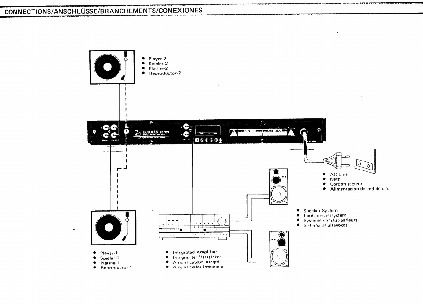
CONNECTIONS/ANSCHLUSSE/BRANCHEMENTS/CONEXIONES
Player-1
Spieler-1
Platine-1
Reproductor-1
Player-2
Spieler-2
Platine-2
Reproductor-2
590088
Integrated
Amplifier
Integrierter
Verstarker
Anplificateur
integré
Amplificador
integrado
a
a
EE
Te
eee
rarer
Tues
eet
ie
iaindeia
Sametadecnh
defeat
ati
Rael
tind
AR
tine
elimi
erintaimaitne
Cordon
secteur
Alimentacion
de
red
de
c.a.
Speaker
System
Lautsprechersystem
Systeme
de
haut-parleurs
Sistema
de
altavoces

DN
a
eet
eel
ieiniatent
aman aeae
oe ae
ET
CONNECTIONS
Player
1
Connect
the
Left
and
Right
output
terminals
of
a
record
plaver
with
an
MC
tyoe
cartridge
to
the
L
and
R
Phono
1
Terminals
(7)
of
this
unit
and
the
Ground
wire
to
the
GND
Terminal
(9)
of
this
unmet
Player
2
Connect
the
Left
and
Right
autput
terminals
of
a
record
player
with
an
MM
aor
MC
type
to
the
bt
and
RB
Phono-2
Terminals
(8)
of
this
unit,
and
the
Ground
wire
to
the
GND
Terminal
(A)
of
this
unit
Connection
to
an
Amplifier
Connect
the
Output
Terminals
(10)
of
this
unit
to
the
Line
In
terminals
of
vour
amplifrer
using
a
high
qrade
pin
piua
cord.
NOTE:
Do
NOT
cnanect
the
Output
Terminals
{10}
of
this
yt
ta
the
Phang
inputs
of
the
amplifier
OPERATION
Turn
ON
the
power
of
this
unit
by
pressing
the
Power
Switch
(1).
The
Phono-1,
or
Phono-2
Indicator
(4)
tights
up,
Sound
is
heard
after
approximately
15
seconds,
This
1s
due
to
the
muting
circuit
being
engaged
when
the
power
1s
turned
on
and
allows
the
power
circuits
inside
the
unit
to
stabilize
before
use
Turn
down
the
volume
of
the
amplifier
until
you
are
ready
to
start
playing
records.
Using
Phono-1
To
select
Phono-1,
press
the
Phono-1
Selector
Switch
:
(A)
When
Phono-1
1s
selected,
the
dedicated
internal
MC
«
amplifier
is
engaged
allowing
the
use
of
almost
any
type
of
MC
cartridge
whatever
its
output
voltage
level
The
Phono-t
pasition
offers
a
straight
signal
path
to
minimize
deterioration
of
the
siqnal.
As
aresult,
the
Subsonic
Filter
(2)
Attenuation
Selector
(3),
input
Sensitivity
(5)
and
Impedance
Selector
(6)
Switches
da
not
funetion
when
Phono-1
ts
selected,
Using
Phono-2
To
select
Phono-2,
press
the
Phono-2
Selector
Switch
(A)
Select
the
sensitivity
by
pressing
one
of
the
Input
Sensitivity
(5)
an
with
the
cartridge
type
used
on
the
player
connected
to
the
Phono-2
Terminals
(8)
When
using
an
MC
type
cartridge,
press
one
of
the
Im.
pedance
Selector
Switches
(6)
to
match
the
cartridge.
Selector
Switches
accordance
Input
Sensitivity
Selector
Switches
MM/0
db
Press
when
using
an
MM.
type
cartridge
??
dB
Press
when
an
MMC
type
cartridge
with
output
valtage
exceeding
0
15
mV
1s
used
3?
dB
Press
when
an
MC
type
cartridge
with
output
voltage
of
less
than
O15
mV
1s
used
Impedance
Selector
Switches
Bohm
Press
when
an
MC
type
cartidge
with
a
load
mmpedance
of
abaut
Go
ohms
16
sed
AD
obi
Prose
when
an
MC
type
cartadae
with
a
toad
mmpedance
of
ahout
40
ohsns
4s
used
TOO
ohm
Press
when
an
MC
tyne
cartadqe
with
a
toad
Impedanern
af
abaat
TO
ohms
ts
ngecf
As
the
impedance
selectton
affects
the
sagad
cuality,
you
may
also
by
trataad
error
press
the
oavitch
that
with
qive
you
the
best
sound
quality
THN
ETERS
EERE
HIE
CEE
TE
WO
SR
I
A
ONE
FE
Ir
een
en
ete
einen
enamel
eee
ae
naiinenateliadtannmennmnsintemememnmaiiiamiants
een
emeadaetenmnainiaaaneenieaseieieunaineenmommnaaeens
Attenuation
Selector
Switches
Used
to
temporarily
reduce
the
volume
level
or
to
match
the
output
level
tothe
input
sensitivity
of
the
amplifier
used.
These
switches
can
also
be
used
for
adapting
the
output
level
when
connecting
the
unit
directly
to
a
power
amplifier
or
simply
when
you
feel
the
sensitivity
of
the
other
equipment
is
tao
high.
Press
the
—
10
dB
switch
to
reduce
the
output
level
by
—10
dB
and
press
the
—20
dB
switch
to
reduce
the
output
level
by
—20
dB.
Subsonic
Filter
Switch
.
Filters
out
the
ultra
low
trequency
components
of
the
signal
which
are
generated
by
warped
records,
tonearm
resonance,
wow
&
flutter
in
the
player
motor,
and
others.
These
frequency
components
May
Cate
harmful
crosstalk,
modulation
or
distortion
and
could
result
in
serious
damage
to
the
woofer
elements
of
your
speakers
NOTE:
lf
the
unit
is
used
in
close
proximity
to
an
integrated
amplifier
or
a
power
amplifier,
induction
hum
may
occur
due
to
magnetic
field
surrounding
the
power
transformer
of
the
amplifier.
In
such
a
case,
put
the
units
further
apart,
and
make
sure
this
unit
is
at
a
safe
distance
from
the
power
transformer
of
the
amplifier
,
Avoid
placing
this
unit
on
top
of
equipment
generating
excessive
heat,
such
as
power
amplifier,
as
thus
will
prevent
heat
dissipation
of
the
other
unit
and
also
could
Thus,
pay
close
attention
to
the
installa-
proper
damage
this
unit
tion
of
the
unit.
AY.
RET
ERT
TI
TEIN
IT
ET
TIS
LO

iad
FE
A
PS
ORT
PE
ARR
8A
OR
aE
A
OTE
SREP
IT
|
AERRNRNET
SRNR
ERR
TNE
ri:
ceietens,
Feat
#
ee
ee
oe
ae
nnn
ne
ne
nn
nanan
mental
aan
aeeaunes
hcthoatite
monet
pins
opens
a.
ANSCHLUSSE
BEDIENUNGSSCHRITTE
iene
te
crmerennennr
as
meme
ene
ee
tae
en
re
en
nt
ne
Rp
tt
Se
RS
TE
Spieler
1
Schalten
Sie
den
Strom
des
Hauptgerats
ein,
indem
Sie
impedanzwahlschalter
SchlieRen
Sie
die
linke
und
die
rechte
Ausgangsbuchse
den
Netzschalter
(1)
drucken.
Die
Anzeigen
fur
entweder
30hm
...
,
.Bei
Anwendung
einer
Cassette
vom
Typ
eines
Plattenspielers
mit
Cassettentyn
MC
an
die
L
und
R
Phonogerat-1
Anschlusse
(PHONO-1)
(7)
dieses
Gerats
und
das
Erdungskabel
an
die
Erdungsbuchse
(GND)
{9)
dieses
Gerates
an
Spieler
2
SchlieRen
Sie
die
linke
und
die
rechte
Ausgangsbuchse
eines
Plattenspielers
mit
Cassettentyo
MM
oder
MC
an
die
L
und
R
Phonogerat-2
Anschliisse
(PHONO-2)
(8)
dieses
Gerats
und
das
Erdungskabel
an
die
Erdungsbuchse
(GND)
(9)
dieses
Gerates
an.
Anschlu8
an
einen
Verstarker
Schtiefen
Sie
die
Ausqangsbuchsen
(10)
dieses
Gerates
an
die
Eingangsleitungsbuchsen
Ihres
Verstarkers
an.
wobei
Sie
einen
Stifstecker
verwenden
HINWEIS:
SchlieRen
Sie
nicht
die
Ausgangsbuchsen
(10)
dieses
Gerates
an
die
Phonngeratbuchsen
des
Verstarkers
an.
Phonogerat-1
oder
2
(PHONO-1
oder
2)
(4)
leuchten
auf.
Ton
ist
nach
ca.
15
Sekunden
horbar.
Eine
Stumm.
schaltung
wirkt
unter
15
Sekunden
und
ermoglicht,
dal&
die
Schaitungen
stabilisiert
werden.
Senken
Sie
die
Lautstarke
des
angeschlossenen
Verstarkers
bevor
Sie
zu
spielen
beginnen.
Anwendung
von
Phonogerat-1
(PHONO-1)
Wahlen
Ste
Phonogerat-1
(FHONO-1)
mit
Hilfe
des
Phonogerat-1
Wahlschalters
(PHONO-1)
(4).
Nach
Wahl
des
Phonogerat-1
(PHONO-1),
stellt
sich
der
ausgewahlte
MC
Verstarker
auf
Betriebsbereitschaft
und
akzeptiert
die
meisten
Typen
von
Cassetten,
unabhangig
von
deren
Ausgangsspan-
nungsniveau.
Die
Phonogerat-1
{PHONO-1)
Position
beinhaltet
einen
geraden
Signalweg,
um
Verzerrungen
des
Signals
zu
mini
mieren.
Daraus
ergibt
sich,
daf&,
wenn
die
Phonogerat-1
(PHONO-1)
Schaltung
eingekoppelt
ist,
der
Unterschallfilter
(2),
der
Dampfungswahlschalter
(3)
der
Eingangswahischal
ter
(5)
und
der
Impedanzwahischalter
(6)
abgeschaltet
werden.
Anwendung
von
Phonogerit-2
(PHONO-2)
Wahten
Sie
Phonogerat-2.
(PHONO-2)
mit
Hilfe
des
Phonogerat-2
Wahischalters
(PHONO.2)
(4).
Bestimmen
Sic
die
Empfindlichkeit
gema&
dem
Cassettentyp
auf
dem
an
die
Lautspecher-2.
Buchse
(PHONO-2)
(8)
angeschlossenen
Plattentellers
mit
Hilfe
des
E:mgangsempfindlichkeitswahl-
schalters
(5).
Wenn
aine
Cassette
vom
Typ
MC
verwendet
wird,
wahlen
Sie
mit
dem
Impedanzwahlschalter
(6)
eine
Impedanz,
die
der
Cassette
entspricht.
Eingangsempfindlichkeitswahlischalter
MM/O
dB...
Bei
Anwendung
einer
Cassette
vom
Typ
MM.
22.dB...~0~.«.
Bei
Anwendung
einer
Cassette
vam
Typ
MC
mit
Ausgangsspannung
Uber
0,15mV
32
dB
Bei
Anwendung
einer
Cassette
vom
Typ
MC
mit
Ausgangsspannung
unter
0,15
mv.
MC
mit
einer
lLadungsimpedanz
von
ungefahr
3
Ohm.
Bei
Anwendung
einer
Cassette
vom
Typ
MC
mit
einer
Ladungsimpedanz
von
ungefahr
40
Ohm.
10O0Ohm.......
Bei
Anwendung
ener
Cassette
vom
Typ
MC
mit
einer
Ladungsimpedanz
von
ungefahr
100
Ohm.
;
Da
die
Impedanzwahl
die
Tonqualitat
beeinflu&t,
konnen
Sie
durch
Versuchen
den
Schalter
so
einstellen,
da®
Sie
die
beste
Tonqualitat
erhalten.
40
Ohm
Dampfungswah!schaiter
Werden
angewendet,
um
die
Lautstarke
zufallig
oder
gemaR
der
Eingangsempfindlichkeit
des
angeschlossenen
Verstarkers
zu
reduzieren.
Werden
ebenfalls
verwendet.
wenn
cas
Gerat
direkt
an
die
Einganasbuchsen
des
Verstarkers
angeschlossen
ist
oder
die
Empfindlichkeit)
zu
hoch
ist.
Durch
Driicken
auf
den
—10
dB-Schalter
wird
die
Lautstarke
um
10
dB,
durch
Drucken
auf
den
—20
dB-Schalter
um
20
dB
gesenkt.
Unterschalifilterschalter
Unterdruckt
ultra
niedrige
Frequenztone,
die
durch
verzogene
Aufnahmen,
Tonarmresonanz
oder
Gleichlauf-
schwankungen
des
Plattentellers
entstehen
konnen
und
storendes
Nebensprechen,
Veranderungen
und
Verzerrungen
verursachen
kannen
und
als
sotche
Schaden
an
Tetlen
Ihrer
Tieftonlautsprecher
verursachen
kunnten.
HINWEIS:
Wenn
das
Gerat
in
der
Nahe
eines
intearierten
Verstarkers
oder
eines
Kraftverstarkers
verwendet
wird,
kann
durch
Magnetstromuberflu8
vom
Stromtransformator
oder
Ver.
starker
ein
Brummen
durch
Induktion
entstehen.
Im
diesem
Fall
sotlten
Sie
versuchen,
die
Gerate
voneinander
getrennt
zu
halten
und
halten
Sie
das
Gerat
in
sicherer
Entfernung
vom
Stromtransformator
und
dem
Verstarker.
Sollte
das
Gerat
auf
einem
Gegenstand,
der
starke
Warme
entwickelt,
z.8.
Stromverstarker,
gestellt
werden,
kann
das
Gerat
die
Ableitung
der
Warme
vom
anderen
Gerat
behindern
und
das
Gerat
selbst
kann
beschaddigt
werden.
Beachten
Sie
deshalb
sorgfaltig
die
Installation
des
Gerats

Ts
ademhlaeee
tet
hiatiaaenta
tn:
nent
ine
beeen
th
ett
acid ilin
ba
amenmetnathinee
me
esicbn
eae
Sats
peenwermanges
1
A
emmremmenarapryme
sre
as
ee
core
a
eT
ST
ate
li
acta
Staaten
cence
Renata
nadine
SPECIFICATIONS
_
TECHNISCHE
DATEN
FICHE
TECHNIQUE
pep
reece
meer
Le
ene
eee
pe
ee
Ae
AY
IETS
EE
Re:
eee
cee
et
of
oot
oe
mint
en
era
ene
eteeenh
attest
eg
1
RT
ee
IAT
PERRO
Se
Te
IATA
ETON
DT
TET
EE
SORTS
OE
Rated
Cutout
Power»...
7.
ee
150
mV
Nenn-Ausgangsspannundg,
.
2.
.
Soe
ee
.
150mv
Sortie
nominale
oo
ee
a
—,
.
150mVv
Output
impedance
(Phono-1)
0...
_
70
ohms
Ausgangsimpedanz
(Phono
1).
0.0...
......
7OOhm
Impédance
de
sortie
{Phono
1).
ee
70
ohms
Total
Harmonic
Distortion
(1
kKH2).
0 0
2,
.
0.005%
Gesamtklirrfaktor
(1
kKH7).
00
..00002...0.0.
0,005%
Distorsion
harmonique
totale
(1
kHz)...
0.2...
.
0.005%
Input
Sensitivity.
Einganasempfindlichkeit
Sensibilité
dentrée:
PRaWO
Tn
Gh!
So
tag
RAS
160pV
Phonogerat
1
(Phono
1)...
0.
.
Jo...
160LV
Phonod
oo.
Beh
seo
160uUV
Phonan
2,0dB
Reheat
Sh,
BSR
Est
3
ee
25
mV
Phonogerat
2
(Phono
2),0dB............
2,5mV
Phono
2,0dB....02020.....
0-2-2005
55
2,5mV
Phono
2,
22
«1B
geet
ke
a
Dee
ee.
220
Phonogerat
2
(Phono
2),22dB...........
220UV
Phono
2:27'dB
.
od
ace
oe
be
bo
es
220UV
Phono
2,32d8...
..............
2.
BOLV
Phonogerat
2
(Phono
2),32dB...........
.
BOUV
Phono
2,32dB.
2.2...
tiene
Boosh
ee
BOUV
Input
tmnedance
Eingangsimpedanz
:
Impédance
d’entrée.
Phono
1
be,
MR
Sepik
ode
ee
Bradt
eS
100
ahm
Phonogerat
1
(Phono
1).
000.
2...
100
OHM
PHonoel!:
2
ft
ya
ses,
BAS
oo...
.
100
0hms
Phono ?,.MM
7.
odd
a
Ak
ohm
Phonogerat
2
(Phono
2),
MM
oo,
~...
.
47k
Ohm
Phono
?,MM
..
1...
ooo...
47k
ohms
Phono
2,
MC
:
—.
,
31407100
ohms
Phonogerat
2
(Phono
2),MC
.
~.
.
3/40/100
Ohm
Phono
2,MC.
ee
3/40/100
ahms
S/N
ratio
(A
weighted,
rapt:
shorted
1V
output):
Rauschabstand
(nach
A,
1V
Eingang
Gberbrick
t)
Rapport
signal/bruit
(A
pondérde,
1V,
entrée
en
court-circuit):
MC
Straight
;
ecnnh
Mibc
Meehan,
AA
aie
oth
dese
77
dB
MC
Geradeaus.
0
00...
Re
in”
acne
ht
_
77
dB
MC
direct
2.0.0...
abe
enn
il
ete
td
ae
77
0B
IMM
apt.
ted
fod
a
kek
Be
Gad,
aver
tobe
2S
.
.
92
dB
MMi
eens
bs
Ab
ad
ken
FOND
Strid,
ated
NAM
feces
ohana
<e
2,
Re
Re
ks
oo...
.
92
dB
Frequency
Response.
Wiedergabefrequenz:
Réponse
en
fréquence:
Phono
(MM/MC})
20
ow.
20
Hz
—
30
H2
(~1.0
dB)
Phongerat
(MM/MC)
00...
20
Hz
—
30
Hz
(~1.0
dB)
Phono
(MM/MC)
...
..
_,
20Hz—
30
Hz
(-1.0
dB)
30
Hz
—
20,000
Hz
(40
5
dB)
30
H7
—
20.000
Hz
(+05
dB)
30
Hz
-.
20.000
Hz
(+0.5
dB}
Crosstalk
(Phang
1)
Ady
tet
85
dB
Nebensprechen
(Phono
1)
a
28
85
dB
Couplage
parasite
(Phono
1).
..
84dB
Filter
Subsonic
apie
won
eoch
Baer
fee
18
Hz,
~3
dB/oct.
Unterschallfiterschalter
2
0...
2...
18
He,
-3
dB/Okt.
Filtre
subsonique
2.0
0...
.
18
Hz,
-3.dB/oct.
Power
Supply
.
Ree
ete
©
hte
eee,
seteos
120/200/240V
Netzanschlu@®
...
2
..............
120/200/240V
Alimentation
secteur.
2
0.)
420/200/240V
Power
Consumption
0
ow
25W
Leistungsaufmahme
2.
ee
_
25
Watt
Consommation
de
puissance.
Ronis
Jet
ees
ee
ah
aetna
cte
2
25W
Dimensions
=.
7
2...
_
438
(W})
x
63
(H}
x
310{(D)
mm
AuBenabmessungen.
.
0...
"438
(B)
x
63
(H)
x
310
(T)
mm
Dimensions
...........
438(L)
x
63(H)
x
310(P)
mm
Weight
2
Dia
Se
2
Oe
Sumen
Faas
AS
kg
GeViCWE:
&
etd
ee
i
FE
BBs
Obl
2
eel
A5kq
POIGSs,
2
o0e
on
Bonet
ele
dl
at
ahd
da
fg
RA
eh
Ae:
45kqg
Specifications
and
appearance
design
are
subject
to
change
Anderungen
auf
Grund
der
Verbesserung
der
Technik
und
Les
caractéristiques
et
te
dessin
pourront
subir
des
modifica.
without
notice
des
Designs
behalten
wir
uns
ohne
vorheriqe
Ankundiqung
tions
sans
préavis.
vor.
nn
ee
eanamatenetiaetinenemnenemetmeentnmmemenmetenmmnssmnncumememanminenmecnatennenemmneniaeat
ins
ESPECIFICACIONES
Meee
ee
cement
mnceemccompeamreatem
cama:
sbuteacienn
che
iemncnanemia
hatte
ast
diiaeitettictitatate
ieiaimaaniabeaaiaiiets,
wamietaiitah
snaaiinaatiaealisieasianinaaamen
naan
Salida
nominal...
0.02...
150mVv
Respuesta
en
frecuencia,
Consuma
de
potencia,
2
25W
Impedancia
de
salida
(Phono
1)...
—..
Wohmins
Phono
(MM/MC)
2.
2OHe
~
30
Hz
(-1.0
dB)
Dimensiones.
2...
438
anc
ho)
x
63{atto)
x
310(prof.)
mm
~
Distorsidn
armaénica
total
(7
kHz)
0
0.
~
0,005%
30
tty
|
20.000
112
(40,5
dB)
PSs
OS.
i
fs
Sol
cet
Se
Sts
eed
ME
rv
NES
Pee
hee ase
ae
45kg
Sensibilidad
de
entrada
°
(uafonta
(Phono
1).
85
dB
Phonol
, :
Pare
1860p
Filtro
subsdnico.
9.
he
18H,
--3dB/oct,
Las
especificaciones
y
el
aspecta
pureden
modificarse
sin
#
Phono
2,
048.
weyittle
«
Sotl_apadees
aoe
i,
An
2
Sim
Atimmantacion
sector
oo
0
0
120/200/240V
previo
aviso
;
Phono
2,
22
dB
;
oe
PAO
E
Phono
2,324B
0.202...
Ge
ede
QA
_,
BOpY
Impedancia
de
entrada
PRann
1
.
TOO
ohmins
ee
ie
i
LUX
CORPORATION,
JAPAN
Phono
2,
8.10
:
BANA
IDO
ohenios
4
E
Relacian
seal
a
niido
(A
pon
derada,
2-3,
1-Chome,
Minami-Yuk
igaya,
Ohta-ku,
Tokyo
145,
JAPAN
‘
1V
entrada
cortociremitada)
Phone:
03-726-6211
Telex
2466953LUXMAN
Facsimile’
03-728-7609
MC
\
inpal
/;
ane
MIM
alfa
68P81707F
22.0
Printed
in
Japan
tmornimeé
an
Japon
Fe
Table of contents