Figure 2-3 3-axis Adjustment
0 ~360° °
0 ~75° °
0 ~360° °
2.2 Installa n of Type CameraII
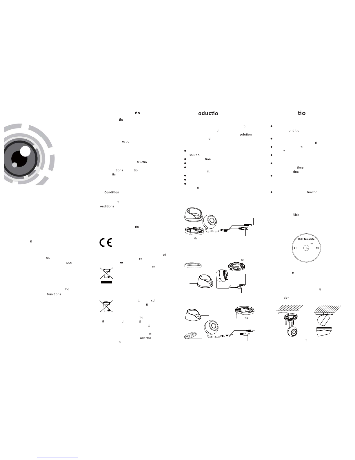
Steps:
Figure 2-4 The Drill Template
Figure 2-5 Fix the camera to the ceiling
Figure 2-6
2.3 Installa n of Type CameraIII
Steps:
3 Menu Opera n
Figure 3-1 Main Menu
Menu
SCENE LENS RESET
EXPOSURE WB DAY&NIGHT
BACKL IGHT NR SPECIAL ADJUST
INDOO R
OUTDO OR
INDOOR 1
LOW-
LIGHT
MANUAL SHUTT ER
AGC
SENS-U P
BRIGHTNESS
D-WDR
DEFOG
BLC
HSBLC
ATW
AWC-SET
INDOO R
OUTDO OR
MANUAL
COLOR
B/W
EXT
2D NR
3D NR
CAM
TITLE
D-EFFEC T
MOTIO N
PRIVAC Y
LAUGUAGE
DEFECT
VERSIO N
SHARPN ESS
MONIT OR
LSC
VIDEO.
OUT
EXIT
SETUP
A coaxial camera controller (purchase separately)
is required to select the menu and adjust the
camera parameters.
3.1 VIDEO.OUT
PAL or NTSC is selectable .
3.2 LANGUAGE
English, Japanese, CHN1, CHN2, Korean, German,
French, Italian, Spanish, Polish, etc., are selectable.
3.3SETUP
3.3.1 SCENE
You can select indoor, outdoor, indoor 1 and low
-light as the working environments.
3.3.2 LENS
The camera is equipped with a fixed lens.
3.3.3 EXPOSURE
EXPOSURE
1. SHUTTER AUTO
2. AGC OFF
3. SENS-UP ---
4. BRIGHTNESS ---|------ 40
5. DEFOG OFF
6. BACKLIGHT OFF
7. RETURN RET
Figure 3-2 Exposure
SHUTTER: AUTO,1/25, 1/50, FLK, 1/200, 1/400,
1/1k, 1/2k, 1/5k, 1/10k, 1/50k, x2, x4, x6, x8, x10,
and x15 are selectable.
: You can set the AGC value from 0 to 15.AGC
: You can set the SENS-UP to OFF or AUTO.SENS-UP
: You can set the brightness valueBRIGHTNESS
from 1 to 100.
: You can set the D-WDR to ON to improveD-WDR
the image quality or OFF to disable the func on.
: You can set the defog func on as ON toDEFOG
enable the . P , size, and the defog
grada n are configurable.
3.3.4 Backlight
Backlight Compensan (BLC):
Set the gain of BLC as High, Middle, or Low.-GAIN:
Press the up/down/le ht bu on to-AREA:
define the BLC n and size. Select RET or
AGAIN to go back the BLC menu or re-define the
BLC area.
Restore the BLC se ngs to the default.-Default:
HSBLC:
Select an HSBLC area. Set the DISPLAY status as ON.
Press the up/down/le ht bu on to define the
area posi on and size. Set the HSBLC LEVEL from 0
to 100. Select ALL DAY or Night for the HSBLC mode.
Set the BLACK MASK status as ON or OFF.
HSBLC
1. SELECT AREA 1
2. DISPLAY ON
3. LEVEL ---|------ 40
4. MODE ALL DAY
5. BLACK MASK ON
6. DEFAULT
7. RETURN RET
Figure 3-3 HSBLC
3.3.5 White Balance (WB)
INDOOR, OUTDOOR, MANUAL, ATW (Auto-tracking
White Balance), AWC→SET are selectable.
3.3.6 Day & Night
Color, B/W, and EXT are selectable for DAY and
NIGHT switches.
3.3.7 NR
: You can set 2D NR status as ON or OFF.2D NR
: Set the Smart NR status as ON and adjust3D NR
the 3D smart NR sensi ty ranges from 0 to 100.
Set the 3D NR LEVEL ranges from 0 to 100. Set the
2D&3D NR
1. 2DNR OFF
2. 3DNR ON
3. RETURN RET
3D NR
1. SMART NR ON
2. LEVEL ------|--8 0
3. START. AGC -|--------10
4. END. AGC -|--------10
5. RETURN RET
Figure 3-5 NR
Figure 3-6 3D NR
3.3.8 SPECIAL
: Edit the camera tle on this sec on.Camera Title
:D-effect
: Set the freeze func on as ON or OFF.-FREEZE
: OFF, MIRROR, V-FLIP, and ROTATE are-MIRROR
selectable for mirror.
: Define the zoom area by configuring-D-ZOOM
the posi on from PAN & TILT.
: The D-Zoom area, y-SMART D-ZOOM
and e are configurable.
: Set the NEG IMAGE as ON or OFF.-NEG.IMAGE
SPECIAL
1. CAM TITLE ON
2. D-DFFECT
3. MOTION OFF
4. PRIVACY OFF
5. LANGUAGE ENG
6. DEFECT
7. VERSION 130722
8. RETURN RET
Figure 3-7 Special
MOTION
1. SELECT AREA 1
2. DISPLAY ON
3. SENSITIVITY ----|---- 30
4. MOTION VIEW ON
5. DEFAULT
6. RETURN RET
Figure 3-8 Mo on Detec on
Mon: Select a MOTION area. Set the DISPLAY
status as ON or OFF. Press the up/down/le right
bu on to define the posi on and size of the area.
Set the SENSITIVITY from 0 to 60. Set the MOTION
VIEW status as ON or OFF.
Privacy: Select a PRIVACY area. Set the DISPLAY
status as INV, MOSAIC, COLOR or OFF. Press the
up/down/le ht bu on to define the n
and size of the area.
Defect: LIVE DPC, STATIC DPC and Black DPC are
adjustable in this .
: You can check the s ware version of theVersion
device.
PRIVACY
1. SELECT AREA 1
2. DISPLAY MOSAIC
3. COLOR 10
4. TRANS. 1
5. DEFAULT
6. RETURN RET
ADJUST
1. SHARPNESS --------|15
2. MONITOR LCD
3. LSC OFF
4. VIDEO. OUT PAL
5. RETURN RET
3.3.9 ADJUST
: Adjust the sharpness from 0 to 15.Sharpness
: Monitor CRT, and Monitor LCD areMonitor
selectable.
: Set the LSC status as ON or OFF.LSC
3.3.10 RESET
Reset all the se ngs to the default.
3.3.11 EXIT
Press OK to exit the menu.
START. AGC level as the threshold to enable AGC,
and set the END. AGC level as the threshold to
disable AGC.
Figure 3-9 Privacy Mask Figure 3-10 Adjust
Hole 1: for moun ng base
Hole A: for cables routed
through the wall.
Cameras with a 720p resolu on of these three
types do not support menu opera .
1.Drill the screw holes and the cable hole on the
ceiling according to the supplied drill template.
Figure 2-6 The Drill Template
2.Fix the moun g base to the ceiling with the
supplied screws.
Hole 1: for moun ng base
Hole A: for cables routed
through the wall.
Figure 2-7 Fix the Moun ng Base and Camera
3.Route the cables to the cable hole and connect
corresponding power cable and video cable.
4.Secure the camera to the moun ng base.
5.Fix the enclosure to camera.
6.Adjust the camera according to the figure
below to get an op mum angle.
Figure 2-8 3-axis Adjustment
6.Adjust the camera according to the figure below
to get an op mum angle.
1.Drill the screw holes and the cable hole on the
ceiling according to the drill template.
2.Connect the corresponding power/video cables.
3.Insert the supplied screws to the screw holes
the ceiling.
4.Loosen the lock screw.
5.Rotate the enclosure to adjust the pan angle;
6.Tighten the lock screw to clamp the lens.
o
7.
8.Rotate the trim ring clockwise to secure it to
the camera.
Install the trim ring