Bulletin281-167 Page 2
PLEASE READ THESE INSTRUCTIONS
CAREFULLY.
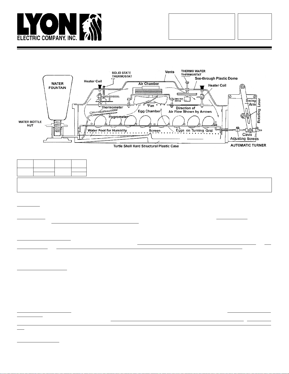
Position the Roll-X in front of you so that the water fountain is to the
back and on your left side. This will aid you in adjusting the Roll-X.
Materials needed to assemble the Roll-X:
Small flat head screwdriver
Crescent wrench
UNPACKING T
HE RX-2
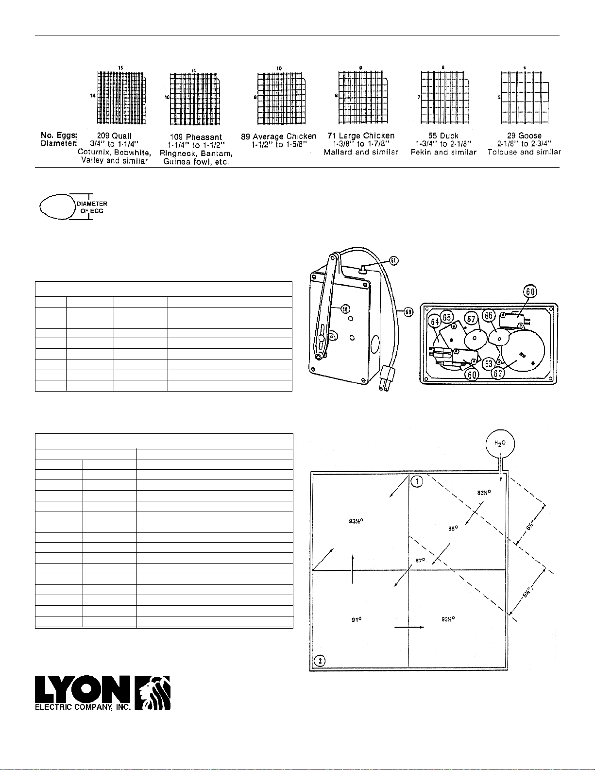
1. Carefully remove and identify the following as you unpack the
Roll-X.
Clear plastic dome ( packed upside down)
Grid assembly (for packaging purposes the grid assembly is
shipped upside down)
Screen mesh
Blue Plastic base
Water fountain kit
The thermometer/hygrometer kit in plastic bag which includes:
One flat washer
One wing washer/nut
One long bolt
(3) hex nuts
One mercury thermometer with a wick attached to the
end of the thermometer (wet bulb),
One regular thermometer (dry bulb),
The L-shaped turning pull rod with black screw on cap
2. IFTHE UNIT IS AUTOMATIC,THEFOLLOWING ITEMS
AREENCLOSED:
Automatic turner (available in 110VAC and 220VAC)
Two (2) screws and two (2) washers
L-shaped turning pull-rod with two (2) adjusting screws and collars.
3. Assembling the Roll-X2: (see ADJUSTING AUTOMATIC TURNER).
SKIP THIS INSTRUCTION IF YOUR ROLL-X IS MANUALLY OPERATED.
Remove the grid assembly and screen mesh from the inside of the blue
base. Take the automatic turner and match the two holes in the blue base
to the two threaded inserts on the side of the turner. Put the two screws
with the washers on them through the wall from the inside of the incubator
base. Place the turner against the base and tighten the screws. Do not
overtighten the screws. From the inside of the blue base insert the L-
shaped turning rod through the hole of the blue base wall. The short end
should remain on the inside of the base. Place one set collar and adjusting
screw on the L-shaped pull-rod located on the outside of the incubator.
Run the rod through the clevis hole on the bottom of the swing arm of the
turner and attach the second set collar and adjusting screw to the pull-rod.
Do not tighten the adjusting screws onto the pull-rod at this time. Final
adjustments will be made later.
4. SKIP THIS INSTRUCTION IF YOUR ROLL-X IS AUTOMATICALLY
TURNED. Insert the L-shaped turning pull-rod from the inside of the blue
base with the short end remaining on the inside of the base.
5. Place the mesh screen directly on the bottom supports of the blue
base, with the notched out corner where hole for water bottle is located
(And the thermometer kit attaches). Place the grid assembly (plastic coated
side down, bright plated side up) over the screen. Be sure the guide rollers
are connected between the plastic coated and bright plated grids. The
grid assemblies should be resting against each other firmly but move freely
without friction against the walls of the blue base.
NOTE: If the grid assembly appears to "climb the walls” it is upside down.
Connect the turner pull rod Inside the base with the small plastic loop on
the end of the removable grid. (Make sure the notched corner of the grid
assembly
is on the opposite side of the blue base from the turner.)
INSTALLING YOUR THERMOMETER KIT
6. Locate the hole on the back side of the base next to the water
fountain. From the inside of the base, insert the thermometer assembly
and apply the washer and wing nut to the exterior of the blue base.
Tighten the wing nut snugly, but do not over tighten. (The
thermometer assembly should extend to the right with the wick
hanging down to the front right corner).
The bulbs of the thermometers should slant downward but still clear
the eggs to be set. Extend the wick of the wet-bulb or hygrometer
through the grid notch so that the end will rest on the bottom of the
base.
INSTALLING EXTERNAL WATER FOUNTAIN
7. To install the external water fountain:
A. Insertthe threadedhose barbfitting intothe threaded hole provided
in the bottom blue base corner where the Thermometer/
Hygrometer kit is mounted. Tighten enough to prevent leaking.
B. Push the hose piece provided onto the white hose barb that is
screwed into blue base.
C. Push the hose barb on the water fountain base into the hose.
D. When ready the water fountain bottle height (and thus the water
height in the incubator) is adjusted by raising or lowering the nut on
the neck of the water fountain bottle.
8. NOW PLACE ROLL-X DOME ON BLUE BASE
Plug the long cord from the dome into your electric power source. If
you have an Automatic Turner, plug the Automatic Turner cord into
the electrical receptacle on the dome (Remember: it is only for the
automatic turner).
ADJUSTINGTHEAUTOMATICTURNER
Skip instruction if your RX is manually turned.
CAUTION: Do not tighten the adjusting screws on the L-shaped turning pull
rod until they are in the proper position. The incorrect positioning may cause
the turning grid to be forced against the walls of the incubator and break
either the automatic turner or the connections to it.
Lift the Dome and move the grid to the left (away from the automatic turner)
to within 1/4" of the incubator wall. Press the red button on the top of the
automatic turner. This will activate the automatic turner and cause the lever
to move either to the right or left. Observe the lever as it moves to the left.
At this point when the lever reaches the maximum position to the left re-
move your finger from the red button and tighten the adjusting screw against
the clevis at the left and tighten the adjusting screw against the clevis at the
right.
SETTING TEMPERATURE CONTROLS
Theincubatorwastestedandthe temperature regulatedto100°Fbeforeitwas
shippedtoyou. Due tohandling in shipmentor the environment itis used in,it
mayrequirefurtheradjustment. Temperatureadjustmentis made according to
thetypeofcontrolorderedwith the incubator. Theyaredescribedinthe follow-
ing paragraphs. Watch the thermometer as the temperature in the incubator
rises. The indicator light should go off at 100°F. After the set temperature is
reached the light will go on and off at short intervals. This on and off of the
indicatorlightand a constantthermometerreading of 100°Findicatesthether-
mostatiscontrollingtheheat.